Steca StecaGrid 3000 Installations- Und Bedienungsanleitung
Vorschau ausblenden
Andere Handbücher für StecaGrid 3000:
- Bedienungs und installationsanleitung handbuch (132 Seiten) ,
- Kurzinstallationsanleitung (2 Seiten)

Verwandte Anleitungen für Steca StecaGrid 3000


Inhaltszusammenfassung für Steca StecaGrid 3000
- Seite 1 StecaGrid 3000 StecaGrid 3600 StecaGrid 4200 Installations- und Bedienungsanleitung Installation and operating instructions Notice d'installation et d'utilisation DE EN FR 746.217 | 12.27 | Z05.1...
- Seite 2 Inhalt – Contents – Table des matières Deutsch English Français Appendix Montage – Installation – Montage Zertifikate – Certificates – Certificats 746.217 | 12.27 | Z05.1...
-
Seite 3: Inhaltsverzeichnis
Inhalt Vorwort Identifizierung Allgemeine Sicherheitshinweise Lieferumfang Bestimmungsgemäße Verwendung Zu dieser Anleitung Inhalt Zielgruppe Kennzeichnungen Aufbau und Funktion Gehäuse Bedientasten Display Kühlung Netzüberwachung Datenkommunikation Installation Sicherheitsmaßnahmen bei der Installation Wechselrichter montieren AC-Anschluss vorbereiten DC-Anschlüsse vorbereiten Datenverbindungskabel vorbereiten Wechselrichter anschließen und AC einschalten Erste Inbetriebnahme des Wechselrichters DC einschalten Wechselrichter demontieren... -
Seite 4: Vorwort
Höchste Effizienz mit langer Lebensdauer Die innovative Wechselrichter-Topologie Coolcept, die auf einem einstufigen, trafolosen Schaltkon- zept basiert, wird im StecaGrid 3000, 3600 und 4200 integriert und erreicht Spitzenwirkungsgrade von 98,6 %. Auch der europäische Wirkungsgrad der Geräte liegt deutlich über 98 % und setzt damit Maßstäbe im Bereich der Photovoltaik-Netzeinspeisung. -
Seite 5: Identifizierung
Identifizierung Allgemein Merkmal Beschreibung StecaGrid 3000 / StecaGrid 3600 / StecaGrid 4200 Ausgabestand der Anleitung Herstelleradresse Siehe Kontakt, S. 44. Zertifikate Siehe S. 137 und www.stecasolar.com StecaGrid 3000 / 3600 / 4200 Optionales Zubehör • Fernanzeige StecaGrid Vision • externer Datenlogger: WEB‘log der Firma Meteocontrol... -
Seite 6: Allgemeine Sicherheitshinweise
Allgemeine Sicherheitshinweise • Dieses Dokument ist Teil des Produkts. • Installieren und benutzen Sie das Gerät erst, nachdem Sie dieses Dokument gelesen und verstan- den haben. • Führen Sie die in diesem Dokument beschriebenen Maßnahmen immer in der angegebenen Rei- henfolge durch. -
Seite 7: Lieferumfang
Lieferumfang • StecaGrid 3000/3600/4200 • Montageplatte • AC-Stecker • Installations- und Bedienungsanleitung StecaGrid 3000 StecaGrid 3600 StecaGrid 4200 Installations- und Bedienungsanleitung Installation and operating instructions Notice d'installation et d'utilisation DE EN FR 746.217 | 12.27 | Z01... -
Seite 8: Zu Dieser Anleitung
Zu dieser Anleitung Inhalt Diese Anleitung enthält alle Informationen, die eine Fachkraft zum Einrichten und Betreiben des Wechselrichters benötigt. Beachten Sie bei der Montage weiterer Komponenten (z. B. Solarmodule, Verkabelung) die Anleitungen der jeweiligen Hersteller. Zielgruppe Zielgruppe dieser Anleitung sind Fachkräfte und Anlagenbetreiber, soweit nicht anders gekennzeichnet. Mit Fachkräften sind hier Personen bezeichnet, welche unter anderem • über die Kenntnis einschlägiger Begriffe und Fertigkeiten beim Einrichten und Betreiben von Photovoltaik-Systemen verfügen. -
Seite 9: Abkürzungen
6.3.4 Abkürzungen Abkürzung Beschreibung Derating Leistungsreduzierung interne Netzüberwachung des Wechselrichters (deutsch: Einrichtung zur Netz- überwachung mit zugeordneten Schaltorganen). Arbeitspunkt mit der höchsten Leistungsabgabe (engl.: maximum power point) SELV, TBTS, MBTS Schutzkleinspannung (EN: Safety Extra Low Voltage; FR: Très Basse Tension de Sécurité;... -
Seite 10: Aufbau Und Funktion
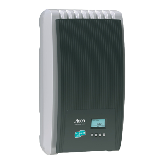
Aufbau und Funktion Gehäuse Haube Display (monochrom, 128 x 64 Pixel) Typenschild, Warnhinweise Bedientasten: ESC, , , SET (von links nach rechts) 1x AC-Anschluss 2x RJ45-Buchsen (RS485-Schnittstelle) 1x DC-Anschluss Minus (−) für Solarmodule (Multi-Con- tact DC Buchse MC4, berührungssicher) 1x DC-Anschluss Plus (+) für Solarmodule (Multi-Con- tact DC Buchse MC4, berührungssicher) DC-Lasttrennschalter (trennt Plus- und Minuseingang gleichzeitig) -
Seite 11: Bedientasten
Bedientasten Die Bedientasten ( in Abb. 5) haben folgende Funktionen: Funktion Taste Aktion allgemein geführte Bedienung ESC kurz drücken springt eine Menüebene höher geht 1 Schritt zurück verwirft eine Änderung lange drücken springt zur Statusanzeige springt zum Anfang der geführten (≥ 1 Sekunde) Bedienung kurz drücken... - Seite 12 7.3.2 Informationen Die am Display angezeigten Informationen sind nachstehend anhand von Abbildungsbeispielen beschrieben. Statusanzeige In der Statusanzeige werden Messwerte wie folgt einzeln angezeigt: Messwertname Messwert mit Einheit Datum Symbol nicht quittierte Ereignismeldungen; mehr dazu im Abschnitt 11, S. 35. ...
-
Seite 13: Ertrag Grafisch (Tage, Monate, Jahre)
Ertrag grafisch (Tage, Monate, Jahre) Tages-, Monats- und Jahreserträge können grafisch in einem Diagramm angezeigt werden. Zeitraum eines Einzelertrags (hier: Tagesertrag) y-Achse: Ertrag in kWh – Mit Zusatz M: Ertrag in MWh – Skalierung ändert sich je nach Maximalwert –... -
Seite 14: Steuerelemente
7.3.3 Steuerelemente Die am Display angezeigten Steuerelemente zum Einstellen des Wechselrichters sind nachstehend anhand von Abbildungsbeispielen beschrieben. Auswahlliste mit Kontrollkästchen Bezeichnung der Auswahlliste Kontrollkästchen mit Namen: Kontrollkästchen ermöglichen Mehrfachauswahl – das markierte Kontrollkästchen ist schwarz unterlegt – voreingestellte Kontrollkästchen haben keinen Rahmen –... -
Seite 15: Auswahl Messwerte
7.3.4 Weitere wichtige Display-Inhalte Dialog Maximalwerte rücksetzen Mit dem Dialog Maximalwerte rücksetzen können die fol- genden gespeicherten Maximalwerte auf 0 zurückgesetzt werden: • Tagesmaximalleistung • Tagesmaximalertrag • Absolute Maximalleistung Auswahl Messwerte Auswahl der Messwerte, die in der Statusanzeige angezeigt werden können. Folgende Messwerte können ausgewählt werden: • Ausgangsleistung: Ausgangsleistung des Wechselrich- ters... -
Seite 16: Hintergrundbeleuchtung
Hintergrundbeleuchtung • aus • automatisch: nach Tastendruck 30 Sekunden einge- schaltet • Einspeisebetrieb: kein Einspeisen: nach Tastendruck 30 Sekunden einge- – schaltet, danach ausgeschaltet Einspeisen: nach Tastendruck 30 Sekunden eingeschal- – tet, danach gedimmt 7.3.5 Service-Menü Nachfolgend sind die Einträge des Service-Menüs beschrieben. Einige Einträge sind passwortge- schützt;... -
Seite 17: Werkseinstellung
Werkseinstellung Beim Rücksetzen auf die Werkseinstellung werden folgende Daten gelöscht: • Ertragsdaten • Ereignismeldungen • Datum und Uhrzeit • Ländereinstellung • Display-Sprache Nachdem die Werkseinstellung gelöscht wurde, startet das Gerät neu und zeigt die geführte erste Inbetriebnahme an. Spannungsgrenzen (Spitzenwert) Folgende Spannungsgrenzen können geändert werden: • oberer Abschaltwert Spannung • unterer Abschaltwert Spannung... - Seite 18 Technische Einzelheiten • Jede Kennlinie ist definiert durch 2 bis 8 Stützstellen. • Eine Stützstelle ist definiert durch die Ausgangsleistung P des Wechselrichters (x-Achse) und die zugehörige Phasen- verschiebung (y-Achse). • Die Phasenverschiebung kann eingestellt werden im Bereich von 0,95 (Übererregung) über 1,00 (keine Phasen- verschiebung) bis 0,95 (Untererregung).
-
Seite 19: Kühlung
Kühlung Die interne Temperaturregelung verhindert überhöhte Betriebstemperaturen. Wenn seine Innentem- peratur zu hoch ist, passt der Wechselrichter die Leistungsaufnahme aus den Solarmodulen automa- tisch an, sodass Wärmeabgabe und Betriebstemperatur sinken. Der Wechselrichter wird mit Kühlrippen an Vorder- und Rückseite durch Konvektion gekühlt. Inner- halb des abgeschlossenen Gehäuses verteilt ein wartungsfreier Ventilator die Abwärme gleichmäßig auf die Gehäuseoberfläche. - Seite 20 – Wechselrichter-Informationen mittels Steca Service-Software auslesen – Anschluss an den Wechselrichter über optionalen Adapter RS485/USB möglich. Der Adapter ist bei Steca erhältlich. • externe Datenlogger, von Steca für eine professionelle Systemüberwachung empfohlen: – StecaGrid Monitor – WEB‘log (Fa. Meteocontrol) – Solar-Log (Fa. Solare Datensysteme) Hinweis An den externen Datenloggern müssen vor dem Anschließen die Einstellungen gemäß...
-
Seite 21: Terminierung
externe Datenlogger Gerät Wechselrichter StecaGrid Vision StecaGrid Monitor Solar-Log WEB‘log Signal Stecker RJ45 RJ45 COMBICON Klemmleiste Klemmleiste RJ12 19 / 11 / 15 Data A 21 / 13 / 17 Data B – – – – – – – –... -
Seite 22: Installation
Installation Sicherheitsmaßnahmen bei der Installation Beachten Sie bei den im Abschnitt Installation beschriebenen Maßnahmen die folgenden Sicher- heitshinweise. Gefahr Lebensgefahr durch Stromschlag! • Nur Fachkräfte dürfen die im Abschnitt Installation beschriebenen Maßnahmen durchführen. • Vor Arbeiten am Wechselrichter immer alle DC- und AC-Leitungen wie folgt trennen: 1. -
Seite 23: Wechselrichter Montieren
Wechselrichter montieren Montageplatte befestigen Montageplatte mit 4 Schrauben an der Montagefläche befes- tigen: Dem Gewicht des Wechselrichters entsprechende Schrau- – ben (und Dübel etc.) verwenden. Die Montageplatte muss eben an der Montagefläche anlie- – gen, die seitlichen Blechstreifen müssen nach vorne weisen (Abb. -
Seite 24: Ac-Anschluss Vorbereiten
AC-Anschluss vorbereiten 8.3.1 Leitungsschutzschalter Informationen zum erforderlichen Leitungsschutzschalter und zu den Kabeln zwischen Wechselrich- ter und Leitungsschutzschalter finden Sie im Abschnitt 14.2, S. 41. 8.3.2 Fehlerstromschutzschalter Wenn die örtlichen Installationsvorschriften die Installation eines externen Fehlerstromschutzschal- ters vorschreiben, dann ist gemäß IEC 62109-1, § 7.3.8. ein Fehlerstromschutzschalter vom Typ A ausreichend. - Seite 25 Abb. 8: Verbindung von N und FE im AC-Stecker (oben) oder Unterverteiler (unten) Verbindungskabel zwischen N und FE mit Verbindungspunkt im AC-Stecker Außenleiter L1 Außenleiter L2 Verbindungskabel zwischen N und FE mit Verbindungspunkt im Unterverteiler Gehäuse des AC-Steckers ...
-
Seite 26: Dc-Anschlüsse Vorbereiten
DC-Anschlüsse vorbereiten Gefahr Lebensgefahr durch Stromschlag! • Für die DC-Anschlüsse vom Typ Multi-Contact MC4 müssen am DC-Kabel die dazu passenden Gegenstücke von Multi-Contact angebracht werden (Gegenstücke optional erhältlich). • Gefahrenhinweise im Abschnitt 8.1, S. 20 beachten. Achtung Gefahr der Beschädigung des Wechselrichters und der Module. Die zu den DC-Anschlüssen passenden Gegenstücke polrichtig am DC-Kabel anschließen. -
Seite 27: Erste Inbetriebnahme Des Wechselrichters
Erste Inbetriebnahme des Wechselrichters 8.7.1 Funktion Bedingungen für das Starten der ersten Inbetriebnahme Die erste Inbetriebnahme startet selbsttätig, wenn zumindest der AC-Anschluss installiert und einge- schaltet wurde wie zuvor beschrieben. Wenn die erste Inbetriebnahme nicht vollständig durchgeführt wurde, startet sie jedes Mal nach dem Einschalten. -
Seite 28: Zeit Einstellen
4. SET kurz drücken. Der Tag blinkt. 5. drücken, um den Tag zu ändern. 6. SET kurz drücken. Die Änderung wird übernommen. 7. drücken. Der Monat ist markiert. 8. Schritte 4. bis 6. für den Monat wiederholen. 9. drücken. Das Jahr ist markiert. 10. -
Seite 29: Erste Inbetriebnahme Abschließen
11. drücken, um einen Einstellwert der ersten Stütz- stelle zu wählen. P % ist bei der ersten und der letzten Stützstelle fest vorgegeben (000 %, 100 %). 12. SET kurz drücken. Der Einstellwert blinkt. 13. drücken, um den Einstellwert zu ändern. 14. -
Seite 30: Wechselrichter Demontieren
Wechselrichter demontieren Gefahr Lebensgefahr durch Stromschlag! Nur Fachkräfte dürfen die im Abschnitt Wechselrichter demontie- ren beschriebenen Maßnahmen durchführen. Gefahrenhinweise im Abschnitt 8.1, S. 20 beachten. AC und DC ausschalten 1. AC-Leitungsschutzschalter ausschalten 2. DC-Lasttrennschalter am Wechselrichter auf 0 stellen (Abb. links). -
Seite 31: Bedienung
Bedienung Übersicht Bedienfunktionen Für eine bessere Übersichtlichkeit sind nur die Bedientas ten und SET eingezeichnet. Statusanzeige Hauptmenü Untermenüs Ertrag Ausgangs- (eingespeiste Tagesertrag leistung Energie) aktueller Vergütung Tagesertrag Monatsertrag Tagesertrag (Geldbetrag) PV-Spannung Einstellungen Uhrzeit/Datum Uhrzeit Monatsertrag Jahresertrag Vergütung PV-Strom Selbsttest (Währung und Datum Jahresertrag... -
Seite 32: Allgemeine Bedienfunktionen
Allgemeine Bedienfunktionen • Nicht sichtbare Inhalte werden mit den Tasten und angezeigt. • Tastendruckwiederholung: Müssen die Tasten wiederholt gedrückt werden, können sie alter- nativ dazu lange gedrückt werden. Die Wiederholrate erhöht sich während des Drückens. • Ein beliebiger Tastendruck schaltet die Hintergrundbeleuchtung des Displays ein, wenn sie sich zuvor automatisch ausgeschaltet hatte. -
Seite 33: Auswahlliste Bearbeiten, Die Kontrollkästchen Enthält
Auswahlliste bearbeiten, die Kontrollkästchen enthält ✔ Eine Auswahlliste mit Kontrollkästchen wird angezeigt (Abb. links). 1. drücken, um ein Kontrollkästchen zu markieren. 2. SET drücken. Der Zustand des Kontrollkästchens ändert sich von ein- auf ausgeschaltet und umgekehrt (bei vor- eingestellten Kontrollkästchen nicht möglich). 3. -
Seite 34: Service-Menü Aufrufen Und Bearbeiten
Service-Menü aufrufen und bearbeiten Achtung Risiko von Minderertrag und Verstoß gegen Vorschriften und Normen. Im Service-Menü können Wechselrichter- und Netzparameter geändert werden. Das Service-Menü darf deshalb nur durch eine Fachkraft bedient werden, welche die geltenden Vorschriften und Nor- men kennt! 1. -
Seite 35: Selbsttest
Selbsttest Der Selbsttest ist in Italien für den Betrieb der Wechselrichter vorgeschrieben. Funktion Die Voraussetzungen für die Durchführung des Selbsttests sind wie folgt: • Bei der ersten Inbetriebnahme wurde das Land Italien eingestellt. • Die Sonneneinstrahlung ist hoch genug, damit der Wechselrichter einspeisen kann. Während des Selbsttests überprüft der Wechselrichter sein Abschaltverhalten in Bezug auf zu hohe/ niedrige Netzspannung und -frequenz (4 Testabschnitte, Dauer ca. -
Seite 36: Ens Nicht Bereit
4. Die Werte des ersten Testabschnitts werden angezeigt (Abb. links). 5. drücken, um die Werte der folgenden Testabschnitte anzuzeigen (sobald verfügbar). 6. Nur wenn Selbsttest fehlerhaft angezeigt wird: SET drücken, um die Meldung zu bestätigen. Die Status- anzeige erscheint. Achtung Wenn Selbsttest fehlerhaft angezeigt wird, Selbsttest baldmöglichst erneut durchführen, damit der Wechselrich-... -
Seite 37: Störungsbeseitigung
Störungsbeseitigung Störungen werden durch Ereignismeldungen angezeigt wie nachstehend beschrieben. Das Display blinkt rot. Tab. 10, S. 36 enthält Hinweise zum Beseitigen von Störungen. Aufbau Ereignismeldungen enthalten folgende Informationen: Symbol für den Typ der Ereignismeldung Datum/Uhrzeit, als das Ereignis auftrat ... - Seite 38 Ereignismeldungen Ereignismeldung Beschreibung Netzfrequenz Die am Wechselrichter anliegende Netzfrequenz unterschreitet den zuläs- zu niedrig sigen Wert. Der Wechselrichter schaltet sich aufgrund gesetzlicher Vorga- ben automatisch ab, solange der Fehlerzustand besteht. Verständigen Sie Ihren Installateur, wenn dieser Fehler öfter auftritt. Netzfrequenz Die am Wechselrichter anliegende Netzfrequenz überschreitet den zuläs- zu hoch...
-
Seite 39: Ländereinstellung Feh- Lerhaft
Ereignismeldung Beschreibung PV-Spannung zu Die am Wechselrichter anliegende Eingangsspannung überschreitet den hoch zulässigen Wert. Schalten Sie den DC-Lasttrennschalter des Wechselrichters aus und verständigen Sie Ihren Installateur. PV-Strom zu Der Eingangsstrom am Wechselrichter überschreitet den zulässigen Wert. hoch Der Wechselrichter begrenzt den Strom auf den zulässigen Wert. Verständigen Sie Ihren Installateur, wenn diese Meldung öfter auftritt. -
Seite 40: Wartung
Nach Abschluss der Reinigung Seifenreste mit einem nebelfeuchten Tuch entfernen. Entsorgung Gerät nicht im Hausmüll entsorgen. Senden Sie das Gerät nach Ablauf der Lebensdauer mit dem Hinweis Zur Entsorgung an den Steca Kundenservice. Die Verpackung des Geräts besteht aus recyclebarem Material. 746.217 | 12.27... -
Seite 41: Technische Daten
Technische Daten 14.1 Wechselrichter StecaGrid 3000 StecaGrid 3600 StecaGrid 4200 DC-Eingangsseite (PV-Generatoranschluss) Anzahl DC-Eingänge Maximale Startspannung 845 V Maximale Eingangsspannung 845 V Minimale Eingangsspannung 350 V Start-Eingangsspannung 350 V Nenneingangsspannung 380 V 455 V 540 V Minimale Eingangsspannung für 350 V... - Seite 42 StecaGrid 3000 StecaGrid 3600 StecaGrid 4200 Wirkungsgradverlauf (bei 5 %, 10 %, 95,5 %, 97,4 %, 95,5 %, 97,4 %, 96,3 %, 98,0 %, 20 %, 25 %, 30 %, 50 %, 75 %, 98,4 %, 98,5 %, 98,5 %, 98,6 %,...
-
Seite 43: Ac-Leitung Und Leitungsschutzschalter
Details zum Einstellen des Landes finden Sie im Abschnitt 8.7, S. 25. Hinweis Die Vorgaben für die landesspezifischen Netzparameter können sich kurzfristig ändern. Kontaktieren Sie den Steca-Kundenservice, wenn die in Tab. 13 angegebenen Parameter nicht mehr den in Ihrem Land gültigen Vorgaben entsprechen. Siehe dazu Abschnitt Kontakt, S. 44. Abschaltwerte Spannung... -
Seite 44: Abschaltwerte Spannung Abschaltwerte Span-Abschaltwerte Fre- (Spitzenwerte)
Abschaltwerte Spannung Abschaltwerte Span- Abschaltwerte Fre- (Spitzenwerte) nung ø (Mittelwerte) quenz Land oberer unterer oberer unterer oberer unterer Name Anzeige Vereinigtes König- 4400 United King- 15,0 0,50 −20 0,50 1,0 −13 0,5 −2,5 reich G59 dom G59 Schweiz 4100 Suisse 15,0 0,20 −20... -
Seite 45: Haftungsausschluss
Die gesetzlichen Gewährleistungsrechte werden durch die Garantie nicht eingeschränkt. Um die Garantie in Anspruch nehmen zu können, muss der Kunde den Zahlungsnachweis (Kaufbe- leg) vorlegen. Sollte der Kunde ein Problem feststellen, hat er sich mit seinem Installateur oder der Steca Elektronik GmbH in Verbindung zu setzen. 3. Garantieausschluss Die oben unter Punkt 1 beschriebenen Garantien auf Produkte von der Steca Elektronik GmbH gel- ten nicht für den Fall, dass der Fehler zurückzuführen ist auf: (1) Spezifikationen, Entwurf, Zubehör... -
Seite 46: Kontakt
Steca Elektronik GmbH in keinem Fall haftbar sein für indirekte Schäden oder entgangenen Ertrag. Vorbehaltlich eventuell geltender zwingender Rechtsvorschriften ist die Steca Elektronik GmbH auch nicht für andere Schäden haftbar als für diejenigen, für welche die Steca Elektronik GmbH hiermit ausdrücklich ihre Haftung anerkannt hat. - Seite 47 Contents Preface Identification General safety instructions Scope of delivery Proper usage About this manual Contents Target audience Markings Structure and function Casing Operating buttons Display Cooling Grid monitoring Data communication Installation Safety measures during installation Mounting the inverter Preparing the AC connection Preparing the DC connections Preparing the data connection cable Connecting the inverter and switching on the AC power...
-
Seite 48: Preface
The innovative Coolcept inverter topology, based on a single-stage, transformerless switching concept, has been integrated for the first time in the StecaGrid 3000, 3600 and 4200 and achieves a peak efficiency of 98.6 %. The European efficiency of the devices is also significantly greater than 98 % and sets new standards in photovoltaic grid-feed systems. -
Seite 49: Identification
• Opposing connectors for Multi-Contact MC4 DC connections: Plug: Steca order no. 719.621 – Socket: Steca order no. 719.622 – • Safety sleeve for Multi-Contact MC4, Steca order no. 742.215 Tab. 1: Identifying characteristics of the inverter Type plate ... -
Seite 50: General Safety Instructions
General safety instructions • This document is part of the product. • Install and use the device only after reading and understanding this document. • Always perform the measures described in this document in the sequence specified. • Keep this document in a safe place for the entire service life of the device. Pass the document on to subsequent owners and operators of the device. -
Seite 51: Scope Of Delivery
Scope of delivery • StecaGrid 3000/3600/4200 • Mounting plate • AC plug • Installation and operating instructions StecaGrid 3000 StecaGrid 3600 StecaGrid 4200 Installations- und Bedienungsanleitung Installation and operating instructions Notice d'installation et d'utilisation DE EN FR 746.217 | 12.27 | Z01... -
Seite 52: About This Manual
About this manual Contents This manual contains all information required by a technical professional for setting up and operat- ing the inverter. Follow the instructions of the respective manufacturers when installing other com- ponents (e.g. solar modules, cables). Target audience Unless otherwise indicated, the target audiences of this manual are technical professionals and sys- tem operators. - Seite 53 6.3.4 Abbreviations Abbreviation Description Derating derating internal grid monitoring of the inverter (MSD = Mains monitoring with allo- cated Switching Devices) working point producing the most power (Maximum Power Point) SELV, TBTS, MBTS Safety Extra Low Voltage (DE: Schutzkleinspannung; FR: Très Basse Tension de Sécurité;...
-
Seite 54: Structure And Function
Structure and function Casing Hood Display (monochrome, 128 x 64 pixels) Type plate, warning notices Operating buttons: ESC, , , SET (from left to right) 1x AC connection 2x RJ45 sockets (RS485 interface) 1x Minus DC connection (–) for solar modules (Multi- Contact MC4 DC socket, contact proof) 1x Plus DC connection (+) for solar modules (Multi-Con- tact MC4 DC socket, contact proof) -
Seite 55: Operating Buttons
Operating buttons The operating buttons ( in Fig. 5) have the following functions: Function But- Action General Guided configuration process ESC Press briefly jumps up by one menu level navigates 1 step back discards any changes Press longer jumps to status display jumps to the start of the guided con- (≥ 1 second) figuration process... -
Seite 56: Status Display
7.3.2 Information The information shown on the display is described below using illustrative examples. Status display The status display shows measurements as listed below: Measurement name Measurement with units Date Symbol Non-confirmed event messages; more information on this is provided in Section 11, P. -
Seite 57: Event Messages
Graphical yield (day, month, year) Daily, monthly and annual yields can be displayed in a graph. Period for a single yield value (here: day yield) y-axis: Yield in kWh – With an extra M: yield in MWh – The scaling changes depending on the maximum value –... -
Seite 58: Control Elements
7.3.3 Control elements The control elements shown on the display, which are used for performing settings in the inverter, are described below using illustrative examples. Selection list with check boxes Designation of the selection list Check boxes with names: Check boxes allow multiple selection –... -
Seite 59: Acoustic Alarm
7.3.4 Other important display fields Reset maximum values dialogue The Reset maximum values dialogue allows the following stored maximum values to be reset to 0: • Maximum daily power • Maximum daily yield • Absolute maximum power Selection of the measurements Selection of the measurements to be shown in the status display. -
Seite 60: Service Menu
7.3.5 Service menu The following section describes the service menu items. Some items have password protection; see also Fig. 12, P. 73. You can obtain the password from our technical support department; see P. 88. Notice Risk of reduced yields. Inverter and grid parameters can be changed in the service menu. The service menu may only be used by professional personnel who can ensure that the changes do not contra- vene the applicable regulations and standards. - Seite 61 Voltage limits (peak value) The following voltage limits can be changed: • Upper voltage disconnection value • Lower voltage disconnection value (Fig. left) The disconnection value relates to the peak value of the voltage. Frequency limits The following frequency limits can be changed: • Upper frequency disconnection value • Lower frequency disconnection value (Fig.
- Seite 62 Technical details • Each characteristic curve is defined by 2 to 8 nodes. • A node is defined by the output power P of the inverter (x-axis) and the associated phase shift (y-axis). • The phase shift can be set over a range of 0.95 (overexci- tation) through 1.00 (no phase shift) to 0.95 (underexcita- tion).
-
Seite 63: Cooling
Cooling The internal temperature control system prevents excessive operating temperatures. When the inter- nal temperature is too high, the inverter adjusts the power consumption from the solar modules to reduce the heat dissipation and operating temperature. The inverter is convection cooled via fins on the front and rear side. A maintenance-free fan circu- lates the heat within the closed casing evenly over the entire surface of the casing. - Seite 64 – Read inverter information using Steca service software – An optional RS485/USB adapter for connecting to the inverter is also available. The adapter is available from Steca. • External data loggers, recommended by Steca for professional system monitoring: – StecaGrid Monitor – WEB‘log (Meteocontrol) –...
-
Seite 65: Terminal Strip
External data loggers Device Inverter StecaGrid Vision StecaGrid Monitor Solar-Log WEB‘log Terminal Signal Plug RJ45 RJ45 COMBICON Terminal strip RJ12 strip 19 / 11 / 15 Data A 21 / 13 / 17 Data B – – – – –... -
Seite 66: Installation
Installation Safety measures during installation Observe the following safety notes when performing the work described in Section Installation. Danger Risk of death by electrocution! • Only technical professionals may perform the work described in Section Installation. • Always disconnect all DC and AC cables as follows before starting work on the inverter: 1. -
Seite 67: Mounting The Inverter
Mounting the inverter Fasten the mounting plate Screw the mounting plate to the mounting surface using 4 screws: Use screws (and dowels etc.) appropriate for the weight of – the inverter. The mounting plate must lie flat on the mounting surface –... -
Seite 68: Preparing The Ac Connection
Preparing the AC connection 8.3.1 Line circuit breaker Information on the required line circuit breaker and the cables to be used between the inverter and the line circuit breaker is provided in Section 14.2, P. 85. 8.3.2 Residual current circuit breaker If the local installation regulations require the installation of an external residual current circuit breaker, then a Type A residual current circuit breaker as per IEC 62109-1, §... - Seite 69 Fig. 8: Connection of N and PE in the AC plug (above) or junction box (below) Connection cable between N and PE with the connection point inside the AC plug External conductor L1 External conductor L2 Connection cable between N and PE with the connection point inside the junction box ...
-
Seite 70: Preparing The Dc Connections
Preparing the DC connections Danger Risk of death by electrocution! • Opposing Multi-Contact connectors must be attached to the DC cable to suit the Multi-Contact MC4 DC connections (opposing connectors optionally available). • Observe the warning notes in Section 8.1, P. 64. Notice Danger of damage to the inverter and the modules. -
Seite 71: Initial Commissioning Of The Inverter
Initial commissioning of the inverter 8.7.1 Function Conditions for starting initial commissioning Initial commissioning starts automatically when at least the AC connector has been installed and switched on as described previously. If initial commissioning is not fully completed then it starts anew the next time the device is switched on. -
Seite 72: Setting The Time
4. Press SET briefly. The day flashes. 5. Press to change the day. 6. Press SET briefly. The change is adopted. 7. Press . The month is selected. 8. Repeat steps 4 to 6 for the month. 9. Press . The year is selected. 10. -
Seite 73: Switching On The Dc Supply
11. Press to select a setting value for the first node. P% has predefined fixed values for the first and last node (000%, 100%). 12. Press SET briefly. The setting value flashes. 13. Press to change the value. 14. -
Seite 74: Deinstalling The Inverter
Deinstalling the inverter Danger Risk of death by electrocution! Only technical professionals may perform the work described in Sec- tion Deinstalling the inverter. Observe the warning notes in Section 8.1, P. 64. Switching off the AC and DC supplies 1. Turn the AC circuit breaker to off. 2. -
Seite 75: Operation
Operation Overview of operating functions For the sake of clarity, only the operating buttons and SET are illustrated. Status display Main menu Submenus Yield Output power Day yield (energy fed into grid) Remuneration Current day Day yield Monthly yield (amount of yield money) -
Seite 76: General Operating Functions
General operating functions • Hidden content is shown using the and buttons. • Repeated button presses: If need to be pressed repeatedly, you can alternatively hold these buttons pressed for a long time. The rate of repetition increases the longer the button is held. • Pressing any button switches on the backlight of the display if this has previously automatically switched off. - Seite 77 Editing selection lists containing check boxes ✔ A selection list with check boxes is displayed (Fig. left). 1. Press to select a check box. 2. Press SET. The state of the check box changes from on to off and vice-versa (preset check boxes cannot be changed).
- Seite 78 Calling up the service menu and editing the values Notice Risk of yield losses and contravention of regulations and standards. Inverter and grid parameters can be changed in the service menu. The service menu must therefore only be used by professional personnel who know the applicable regulations and standards. 1.
-
Seite 79: Self Test
Self test The self test is mandatory for operation of inverters in Italy. Function The prerequisites for performing the self test are as follows: • The country Italy was selected during initial commissioning. • The level of solar irradiation is high enough to ensure that the inverter can feed the grid. During the self test, the inverter checks its switch-off behaviour with regard to too high / too low grid voltage and frequency (4 test phases, duration of approx. - Seite 80 4. The values for the first test phase are displayed (Fig. left). 5. Press to display the values for the subsequent test phases (if available). 6. Only when Self test failed is displayed: Press SET to confirm the message. The status display appears.
-
Seite 81: Troubleshooting
Troubleshooting Faults are indicated by event messages as described below. The display flashes red. Tab. 10, P. 80 contains notes on troubleshooting and fault correction. Structure Event messages contain the following information: Symbol for the type of event message ... - Seite 82 Event messages Event message Description Type Grid frequency The grid frequency at the inverter is less than the minimum permissible value. Due too low to legal requirements, the inverter switches automatically off while the error state is present. Contact your installer if this error occurs frequently. ...
- Seite 83 Event message Description Type Grid islanding There is no grid voltage present (inverter running independently). For safety reasons, has been de- the inverter must not feed into the grid and switches off while the error is present tected (dark display). Contact your installer if this error occurs frequently.
-
Seite 84: Maintenance
Do not dispose of the device in the normal household waste. At the end of its service life, return the device to Steca Customer Service with a note stating Zur Entsorgung [For disposal]. The device packaging consists of recyclable materials. -
Seite 85: Technical Data
Technical data 14.1 Inverter StecaGrid 3000 StecaGrid 3600 StecaGrid 4200 DC input side (PV generator connection) Number of DC inputs Maximum start voltage 845 V Maximum input voltage 845 V Minimum input voltage 350 V Startup input voltage 350 V... - Seite 86 StecaGrid 3000 StecaGrid 3600 StecaGrid 4200 Efficiency values (at 5 %, 10 %, 20 %, 95.5 %, 97.4 %, 95.5 %, 97.4 %, 96.3 %, 98.0 %, 25 %, 30 %, 50 %, 75 %, 100 % of 98.4 %, 98.5 %, 98.5 %, 98.6 %,...
-
Seite 87: Ac Cables And Line Circuit Breakers
The requirements for the country-specific grid parameters may change at short notice. Contact the Steca Customer Service if the parameters specified in Tab. 13 no longer correspond to the legally prescribed requirements in your country. See Section Contact, P. 88. - Seite 88 Voltage disconnec- Voltage disconnection Frequency discon- tion values ø (average values (peak values) nection values Country values) upper lower upper lower upper lower Name Display Turkey 9000 Türkiye 15.0 0.20 −20 0.20 10 600.0 – – 0.2 −2.5 Ireland 35300 Éire 10.0 0.50 −10...
-
Seite 89: Exclusion Of Liability
Steca Elektronik GmbH; (5) any other cause that could not be foreseen or avoided with the technology used in manufacturing the product; (6) if the serial number and/or the type number has been manipulated or rendered unreadable;... -
Seite 90: Contact
Contact In the case of complaints or faults, please contact the local dealer from whom you purchased the product. They will help you with any issues you may have. Europe Steca Elektronik GmbH Mammostrasse 1 87700 Memmingen Germany Phone +49 700 STECAGRID +49 (0) 700 783 224 743 Monday to Friday from 08:00 a.m. - Seite 91 Table des matières Avant-propos Identification Consignes de sécurité générales Contenu de la livraison Utilisation conforme À propos de ce manuel d'utilisation Contenu Groupe cible Signes Structure et fonctions Boîtier Touches de commande Écran Refroidissement Surveillance du réseau Communication des données Installation Mesures de sécurité...
-
Seite 92: Avant-Propos
Nous vous félicitons d'avoir opté pour les onduleurs de la gamme de produits StecaGrid mis au point par Steca Elektronik GmbH. L'exploitation de l'énergie solaire vous permet de jouer un rôle essentiel dans la protection de l'environnement et de réduire globalement la pollution de l'atmosphère ter- restre générée par l'émission de dioxyde de carbone (CO... -
Seite 93: Identification
• pendants des connexions DC Multi-Contact MC4 : connecteur : réf. Steca 719.621 – connecteur femelle : réf. Steca 719.622 – • manchon de sécurité pour Multi-Contact MC4, réf. Steca 742.215 Tab. 1 : Caractéristiques d'identification de l'onduleur Plaque signalétique Codes barres pour l'utilisation en interne ... -
Seite 94: Consignes De Sécurité Générales
Consignes de sécurité générales • Le présent document fait partie intégrante du produit. • Veuillez n’installer et n’utiliser l'appareil qu’après avoir lu et compris le présent document. • Exécutez les instructions décrites dans ce document en respectant toujours l'ordre indiqué. • Conservez le présent document pendant toute la durée de vie de l’appareil. -
Seite 95: Contenu De La Livraison
Contenu de la livraison • StecaGrid 3000/3600/4200 • plaque de montage • connecteur AC • notice d'installation et d'utilisation StecaGrid 3000 StecaGrid 3600 StecaGrid 4200 Installations- und Bedienungsanleitung Installation and operating instructions... -
Seite 96: Propos De Ce Manuel D'utilisation
À propos de ce manuel d'utilisation Contenu Cette notice contient l'ensemble des informations nécessaires à un professionnel qualifié pour l'installation et l'exploitation de l'onduleur. Respectez les instructions contenues dans les notices de chaque fabricant pour le montage d'autres composants (par ex. panneaux solaires, câblage). Groupe cible Cette notice s'adresse aux professionnels qualifiés ainsi qu'aux exploitants d'installations à... - Seite 97 6.3.3 Mise en forme du texte Signe Description Signe Description ✔ condition préalable à une italique légère mise en relief manipulation manipulation unique gras forte mise en relief Courier 1., 2., 3., ... plusieurs manipulations désignation d'éléments consécutives de l'onduleur, tels que les touches, les affichages, les états de service Tab.
-
Seite 98: Structure Et Fonctions
Structure et fonctions Boîtier Cache Écran (monochrome, 128 x 64 pixels) Plaque signalétique, avertissements Touches de commande : ESC, , , SET (de gauche à droite) 1 connexion AC 2 connecteurs femelles RJ45 (interface RS485) 1 connexion DC négative (–) pour panneaux solaires (connecteur femelle MC4 Multi-Contact DC protégé... -
Seite 99: Touches De Commande
Touches de commande Les touches de commande ( , Fig. 5) disposent des fonctions suivantes : Fonction Touche Action générale commande guidée pression brève passe au niveau de commande supé- recule d'un cran rieur rejette une modification pression prolon- passe à... - Seite 100 7.3.2 Informations Les informations affichées à l'écran sont décrites dans les paragraphes suivants à l'aide d'exemples illustrés. Affichage d'état Les valeurs mesurées sont indiquées une à une dans l'affichage d'état comme suit : Nom de la valeur mesurée Valeur mesurée avec unité...
- Seite 101 Rendement sous forme graphique (jours, mois, années) Les rendements journaliers, mensuels et annuels peuvent être affichés sous forme graphique dans un diagramme. Période pour un seul rendement (ici : rendement journalier) Axe des ordonnées : rendement exprimé en kWh –...
-
Seite 102: Éléments De Commande
7.3.3 Éléments de commande Les éléments de commande affichés à l'écran concernant le réglage de l'onduleur sont décrits dans les paragraphes suivants à l'aide d'exemples illustrés. Liste de sélection avec cases de contrôle Désignation de la liste de sélection ... -
Seite 103: Alarme Sonore
7.3.4 Autres contenus importants affichés à l'écran Boîte de dialogue Remettre val. max. à 0 La boîte de dialogue Remettre val. max. à 0 permet de remettre à 0 les valeurs maximales suivantes enregistrées : • Puiss. journ. maxi. • Rendem. journ. max. • Puissance absolue maximale Sélection des valeurs mesurées Sélection des valeurs mesurées qui peuvent être indiquées... -
Seite 104: Rétroéclairage
Rétroéclairage • Off • Automatique : activé pendant 30 secondes après une pression de bouton • Fonct injection : pas d'injection : activé pendant 30 secondes après une – pression de bouton puis désactivé injection : activé pendant 30 secondes après une pres- –... -
Seite 105: Réglage D'usine
Réglage d'usine Le rétablissement des réglages d'usine entraîne la suppression des données suivantes : • données de rendement • messages d'événements • date et heure • paramètres régionaux • langue d'affichage Une fois les réglages d'usine supprimés, l'appareil redémarre et affiche la première étape de la première mise en service guidée. - Seite 106 Détails techniques • Chaque caractéristique est définie par un nombre de points compris entre 2 et 8. • Un point est défini par la puissance de sortie P de l'ondu- leur (axe des abscisses) et le déphasage correspondant (axe des ordonnées). • Le déphasage peut être réglé...
-
Seite 107: Refroidissement
Refroidissement La régulation interne de la température permet d'éviter l'apparition de températures de service trop élevées. Lorsque sa température interne est trop haute, l'onduleur adapte automatiquement la puis- sance absorbée par les panneaux solaires afin que le dégagement de chaleur et la température de service diminuent. - Seite 108 – Possibilité de connexion à l'onduleur via un adaptateur RS485/USB disponible en option. Vous pouvez vous procurer un tel adaptateur auprès de Steca. • enregistreurs de données externes recommandés par Steca pour une surveillance professionnelle du système : – StecaGrid Monitor –...
- Seite 109 Enregistreurs de données externes Appareil Onduleur StecaGrid Vision StecaGrid Monitor Solar-Log WEB‘log Signal Connecteur RJ45 RJ45 COMBICON bornier bornier RJ12 19 / 11 / 15 Données A 21 / 13 / 17 Données B – – – – – –...
-
Seite 110: Installation
Installation Mesures de sécurité à respecter lors de l'installation Respectez les consignes de sécurité suivantes relatives aux opérations décrites dans la section Instal- lation. Danger Danger de mort par électrocution ! • Seuls les professionnels qualifiés sont autorisés à réaliser les opérations décrites dans la section Installation. -
Seite 111: Montage De L'onduleur
Montage de l’onduleur Fixation de la plaque de montage Fixez la plaque de montage à la surface de montage à l'aide de 4 vis : Utilisez des vis (et chevilles, etc.) appropriées au poids de – l'onduleur. La plaque de montage doit se trouver à plat sur la surface –... -
Seite 112: Préparation De La Connexion Ac
Préparation de la connexion AC 8.3.1 Disjoncteur Vous retrouverez les informations relatives au disjoncteur nécessaire ainsi qu'aux câbles entre l'ondu- leur et le disjoncteur dans la section 14.2, p. 129. 8.3.2 Disjoncteur différentiel Si les prescriptions locales en matière d'installation imposent l'installation d'un disjoncteur différen- tiel externe, un dispositif de type A est suffisant pour se conformer à... - Seite 113 Fig. 8 : Connexion entre N et FE dans le connecteur AC (en haut) ou dans le répartiteur secondaire externe (en bas) Câble de connexion entre N et FE, avec jonction dans le connecteur AC Conducteur extérieur L1 ...
-
Seite 114: Préparation Des Connexions Dc
Préparation des connexions DC Danger Danger de mort par électrocution ! • Pour les connexions DC de type Multi-Contact MC4, les pendants Multi-Contact correspondants doivent être raccordés au câble DC (pendants disponibles en option). • Respectez les avertissements de danger mentionnés dans la section 8.1, p. 108. Attention Risque d’endommagement de l'onduleur et des panneaux. -
Seite 115: Première Mise En Service De L'onduleur
Première mise en service de l'onduleur 8.7.1 Fonction Conditions relatives au démarrage de la première mise en service La première mise en service démarre automatiquement lorsque au moins la connexion AC a été ins- tallée et enclenchée comme décrit préalablement. Lorsque la première mise en service n'a pas été... -
Seite 116: Réglage De L'heure
4. Effectuez une pression brève sur la touche SET Le jour clignote. 5. Appuyez sur les touches afin de modifier le jour. 6. Effectuez une pression brève sur la touche SET La modification est validée. 7. Appuyez sur la touche Le mois est sélectionné. 8. -
Seite 117: Activation De La Connexion Dc
11. Appuyez sur les touches afin de sélectionner la valeur de réglage du premier point. La valeur P % est fixée pour le premier et dernier point (000 %, 100 %). 12. Effectuez une pression brève sur la touche SET. La valeur de réglage clignote. -
Seite 118: Démontage De L'onduleur
Démontage de l'onduleur Danger Danger de mort par électrocution ! Seuls les professionnels qualifiés sont autorisés à réaliser les opé- rations décrites dans la section Démontage de l’onduleur. Respectez les avertissements de danger mentionnés dans la section 8.1, p. 108. Déconnexion AC et DC 1. -
Seite 119: Commande
Commande Vue d'ensemble des fonctions de commande Dans un souci de plus grande clarté, seules les fonctions de commande et SET sont représentées dans le schéma suivant. Affichage Menu Sous-menus d'état principal Rendement Puissance de Rendement (énergie sortie journalier injectée) Rendement Rémunération... -
Seite 120: Fonctions De Commande Générales
Fonctions de commande générales • Les touches et permettent d'afficher les contenus non visibles. • Pression répétée sur les touches : s'il vous faut appuyer sur les touches de façon répétée, vous pouvez également appuyez sur celles-ci de manière prolongée. La répétition s'accélère au fur et à... - Seite 121 Édition d'une liste de sélection comportant des cases de contrôle ✔ Une liste de sélection comportant des cases de sélection est affichée à l'écran (fig. de gauche). 1. Appuyez sur les touches afin de sélectionner une case de contrôle. 2.
- Seite 122 Interrogation et édition du menu de service Attention Risque de rendement moindre et infraction aux prescriptions et aux normes. Le menu de service permet de modifier les paramètres de l'onduleur et ceux du réseau. C'est la raison pour laquelle seul un professionnel spécialisé qui connaît les prescriptions et les normes en vigueur est autorisé...
-
Seite 123: Auto-Test
Auto-test L'auto-test est prescrit en Italie pour le fonctionnement de l'onduleur. Fonction Pour la réalisation de l'auto-test les conditions suivantes doivent être remplies : • Le pays réglé lors de la première mise en service est Italie. • Le rayonnement est suffisant pour que l'onduleur puisse alimenter le réseau. Lors de l'auto-test, l'onduleur contrôle son mode de déconnexion en fonction de la tension et de la fréquence trop haute/trop basse du réseau (4 sections de test, durée env. - Seite 124 4. Les valeurs de la première section de test sont affichées (fig. de gauche). 5. Appuyez sur pour afficher les valeurs des sections de test suivantes (dès qu’elles seront disponibles). 6. Procédez aux manipulations suivantes uniquement si défaut auto-test s'affiche : Appuyez sur la touche SET pour confirmer le message.
-
Seite 125: Élimination Des Dysfonctionnements
Élimination des dysfonctionnements Les dysfonctionnements sont indiqués par des messages d'événements comme décrit dans les para- graphes suivants. L'écran clignote en rouge. Le Tab. 10, P. 124 contient des indications relatives à l'élimination des dysfonctionnements. Structure Les messages d'événements contiennent les informations suivantes : ... - Seite 126 Messages d'événements Message d'évé- Description Type nement Fréq réseau La fréquence du réseau appliquée à l’onduleur est inférieure à la valeur autorisée. trop basse L'onduleur se déconnecte automatiquement en raison des dispositions légales non respectées tant que l'état d'erreur n'est pas supprimé. Contactez votre installateur si cette erreur survient fréquemment.
- Seite 127 Message d'évé- Description Type nement Tension PV La tension d'entrée appliquée à l’onduleur est supérieure à la valeur autorisée. trop élevée Éteignez l'interrupteur sectionneur DC de l’onduleur, puis contactez votre installa- teur. Courant PV Le courant d’entrée de l’onduleur dépasse la valeur autorisée. L'onduleur limite le trop élevé...
-
Seite 128: Maintenance
Au terme du nettoyage, éliminez les restes de savon avec un chiffon légèrement humide. Élimination N'éliminez pas l'appareil avec les ordures ménagères. Expédiez l'appareil au service après-vente Steca en inscrivant la mention Zur Entsorgung [Pour élimination] une fois la durée d'utilisation de l'ondu- leur expirée. -
Seite 129: Caractéristiques Techniques
Caractéristiques techniques 14.1 Onduleur StecaGrid 3000 StecaGrid 3600 StecaGrid 4200 Côté entrée DC (raccordement du générateur photovoltaïque) Nombre d'entrées DC Tension de démarrage maximale 845 V Tension d'entrée maximale 845 V Tension d'entrée minimale 350 V Tension d'entrée au démarrage 350 V Tension d'entrée nominale... - Seite 130 StecaGrid 3000 StecaGrid 3600 StecaGrid 4200 Évolution du taux de rendement (à 95,3 %, 97,2 %, 95,1 %, 97,0 %, 96,2 %, 97,6 %, 5 %, 10 %, 20 %, 25 %, 30 %, 50 %, 98,2 %, 98,4 %,...
-
Seite 131: Câble Ac Et Disjoncteur
Les exigences relatives aux paramètres du réseau spécifiques à chaque pays peuvent être modifiées sans préavis. Veuillez contacter le service après-vente Steca si les paramètres spécifiés dans le Tab. 13 ne répondent plus aux exigences de votre pays. Voir section Contact, p. 132. - Seite 132 Tensions de coupure Tensions de coupure ø Fréquences de (valeurs de crête) (valeurs moyennes) coupure Pays supérieure inférieure supérieure inférieure supérieure inférieure Affichage Österreich 4300 Österreich 15,0 0,20 –20 0,20 12 600,0 – – 0,2 –3,0 Italie 3 3902 Italia 3 22,0 0,10 –25...
-
Seite 133: Exclusion De Garantie
Nous accordons aux commerçants spécialisés une garantie commerciale volontaire de 5 ans à comp- ter de la date de la facture ou du justificatif d'achat sur le présent produit de Steca. La présente garantie commerciale volontaire s'applique aux produits qui ont fait l'objet d'une vente à l'intérieur d'un pays de l'UE. -
Seite 134: Contact
écrit l'autorisation préalable de la part de la société Steca Elektronik GmbH. En outre, la société Steca Elektronik GmbH n'est en aucun cas responsable des dommages indirects ou du manque à gagner. Sous réserve d'éventuelles dispositions légales contraignantes en vigueur, la société... -
Seite 135: Appendix
Appendix Montage – Installation – Montage Wechselrichter – Inverter – Onduleur 746.217 | 12.27... - Seite 136 Appendix AC-Stecker – AC plug – connecteur AC Wieland Electric GmbH gesis gesis RST 20i2/20i3 Brennerstraße 10-14 Hotline: 96052 Bamberg Gebrauchsanleitung für Tel.: +49 (951) 9324-996 Tel. +49 (951) 9324-0 Steckverbinder 2-,3-polig Fax: +49 (951) 9326-996 Fax +49 (951) 9324-198 Email: BIT.TS@wieland-electric.com Internet: www.wieland-electric.com Stand/Updated:...
- Seite 137 Appendix Verschließen ACHTUNG / CAUTION Closing Die Steckverbinder sind nicht zur Stromunterbrechung geeignet. Trennen oder stecken Sie die Verbindung niemals unter Last! Verschraubung: The connectors are not for current interrupting. Never connect or Anzugsmoment disconnect under load! typ. 4+1 Nm Screw connection: Leiterdemontage Tightening torque...
- Seite 138 EG (ATEX 95) Appendix I, appliances of Appliance Group II, Category 3D, which, according to RL 99/92/EG (ATEX 137), may be used in Zone 22 of combustible dusts. During use/installation, the requirements according to EN 61 241-14 are to be Appendix respected.
-
Seite 139: Zertifikate – Certificates – Certificats
Appendix Zertifikate – Certificates – Certificats 746.217 | 12.27... - Seite 140 Appendix 746.217 | 12.27...
- Seite 141 Appendix 746.217 | 12.27...
- Seite 142 Appendix 746.217 | 12.27...
- Seite 143 Appendix 746.217 | 12.27...
- Seite 144 746217...