WIKA CPH62I0 Betriebsanleitung
Eigensicheres hand-held druckmessgerät
Inhaltsverzeichnis
Verfügbare Sprachen
Verfügbare Sprachen
Quicklinks
Intrinsically safe hand-held pressure indicator,
model CPH62I0-S1 and CPH62I0-S2
Eigensicheres Hand-Held Druckmessgerät,
Typ CPH62I0 und CPH62I0-S2
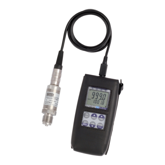
Intrinsically safe hand-held pressure indicator model CPH62I0-S1 with optional
model CPT62I0 reference pressure sensor
Operating instructions
Betriebsanleitung
EN
DE
Kapitel
Inhaltsverzeichnis

Verwandte Anleitungen für WIKA CPH62I0


Inhaltszusammenfassung für WIKA CPH62I0
- Seite 53 6.4.3 Messarten (rAtE) ....... .77 6.4.4 Mittelwertbildung ....... .78 WIKA Betriebsanleitung, Typ CPH62I0...
- Seite 54 10.1 Gesamte Messkette ....93 10.2 Digitales Anzeigegerät Typ CPH62I0 ....94 10.3 Referenz-Drucksensor Typ CPT62I0 .
-
Seite 55: Allgemeines
Das in der Betriebsanleitung beschriebene eigensichere Hand-Held Druckmessgerät ■ Typ CPH62I0-S1 oder CPH62I0-S2 wird nach dem aktuellen Stand der Technik konst- ruiert und gefertigt. Alle Komponenten unterliegen während der Fertigung strengen Qualitäts- und Umweltkriterien. Unsere Managementsysteme sind nach ISO 9001 und ISO 14001 zertifiziert. -
Seite 56: Kurzübersicht
Messbereich des jeweils angesteckten Drucksensors und gewährleistet eine hochgenaue Druckmessung. Neben Drucksensorik für Relativ- und Absolutdruck lässt sich mit dem CPH62I0-S2 und zwei angeschlossenen Drucksensoren auch Differenzdruck messen. Wählbare Druckeinheiten sind hierbei bar, mbar, psi, Pa, kPa, MPa, mmHg oder inHg. -
Seite 57: Lieferumfang
2. Kurzübersicht / 3. Sicherheit Nullpunktkorrektur, Alarm, Power-off, variable Messrate, Sea Level etc., ermöglichen den vielfältigen Einsatz des Hand-Held Druckmessgerätes. 2.3 Lieferumfang Hand-Held Druckmessgerät Typ CPH62I0-S1 oder CPH62I0-S2 inkl. 9-V-Blockbatterie ■ Ledertasche (Ex-Schutzhülle) ■ Ein Sensoranschlusskabel ca. 1,1 m (3,3 ft) pro Kanal ■... -
Seite 58: Bestimmungsgemäße Verwendung
3. Sicherheit 3.2 Bestimmungsgemäße Verwendung Das Hand-Held Druckmessgerät CPH62I0 kann als Kalibriergerät sowie für jede Anwen- dung, bei der eine genaue Druckmessung erforderlich ist, im explosionsgefährdeten Bereich verwendet werden. Zur Verwendung des CPH62I0 in explosionsgefährdeten Bereichen ist es zwingend notwendig, das Hand-Held Druckmessgerät in die mitgelieferte Ledertasche (Ex-Schutzhülle) zu stecken. -
Seite 59: Personalqualifikation
3.5 Beschilderung, Sicherheitskennzeichnungen 3.5.1 Typenschild Der Betreiber ist verpflichtet das Typenschild lesbar zu halten. Typenschild für Hand-Held Druckmessgerät Das Typenschild ist auf der Rückseite des Hand-Helds befestigt. 1 Produktname 2 Zulassungsrelevante Daten 3 Artikelnummer 4 Herstellungsdatum 5 Seriennummer WIKA Betriebsanleitung, Typ CPH62I0... -
Seite 60: Symbolerklärung
Vorschriften zur Installation und Einsatz in explosionsgefährdeten Bereichen (z. B. IEC 60079-14, NEC, CEC) einhalten. ▶ Der Betrieb der seriellen und analogen Schnittstelle ist im explosionsgefährdeten Bereich nicht zulässig! ▶ Nur Drucksensoren Typ CPT62I0 verwenden! WIKA Betriebsanleitung, Typ CPH62I0... -
Seite 61: Zugelassene Batterien
Temperaturklasseneinteilung und Umgebungstemperaturberei- che: Kennzeichnung Temperaturklasse Umgebungstemperaturbereich Hand-Held Druckmessgerät Typ CPH62I0-S1 oder CPH62I0-S2 II 2G Ex ib IIC T4 T1 ... T4 Ta = -10 ... +50 °C Referenz-Drucksensor Typ CPT62I0 II 2G Ex ib IIC T4 T1 ... -
Seite 62: Analogausgang
Für die elektrische Verbindung zwischen Drucksensor Typ CPT62I0 und Hand-Held ■ Druckmessgerät CPH62I0-S1 oder CPH62I0-S2 nur das hierfür vorgesehene original WIKA-Sensoranschlusskabel verwenden. Dies gilt ebenfalls für das Verlängerungska- bel, womit die maximal zulässige Gesamtkabellänge von knapp 5 m (16,4 ft) erreicht wird. -
Seite 63: Netzgerätebetrieb
Batterietyp Hersteller Batteriebezeichnung 6F22 GREENCELL, 9 V (1604G) 6LF22 SUPER Alkaline, 9 V (1604A) oder Duracell DURACELL PLUS, Alkaline, 9 V 6LR61 Varta Powerone Alkaline, 9 V (No. 4122) Varta INDUSTRIAL, Alkaline, 9 V (No. 4022) WIKA Betriebsanleitung, Typ CPH62I0... -
Seite 64: Aufbau Und Funktion
3 Logg-Pfeil: Logger ist bereit Pfeil blinkt: automatische Aufzeichnung (Logg CYCL) aktiv 4 Tara-Pfeil: Tara-Funktion ist aktiviert 5 SL-Pfeil: Höhenkorrektur (Sea Level) ist aktiviert 6 Anzeigepfeile für Messwerteinheiten 7 Anzeigeelemente zur Darstellung des Min-/Max-Messwertes, Differenz oder Hold WIKA Betriebsanleitung, Typ CPH62I0... -
Seite 65: Funktionstasten Und Bedienung
4.2 Funktionstasten und Bedienung Pos. Symbol Bedeutung Ein-/Aus-Taste Ein- und Ausschalten des CPH62I0-S1 oder CPH62I0-S2 Aufruf des Max.-Speichers ▲ Durch Drücken der Taste [MAX] wird der maximal gemessenen Wert angezeigt. Erneutes Drücken blendet ihn wieder aus. Zum Löschen des Max.-Wertes [MAX] für > 2 Sekunden drücken. -
Seite 66: Abkürzungen, Definitionen
Am oberen Ende des Gerätes befinden sich die Anschlussbuchsen CH1 und CH2 (CH2 nur bei 2-Kanal-Ausführung) zum Anschluss der Drucksensoren Typ CPT62I0 (siehe Kapitel 4.5 „Drucksensoren“) und die Buchse zum Anschluss des WIKA-Schnittstellenka- bels (siehe Kapitel 4.6 „Serielle oder analoge Schnittstelle“). -
Seite 67: Spannungsversorgung
Die jeweilige Betriebsart „Schnittstelle“ oder „Analogausgang“ muss konfigu- riert werden und beeinflusst die Batterielebensdauer! Typ CPH62I0-S1 Typ CPH62I0-S2 1 Schnittstellenanschluss oder optionaler Analogausgang 2 Anschluss Kanal 1 (nur mit CPH62I0-S1) 3 Anschluss Kanal 2 (nur mit CPH62I0-S2) 4 Anschluss Kanal 1 (nur mit CPH62I0-S2) 4.4 Spannungsversorgung GEFAHR! -
Seite 68: Drucksensoren
Hand-Held Druckmessgerät und den Referenz-Drucksensor beschädigen. ▶ Nur Referenz-Drucksensoren des Typs CPT62I0 verwenden! ▶ Nur das original Sensor-Anschlusskabel von WIKA für den Betrieb des Referenz-Drucksensors CPT62I0 verwenden. 4.5.1 Verfügbare Drucksensoren Das Hand-Held ist so konzipiert, dass alle Drucksensoren Typ CPT62I0 ohne Neuab- gleich angesteckt werden können. -
Seite 69: Drucksensoren Anschließen/Wechseln
Die Nichtbeachtung dieser Inhalte und Anweisungen kann zum Verlust des Explosionsschutzes führen. Durch Arbeiten in entzündlichen Atmosphären besteht Explosionsgefahr, die zum Tod führen kann. ▶ Der Betrieb der seriellen oder analogen Schnittstelle ist im explosionsgefährdeten Bereich nicht zulässig! WIKA Betriebsanleitung, Typ CPH62I0... - Seite 70 Kabels und einem 3,5 mm Stereo-Klinkenstecker am anderen Ende des Kabels. Das Kabel ist ca. 2 m (6,6 ft) lang. Die eigensichere Version CPH62I0-S1 oder CPH62I0-S2 befindet sich in einer Ledertasche (Ex-Schutzhülle). Der Schnittstellenanschluss befindet sich somit unter der Ex-Schutzhülle.
-
Seite 71: Transport, Verpackung Und Lagerung
1. Das Gerät in eine antistatische Plastikfolie einhüllen. 2. Das Gerät mit dem Dämmmaterial in der Verpackung platzieren. 3. Bei längerer Einlagerung (mehr als 30 Tage) einen Beutel mit Trocknungsmittel der Verpackung beilegen. WIKA Betriebsanleitung, Typ CPH62I0... -
Seite 72: Inbetriebnahme, Betrieb
Buchse des Hand-Helds anstecken und sicherstellen dass eine volle 9-V-Blockbatterie eingelegt ist. Die Anschlussbuchsen sind entsprechend am Gerätegehäuse mit 1 oder 2 gekennzeich- net (nur bei CPH62I0-S2). Daneben befindet sich die serielle bzw. analoge Schnittstelle. 6.2 Betrieb Beim Einschalten wird, falls eine Loggerfunktion gewählt wurde, kurz die Uhrzeit angezeigt. -
Seite 73: Menüfunktionen
Sensor an Anschluss 2 werden die Einstellungen übernommen. 3) Ist die automatische Aufzeichnung aktiviert, können diese Menüpunkte nicht aufgerufen werden. Sollen diese verändert werden, muss der zyklische Datenlogger zunächst beendet werden (siehe Kapitel 6.5 „Bedienung der Loggerfunktion“). WIKA Betriebsanleitung, Typ CPH62I0... -
Seite 74: Bedeutung
3) Ist die automatische Aufzeichnung aktiviert, können diese Menüpunkte nicht aufgerufen werden. Sollen diese verändert werden, muss der zyklische Datenlogger zunächst beendet werden (siehe Kapitel 6.5 „Bedienung der Loggerfunktion“). 4) Wird eine Alarmfunktion über- oder unterschritten, wird diese durch ein „Hupen“ also ein Piepsen signalisiert. WIKA Betriebsanleitung, Typ CPH62I0... - Seite 75 2) Erscheint nur, wenn keine Daten im Logger gespeichert sind, siehe Kapitel 6.5 „Bedienung der Loggerfunktion“ 3) Ist die automatische Aufzeichnung aktiviert, können diese Menüpunkte nicht aufgerufen werden. Sollen diese verändert werden, muss der zyklische Datenlogger zunächst beendet werden (siehe Kapitel 6.5 „Bedienung der Loggerfunktion“). WIKA Betriebsanleitung, Typ CPH62I0...
-
Seite 76: Konfigurieren Des Gerätes
1 angeschlossen ist. Bei aktivierter „Sea Level“-Funktion wird unten in der Anzeige der Pfeil für ‚SL‘ angezeigt. Wurde die Höhe des Aufenthaltsortes über dem Meeresspiegel eingegeben, zeigt das Gerät jetzt den Absolutdruck auf Meereshöhe bezogen an. WIKA Betriebsanleitung, Typ CPH62I0... -
Seite 77: Messarten (Rate)
6.4.3.3 Schnelle Messung = Fast (rAtE-FASt) Die Messfrequenz beträgt > 1.000 Hz und das Messsignal wird gefiltert wiedergegeben. Dadurch ist es weniger störungsempfindlich und die kurze Spitzen werden herausgefil- tert. Ansonsten ist diese Funktion identisch zur „rAtE-P.dEt“. WIKA Betriebsanleitung, Typ CPH62I0... -
Seite 78: Mittelwertbildung
(Faktor ist in %): Angezeigter Wert = (gemessener Wert – Offset) * (1+Scal/100) Standardeinstellung ‚off‘ = 0.000, d.h. es wird keine Korrektur vorgenommen. Die Steigungskorrektur wird zusammen mit der Nullpunktkorrektur vor allem zum Abgleich von Sensorabweichungen verwendet. WIKA Betriebsanleitung, Typ CPH62I0... -
Seite 79: Abschaltverzögerung
Mit dAC.0 und dAC.1 kann der Analogausgang sehr einfach skaliert werden. ▶ Darauf achten, dass der Analogausgang nicht zu stark belastet wird, da sonst der Ausgangswert verfälscht werden kann und die Stromaufnahme des Gerätes entspre- chend steigt. WIKA Betriebsanleitung, Typ CPH62I0... -
Seite 80: Klinkensteckerbelegung
▶ Nur Stereo-Klinkenstecker sind zulässig. ▶ Nur das Original-Anschlusskabel von WIKA verwenden! 6.4.10 Alarm (AL.) Es sind 3 Einstellungen möglich: aus = „AL.oFF“, an = „AL.on“ oder an = „AL.no.So“. Bei folgenden Bedingungen wird bei aktiver Alarmfunktion „AL.on“ oder „AL.no.So“ ein Alarm ausgegeben: Untere „AL.Lo“... -
Seite 81: Bedienung Der Loggerfunktion
Hauptmenüs) steht die Hold-Funktion nicht zur Verfügung. Min.- und Max.-Wert sind dabei die minimal bzw. maximal gemessenen Druckwerte seit dem letzten Speichervorgang. Somit können sowohl der aktuelle Druckwert als auch vorhandene Druckschwankungen sehr genau analysiert werden. WIKA Betriebsanleitung, Typ CPH62I0... -
Seite 82: Einzelwerte Speichern (Func-Stor)
: Min.-Peak, Max.-Peak seit dem letzten Speichern ■ Uhrzeit und Datum zum Zeitpunkt des Speicherns ■ 1) Gilt nur für 2-Kanal-Version CPH62I0-S2 Bei jedem Speichern wird kurz „St.XX“ angezeigt. XX ist dabei die Nummer des Messer- gebnisses. Gespeicherte Daten löschen 1. -
Seite 83: Automatische Aufzeichnung Mit Einstellbarer Zykluszeit „Func-Cycl
- Sensor 2 : Min.-Peak, Max.-Peak seit dem letzten Speichern - Differenz Sensor 1 - Sensor 2 : momentaner Wert zum Zeitpunkt des Speicherns - Differenz Sensor 1 - Sensor 2 : Min.-Peak, Max.-Peak seit dem letzten Speichern WIKA Betriebsanleitung, Typ CPH62I0... - Seite 84 - Differenz Sensor 1 - Sensor 2 : arithmetischer Mittelwert seit dem letzten Speichern - Differenz Sensor 1 - Sensor 2 : Min.-Peak, Max.-Peak seit dem letzten Speichern 1) Gilt nur für 2-Kanal-Version CPH62I0-S2 Loggeraufzeichnung starten 1. Taste [STORE/QUIT] 2 Sekunden lang drücken. ⇒...
- Seite 85 2. Mit Taste [MIN] oder [MAX] die Anzeige umschalten. ⇒ Die Anzeige „Lo66 CLr“ erscheint: 3. Taste [STORE/QUIT] drücken. ⇒ Die Auswahl zum Löschen des Loggerspeichers wird angezeigt: 4. Mit Taste [MIN] oder [MAX] gewünschte Funktion auswählen. WIKA Betriebsanleitung, Typ CPH62I0...
-
Seite 86: Störungen
Gerät unverzüglich außer Betrieb setzen. ▶ Sicherstellen, dass kein Druck bzw. Signal mehr anliegt und gegen versehentliche Inbetriebnahme schützen. ▶ Kontakt mit dem Hersteller aufnehmen. ▶ Bei notwendiger Rücksendung die Hinweise unter Kapitel 9.2 „Rücksen- dung“ beachten. WIKA Betriebsanleitung, Typ CPH62I0... -
Seite 87: Maßnahmen
überprüfen und evtl. durch einen geeigneten Sensor ersetzen. - - - - Loggerdaten werden über die Schnitt- Sobald Übertragung beendet ist, - - - - stelle ausgelesen arbeitet Gerät wieder im normalen Messmodus, keine Abhilfe notwendig. WIKA Betriebsanleitung, Typ CPH62I0... - Seite 88 Anzeigebereich ist unterschritten. Prüfen: Anzeige unter -2000 (tara?) Err.4 ⇒ Wert ist zu tief! ⇒ Wert erhöhen Systemfehler Zur Reparatur einschicken. Err.7 Messwert konnte nicht berechnet Andere Einheit wählen. Err.11 werden. Überlauf ist aufgetreten. Andere Einheit wählen. WIKA Betriebsanleitung, Typ CPH62I0...
-
Seite 89: Wartung, Reinigung Und Rekalibrierung
Schutzausrüstung: Schutzhandschuhe und Schutzbrille Werkzeuge: Schraubenschlüssel oder Drehmomentschlüssel Kontaktdaten siehe Kapitel 1 „Allgemeines“ oder Rückseite der Betriebsan- leitung. 8.1 Wartung Das Hand-Held Druckmessgerät Typ CPH62I0 ist wartungsfrei. Reparaturen sind ausschließlich vom Hersteller durchzuführen. Ausgenommen ist der Austausch der Blockbatterie. 8.2 Batteriewechsel GEFAHR! Lebensgefahr durch Explosion Durch Arbeiten in entzündlichen Atmosphären besteht Explosionsgefahr, die... -
Seite 90: Reinigung
3. Ausgebautes Gerät spülen bzw. säubern, um Personen und Umwelt vor Gefährdung durch anhaftende Messstoffreste zu schützen. 8.4 Rekalibrierung DKD/DAkkS-Schein - amtliche Bescheinigungen: Es wird empfohlen, das Gerät in regelmäßigen Zeitabständen von ca. 12 Monaten durch den Hersteller rekalibrieren zu lassen. Die Grundeinstellungen werden wenn notwendig korrigiert. WIKA Betriebsanleitung, Typ CPH62I0... -
Seite 91: Demontage, Rücksendung Und Entsorgung
Schutzausrüstung: Schutzhandschuhe und Schutzbrille Werkzeuge: Schraubenschlüssel oder Drehmomentschlüssel WARNUNG! Körperverletzungen, Sach- und Umweltschäden durch Messstoffreste Messstoffreste am Hand-Held Druckmessgerät Typ CPH62I0 oder Referenz-Drucksensor Typ CPT62I0 können zur Gefährdung von Personen, Umwelt und Einrichtung führen. ▶ Angaben im Sicherheitsdatenblatt für den entsprechenden Messstoff beachten. -
Seite 92: Rücksendung
9. Demontage, Rücksendung und Entsorgung 9.2 Rücksendung Beim Versand des Gerätes unbedingt beachten: Alle an WIKA gelieferten Geräte müssen frei von Gefahrstoffen (Säuren, Laugen, Lösun- gen, etc.) sein und sind daher vor der Rücksendung zu reinigen. WARNUNG! Körperverletzungen, Sach- und Umweltschäden durch Messstoffreste Messstoffreste am Hand-Held Druckmessgerät Typ CPH62I0 oder... -
Seite 93: Technische Daten
Das Nichtbeachten der Angaben für den Einsatz in explosionsgefährdeten Bereichen führt zum Verlust des Explosionsschutzes. ▶ Nachfolgende Grenzwerte und technische Angaben einhalten. 10.1 Gesamte Messkette Hand-Held Druckmessgerät Typ CPH62I0 (gesamte Messkette) Messeingänge 1 Eingang bei CPH62I0-S1 2 Eingänge bei CPH62I0-S2 Messbereich... -
Seite 94: Digitales Anzeigegerät Typ Cph62I0
Druckarten Relativdruck, {Absolutdruck von 0 ... 25 bar abs. (0 ... 360 psi abs.) und Vakuummessbereiche von -1 ... +24 bar (-14,5 ... 550 psi)} Differenzdruckmessung nur mit CPH62I0-S2 und zwei angeschlos- senen Referenz-Drucksensoren Typ CPT62I0 Sensorkompatibilität Kompatibel mit Referenz-Drucksensoren Typ CPT62I0 10.2 Digitales Anzeigegerät Typ CPH62I0... -
Seite 95: Referenz-Drucksensor Typ Cpt62I0
10. Technische Daten Digitales Anzeigegerät Typ CPH62I0 Kommunikation Schnittstelle RS-232 oder USB via Schnittstellenkabel Analogausgang DC 0 ... 1 V; konfigurierbar (via Menü alternativ zur Schnittstelle aktivierbar) Gehäuse Material schlagfester ABS-Kunststoff, Folientastatur, Klarsichtscheibe, Ledertasche Elektrischer Anschluss Sensorkabel: Bajonettstecker, 7-polig Schnittstelle: Stereo-Klinkenstecker, 3,5 mm... -
Seite 96: Sicherheitstechnische Kennwerte
Relative Luftfeuchte 0 ... 95 % r. F. (nicht kondensierend) Gehäuse Material CrNi-Stahl Anschluss an das CPH62I0 via 1,1 m (3,3 ft) Sensoranschlusskabel (Plug-and-Play); Optional: Verlängerungskabel ca. 3,8 m (12,5 ft), Gesamtkabellän- ge ca. 5 m (16,4 ft) Schutzart IP65... -
Seite 97: Ex-Zulassungen
■ 10.6 Zertifikate/Zeugnisse Zertifikat Kalibrierung Standard: Kalibrierzertifikat 3.1 nach DIN EN 10204 Option: DKD/DAkkS-Kalibrierzertifikat Empfohlenes 1 Jahr (abhängig von den Nutzungsbedingungen) Rekalibrierungsintervall Zulassungen und Zertifikate siehe Internetseite Weitere technische Daten siehe WIKA-Datenblatt CT 11.02 und Bestellunterlagen. WIKA Betriebsanleitung, Typ CPH62I0... -
Seite 98: Abmessungen In Mm (In)
10. Technische Daten 10.7 Abmessungen in mm (in) Digitales Anzeigegerät CPH62I0-S1 oder CPH62I0-S2 36 (1,42) 71 (2,80) 25 (0,98) WIKA Betriebsanleitung, Typ CPH62I0... - Seite 99 10. Technische Daten Referenz-Drucksensor CPT62I0 Ø 27 (Ø 1.06) Ø 6 (Ø 0.24) Ø 17.5 (Ø 0.69) G 1/2 B WIKA Betriebsanleitung, Typ CPH62I0...
-
Seite 100: Zubehör
3,8 m (12,5 ft) auf ca. 5 m (16,4 ft) (Ex-Ausführung) Schnittstellenkabel für RS-232-Schnittstellen für USB-Schnittstellen Kalibriersoftware Datenlogger-Auswertesoftware GSoft Bestellangaben für Ihre Anfrage: 1. Bestellcode: CPH-A-6I ⇓ 2. Option: WIKA-Zubehör finden Sie online unter www.wika.de. WIKA Betriebsanleitung, Typ CPH62I0... -
Seite 101: Anlage 1: Eu-Konformitätserklärung Typ Cph62I0
Anlage 1: EU-Konformitätserklärung Typ CPH62I0 WIKA Betriebsanleitung, Typ CPH62I0... -
Seite 102: Anlage 2: Eu-Konformitätserklärung Typ Cpt62I0
Anlage 2: EU-Konformitätserklärung Typ CPT62I0 WIKA Betriebsanleitung, Typ CPH62I0... - Seite 104 WIKA subsidiaries worldwide can be found online at www.wika.com. WIKA-Niederlassungen weltweit finden Sie online unter www.wika.de. WIKA Alexander Wiegand SE & Co. KG Alexander-Wiegand-Straße 30 63911 Klingenberg • Germany Tel. +49 9372 132-0 +49 9372 132-406 info@wika.de www.wika.de WIKA operating instructions, model CPH62I0...