KEB Dynamic Line I Betriebsanleitung
Größe a1 f3

Verwandte Anleitungen für KEB Dynamic Line I

Inhaltszusammenfassung für KEB Dynamic Line I
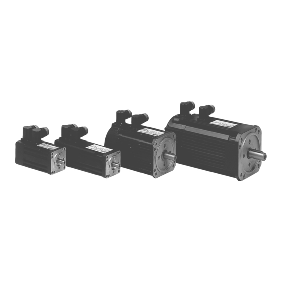
- Seite 1 B E T R I E B S A N L E I T U N G I N S T R U C T I O N M A N U A L Dynamic Line I Servomotore Größe A1…F3 Servo Motors Size A1…E3...
- Seite 2 Diese Anleitung beschreibt die Motoren der Reihe Dynamic Line II. Den Sicherheits- und Warnhinweisen in dieser An- leitung sowie in weiterer Dokumentation ist für einen sicheren Betrieb unbedingt Folge zu leisten. Die Nichtbeachtung der Sicherheitshinweise führt zum Verlust jeglicher Schadensersatzansprüche. Die in dieser Anleitung aufgeführten Si- cherheits- und Warnhinweise erheben keinen Anspruch auf Vollständigkeit.
-
Seite 3: Inhaltsverzeichnis
Inhaltsverzeichnis Allgemeines ..........4 Wartung und Reparatur ......25 Bestimmungsgemäße Verwendung ....4 Wartungsintervalle .......... 25 Sicherheitshinweise .......... 4 Technische Daten ........26 Transport und Verpackung ........ 5 Eigenkühlung ..........26 Einlagerung ............5 Fremdkühlung ..........35 Normen, Vorschriften, Bestimmungen ....5 Drehmoment-Drehzahl-Kennlinien ....38 EG Herstellererklärung ........ -
Seite 4: Allgemeines
Allgemeines Bestimmungsgemäße Verwendung Die Synchron-Servomotoren KEB COMBIVERT SM dienen zum Betrieb an digitalen Servostellern und sind für gewerbliche Anlagen bestimmt. Sie entsprechen den harmonisierten Normen der Reihe VDE 0530/EN 60034. Der Einsatz im Ex-Bereich ist verboten, sofern dies nicht ausdrücklich zugelassen ist (Zusatzhinweise beach- ten). -
Seite 5: Transport Und Verpackung
Allgemeines Der in die Wicklung eingebaute Thermofühler zum Schutz des Motors vor ther- mischer Überlastung bei langsamer Änderung ist anzuschließen und durch eine Schutz geeignete Schaltung auszuwerten. Achtung: Der Thermofühler stellt keinen allsei- tigen Schutz der Wicklung dar. Der Thermofühler stellt keinen allseitigen Schutz Motorwicklung der Wicklung dar. -
Seite 6: Eg Herstellererklärung
Die Inbetriebnahme (d.h. die Aufnahme der bestimmungsgemäßen Verwendung) der Motoren ist solange un- tersagt, bis festgestellt wurde, dass die Anlage oder Maschine den Bestimmungen der EG Richtlinie Maschinen 2006/42/EG sowie der EG Richtlinie EMV (2004/108/EG) entspricht. Bei Bedarf ist eine Herstellererklärung bei KEB erhältlich. D - 6... -
Seite 7: Produktbeschreibung
C: Bremse, öldichter Flansch IP65 (Radial-Wellendichtring) Kühlung 0: Selbstkühlung mit Flansch B5 1FT5 kompatibel 1: Fremdkühlung mit Flansch B5 1FT5 kompatibel 2: Selbstkühlung Fuss 3: Fremdkühlung Fuss Motortyp 0: Drehstromsynchronmotor Dynamic Line I Gerätetyp SM:Servomotor Baugröße/Baulänge A1…E3 D - 7... -
Seite 8: Motorübersicht
Produktbeschreibung Motorübersicht Stillstands- Bemessungsdrehmoment M [Nm] in Abhängigkeit drehmoment der Motorbemessungsdrehzahl Motortyp [Nm] bei 10 min 1.000 min 2.000 min 3.000 min 4.000 min 6.000 min A1.SM.000 0,34 0,32 A2.SM.000 0,50 0,48 A3.SM.000 0,65 A4.SM.000 B1.SM.000 0,65 B2.SM.000 B3.SM.000 C1.SM.000 0,95 0,75 C2.SM.000... -
Seite 9: Grundausstattung Der Servomotoren
Produktbeschreibung Grundausstattung der Servomotoren Standard Option Bauform IM B5 (IM V1, IM V3) Schutzart IP 65 Wellendurchführung IP 64 IP 65 Motorart Permanenterregter Synchron-Servomotor Magnetmaterial Neodym-Eisen-Bor Bemessunsdaten gültig für S1- Betrieb (Dauerbetrieb) Schwingstärkestufe Flanschgenauigkeit Isolierstoffklasse 155 (F); Drahtisolation in Klasse 180 (H) Thermistor (PTC) 150°C (mit verstärkter KTY 84;... -
Seite 10: Projektierung
Zur Überprüfung bzw. Optimierung kann nun mit den realen Motordaten noch einmal gegengerechnet werden. 2.5.2 Auswahl des Servostellers Die Auswahl des Servostellers erfolgt nun über den max. Kurzzeitgrenzstrom und dem Ausgangsbemessungs- strom. Alternativ stellt KEB für registrierte Benutzer im Internet und Service&Downloads den „Motorkonfigurator“ zur Verfügung. MLmax • Stillstandsdauerstrom (I Max. Kurzzeitgrenzstrom =... -
Seite 11: Aufbau Und Definition
Produktbeschreibung 2.6 Aufbau und Definition Die Servomotoren der Reihe SM.5 sind 6- bzw. 8-polige permanenterregte Synchronmaschinen mit sinusförmig induzierter Spannung. Durch Verwendung der neuartigen Kompaktspulentechnik wird eine extreme Leistungs- dichte der Motoren erreicht. 2.6.1 Antriebsseite und Drehsinn Antriebsseite des Motors In der DIN EN 60034-7 werden die beiden Enden eines Motors wie folgt festgelegt: D (Drive End): in der Regel die Antriebsseite (AS) des Motors. -
Seite 12: Wicklung Und Isolationssystem
Produktbeschreibung 2.6.3 Wicklung und Isolationssystem Mit den verwendeten Isolierstoffen wird die Isolierstoffklasse 155 (F) nach EN 60034 erreicht. Damit kann die Wicklungsübertemperatur bei einer Kühlmitteltemperatur von +40°C maximal 105 K betragen. Zur Erhöhung der Zuverlässigkeit der Motoren werden im System auch Isolierstoffe mit dem Temperaturprofil TI 200 der Klasse 180 (H) verwendet. -
Seite 13: Fremdlüfter
Produktbeschreibung 2.6.5 Fremdlüfter Zur Fremdbelüftung der Motoren SM.51 finden Axiallüfter mit Einphasenspaltpolmotor Verwendung, dessen An- schlussdaten mit auf dem Motortypenschild ausgewiesen sind. Der zum Anschluss notwendige Gegenstecker ist im Lieferumfang des Motors enthalten. Motortyp Bemessungsspannung Bemessungsstrom Schutzart CxSM.51 230 V (+10 % / -10 %) 50/60 Hz 0,12 A IP 54 DxSM.51... - Seite 14 Produktbeschreibung AxSM.50 und BxSM.50 CxSM.5x, DxSM.5x und ExSM.5x mit Einzelkaltleiter STM 150 E mit Drillingskaltleiter STM 150 D R [Ω] R [Ω] 1 x 4000 3 x 4000 1 x 1330 3 x 1330 1 x 550 3 x 550 1 x 250 3 x 250 T [°C]...
-
Seite 15: Drehzahl- Und Lagemesssystem / Resolver
Produktbeschreibung DxSM.50 ExSM.51 t [s] t [s] FxSM.51 t [s] Legende Motor betriebswarm empfohlene Stromgrenze Motor kalt 2.6.7 Drehzahl- und Lagemesssystem / Resolver Zur Messung der Drehzahl bzw. Lage sind Motoren der Reihe SM.5 standardmäßig mit 2-poligen Resolvern ausgerüstet. Technische Daten des Resolvers Polzahl Übersetzungsverhältnis K 0,5 ±5%... -
Seite 16: Betriebsbedingungen
Betriebsbedingungen Betriebsbedingungen Schutzart Die Gehäuse der Servomotoren SM.5 sind generell in der Schutzart IP 65 nach DIN EN 60034-5 ausgeführt (Op- tion Fremdlüfter: IP 54). Die Abdichtung der Motorwelle kann der folgenden Übersicht entnommen werden. Abdichtung der Welle Schutzart Anwendungshinweise Nur geringe Feuchtigkeitseinwirkung im Bereich der Welle und des Spaltdichtung Flansches zulässig. -
Seite 17: Zulässige Axial- Und Querkräfte
Betriebsbedingungen Brand- und An den Motoren können Oberflächentemperaturen von über 100°C auftreten. Es Verbrennungs- dürfen dort keine temperaturempfindlichen Teile anliegen oder befestigt werden. schutz Gegebenenfalls sind Schutzmaßnahmen gegen Berühren vorzusehen. Leistungs- Aufgrund unterschiedlicher Taktfrequenzen der Leistungsendstufen der Umrichter reduzierung und der damit verbundenen unterschiedlichen Verluste durch den Stromoberwel- aufgrund von lengehalt kann eine Leistungsreduzierung notwendig sein. -
Seite 18: Wellenbeanspruchung
Betriebsbedingungen 3.3.2 Wellenbeanspruchung Die Dauerfestigkeit der Welle und die Lebensdauer des Lagers bestimmen die zulässige Querkraft F am D(rive- End)-seitigen Wellenende. = 0,35 • F 3.3.3 Abtriebselement Der kleinstmögliche Wirkkreisdurchmesser des Abtriebselementes läßt sich wie folgt berechnen: Wirkungskreisdurchmesser des Abtriebselementes k •... -
Seite 19: Horizontale Gebrauchslage
Betriebsbedingungen 3.3.5 Horizontale Gebrauchslage c + p + 0,5 • L Wirkt die Querkraft F nicht bei x = L/2, treten veränderte Radialkräfte auf: • –––––––––––– c + p + x Wirkt die Axialkraft F nicht mittig auf die Welle, so wirken die Radialanteile dieser Kraft: •... -
Seite 20: Anschluss
Anschluss Anschluss Der Anschluss muss so erfolgen, dass eine dauerhaft sichere, elektrische Verbindung aufrechterhal- ten wird. Auf eine sichere Schutzleiterverbindung ist zu achten. Durch Verdrehen der Flanschdosen können beliebige Kabelabgangsrichtungen eingestellt werden (jeweils um 90° drehbar). Bei unsachgemäßer Ausführung der Arbeiten ist die Schutzart IP65 nicht mehr gewährleistet. Finden Steckersysteme Anwendung, wird die Schutzart IP65 nur bei vorschriftsmäßig verkabeltem und fest angezogenem Gegenstecker erreicht. -
Seite 21: Geberanschluss
Anschluss Geberanschluss 4.3.1 Resolver Resolverstecker Ansicht Signal Farbe • Winkeldose SIN- • drehbar COS+ rosa • 12-polig REF+ gelb • Stecker REF- grün SIN+ blau COS- grau Alle anderen Kontakte sind nicht be- legt. Blick auf die Anschlussstifte am Motor Geberkabel A-Servo 00F50C1-0yyy F5-Multi 00F50C1-1yyy... -
Seite 22: Endat
Anschluss 4.3.3 EnDat EnDat-Stecker Ansicht Signal Farbe • Winkeldose weiß • drehbar Clock+ schwarz • 17-polig Clock- violett • Stecker braun blau Data+ grau grün gelb Data- rosa Blick auf die Anschlussstifte Alle anderen Kontakte sind nicht be- am Motor legt. -
Seite 23: Fremdlüfteranschluss
Anschluss Fremdlüfteranschluss Fremdlüfteranschluss Ax…Dx.SM.5 Ex.SM.5 Blick auf die Anschlussstifte am Motor Anschlussbelegung 1 x 230 V AC 3 x 400 V AC Schutzleiter Schutzleiter D - 23... -
Seite 24: Inbetriebnahme
Anschluss Inbetriebnahme Vorbereitungen Vor der ersten Inbetriebnahme bzw. nach Revisionen ist noch einmal die Ausführung der kompletten Anlage aus mechanischer als auch elektrischer Sicht zu kontrollieren. Überprüfen, dass • die Montage sowie die Betriebsbedingungen mit den Daten laut Leistungsschildangaben übereinstimmen. •... -
Seite 25: Wartung Und Reparatur
Anschluss Wartung und Reparatur Sorgfältige und regelmäßige Wartung und Inspektionen sind erforderlich, um Störungen frühzeitig zu erkennen und zu beseitigen, bevor diese zu umfangreichen Schäden führen. Reparaturen dürfen nur vom Hersteller bzw. durch von ihm autorisierte Reparatur- stellen vorgenommen werden. Unbefugtes Öffnen und unsachgemäße Eingriffe Reparaturen können zu Körperverletzungen bzw. -
Seite 26: Eigenkühlung
Technische Daten Technische Daten Eigenkühlung Servomotor Ax.SM.000-yyyy Baugröße (x) Drehzahl- u. Spannungsvariante (y) 6200 6400 6200 6400 6200 6400 6200 6400 Stillstandsdrehmoment Md0 0,34 0,50 0,65 Stillstandsstrom Id0 0,85 1,50 Bemessungsdaten Bemessungsspannung UN Bemessungsdrehmoment MN 0,32 0,48 Bemessungstrom IN Bemessungsdrehzahl nN min-1 6000 6000... -
Seite 27: Technische Daten
Technische Daten Bx.SM.000-yyyy Servomotor Baugröße (x) Drehzahl- u. Spannungsvariante (y) 4200 4400 6200 6400 4200 4400 6200 6400 4200 4400 6200 6400 Stillstandsdrehmoment M 0,65 Stillstandsstrom I A 1,9 Bemessungsdaten Bemessungsspannung U V 230 400 230 230 400 230 230 400 Bemessungsdrehmoment M Bemessungstrom I A 2,0... - Seite 28 Technische Daten Cx.SM.000-yyyy Servomotor Baugröße (x) Drehzahl- u. Spannungsvariante (y) 3200 3400 4200 4400 6200 6400 3200 3400 4200 4400 Stillstandsdrehmoment M 0,95 Stillstandsstrom I A 1,5 Bemessungsdaten Bemessungsspannung U V 230 Bemessungsdrehmoment M 0,75 Bemessungstrom I A 1,4 0,75 Bemessungsdrehzahl n 3000 4000...
- Seite 29 Technische Daten Cx.SM.000-yyyy 6200 6400 3200 3400 4200 4400 6200 6400 3200 3400 4200 4400 6200 6400 13,7 6000 3000 4000 6000 3000 4000 6000 1,25 1,22 1,47 1,76 1,57 1,88 1,88 33,0 55,7 69,4 118,0 52,6 90,8 35,4 61,4 67,7 113,0 53,0...
- Seite 30 Technische Daten Dx.SM.000-yyyy Servomotor Baugröße (x) Drehzahl- u. Spannungsvariante (y) 3200 3400 4200 4400 6200 6400 3200 3400 4200 4400 Stillstandsdrehmoment M Stillstandsstrom I 10,2 11,6 Bemessungsdaten Bemessungsspannung U Bemessungsdrehmoment M 3,50 Bemessungstrom I 2,80 10,5 Bemessungsdrehzahl n 3000 4000 6000 3000 4000...
- Seite 31 Technische Daten Dx.SM.000-yyyy 6200 6400 3200 3400 4200 4400 6200 6400 3200 3400 4200 4400 16,0 12,4 17,0 22,6 13,6 14,2 18,2 11,6 10,9 13,5 12,7 12,2 13,5 6000 3000 4000 6000 3000 4000 35,5 57,8 69,3 119,8 50,5 88,2 37,9 63,1 73,1...
- Seite 32 Technische Daten Ex.SM.000-yyyy Servomotor Baugröße (x) Drehzahl- u. Spannungsvariante (y) 2200 2400 3200 3400 4200 4400 2200 2400 3200 3400 Stillstandsdrehmoment M Stillstandsstrom I 10,7 13,3 Bemessungsdaten Bemessungsspannung U Bemessungsdrehmoment M 12,2 11,0 Bemessungstrom I 10,4 Bemessungsdrehzahl n 2000 3000 4000 2000 3000...
- Seite 33 Technische Daten Ex.SM.000-yyyy 4200 4400 2200 2400 3200 3400 4200 4400 2200 2400 3200 3400 17,8 10,0 11,7 17,6 10,3 21,9 13,5 16,5 23,2 14,4 16,5 14,6 21,4 15,5 10,6 14,0 10,4 13,0 13,3 4000 2000 3000 4000 2000 3000 79,8 128,1 143,1...
- Seite 34 Technische Daten Fx.SM.000-yyyy Servomotor Baugröße (x) Drehzahl- u. Spannungsvariante (y) 1400 2400 3400 4400 1400 2400 3400 1400 2400 3400 Stillstandsdrehmoment M Stillstandsstrom I 11,1 17,0 22,2 17,0 22,3 32,2 23,1 30,8 46,2 Bemessungsdaten Bemessungsspannung U Bemessungsdrehmoment M Nm 22,5 21,5 20,0 16,0 42,0...
-
Seite 35: Fremdkühlung
Technische Daten Fremdkühlung Servomotor Dx.SM.000-yyyy Baugröße (x) Drehzahl- u. Spannungsvariante (y) 3400 4400 6400 3400 4400 6400 3400 4400 6400 3400 4400 Stillstandsdrehmoment M 10,5 14,5 18,0 Stillstandsstrom I A 4,1 14,2 10,4 14,1 19,7 12,3 16,8 Bemessungsdaten Bemessungsspannung U Bemessungsdrehmoment M Nm 5,5 12,2... - Seite 36 Technische Daten Servomotor Ex.SM.000-yyyy Baugröße (x) Drehzahl- u. Spannungsvariante (y) 2400 3400 4400 2400 3400 4400 2400 3400 4400 2400 3400 Stillstandsdrehmoment M 12,9 21,5 Stillstandsstrom I A 7,1 10,1 12,8 10,7 15,5 20,0 14,1 21,6 23,1 21,4 27,8 Bemessungsdaten Bemessungsspannung U Bemessungsdrehmoment M Nm 11,2...
- Seite 37 Technische Daten Servomotor Fx.SM.000-yyyy Baugröße (x) Drehzahl- u. Spannungsvariante (y) 1400 2400 3400 4400 1400 2400 3400 1400 2400 3400 Stillstandsdrehmoment M Stillstandsstrom I A 12,3 16,6 25,4 33,2 25,5 33,5 48,3 34,8 Bemessungsdaten Bemessungsspannung U Bemessungsdrehmoment M Nm 35,4 31,7 58,2 92,8...
-
Seite 38: Drehmoment-Drehzahl-Kennlinien
Technische Daten Drehmoment-Drehzahl-Kennlinien 7.3.1 Motoren der 230 V-Klasse ⓐ ⓑ ⓐ: Kurzzeitbetrieb ⓑ: Dauerbetrieb Artikelnummer Artikelnummer Mmax Mmax [Nm] [Nm] [1/min] [Nm] [Nm] [1/min] A1.SM.000-6200 0,34 0,32 6000 5950 9500 D1.SM.000-3200 18,9 3000 2550 4000 A2.SM.000-6200 0,48 6000 6950 9500 D1.SM.000-4200 18,9 4000... -
Seite 39: Motoren Der 400 V-Klasse
Technische Daten 7.3.2 Motoren der 400 V-Klasse ⓐ ⓑ ⓐ: Kurzzeitbetrieb ⓑ: Dauerbetrieb Artikelnummer Artikelnummer Mmax Mmax [Nm] [Nm] [1/min] [Nm] [Nm] [1/min] A1.SM.000-6400 0,34 0,32 6000 7550 11950 D2.SM.000-6400 31,5 6000 6550 8050 A2.SM.000-6400 0,48 6000 6900 10050 D3.SM.000-3400 3000 2850 3850... -
Seite 40: Optionen
Technische Daten Optionen 7.4.1 Haltebremse Motortyp Ax.SM.001-xx00 Bx.SM.001-xx00 Cx.SM.001-xx00 Haftmoment [Nm] Trägheitsmoment [kgcm 0,067 0,183 max. Drehzahl [min 10.000 10.000 10.000 Gewicht [kg] 0,18 0,30 0,50 Bemessungsspg. 24 (+6%, -10%) Bemessungsstrom 0,46 0,50 0,75 Abfallzeit t2 [ms] Ansprechverzug t11 [ms] Anzugszeit t1 [ms] Leistung... -
Seite 41: Anhang
Normen EN 60204-1, EN 60034, EN 292-1 und EN 292-2 werden angewendet. Eine entsprechende Konformitätserklärung kann bei Bedarf über unser Internetportal bezogen werden. 8.1.3 UL-Kennzeichnung Eine Abnahme gemäß UR und cUR ist bei KEB Servomotore auf dem Typenschild durch nebenstehendes Logo sowie durch das E-File ge- kennzeichnet. - Seite 42 Notizen D - 42...
- Seite 84 +39 02 33535311 • fax: +39 02 33500790 net: www.keb.it • mail: kebitalia@keb.it KEB Power Transmission Technology (Shanghai) Co.,Ltd. No. 435 QianPu Road, Songjiang East Industrial Zone, KEB Japan Ltd. CHN-201611 Shanghai, P.R. China 15–16, 2–Chome, Takanawa Minato-ku fon: +86 21 37746688 • fax: +86 21 37746600 J–Tokyo 108-0074...