Herunterladen Diese Seite drucken
Vorschau ausblenden Andere Handbücher für RTN/M2LAR:

Werbung

Verfügbare Sprachen

Verfügbare Sprachen

Mounting Instructions | Montageanleitung |
Notice de montage | Instrucciones de montaje
English
Deutsch
Français
Español
RTN/M2...
RTN/M2LAR, RTN/M2LA,
RTN/M2LBR, RTN/M2LB

Werbung

loading

Inhaltszusammenfassung für HBM RTN/M2LAR

  • Seite 1 Mounting Instructions | Montageanleitung | Notice de montage | Instrucciones de montaje English Deutsch Français Español RTN/M2… RTN/M2LAR, RTN/M2LA, RTN/M2LBR, RTN/M2LB...
  • Seite 2 Tel. +49 6151 803-0 Fax +49 6151 803-9100 info@hbm.com www.hbm.com Mat.: 7-2001.1088 DVS: A01867_02_YS0_02 HBM: public 07.2021 E Hottinger Baldwin Messtechnik Subject to modifications. All product descriptions are for general information only. They are not to be understood as a guarantee of quality or durability.
  • Seite 3 Mounting Instructions | Montageanleitung | Notice de montage | Instrucciones de montaje English Deutsch Français Español RTN/M2… RTN/M2LAR, RTN/M2LA, RTN/M2LBR, RTN/M2LB...
  • Seite 4 ..........Specifications of the RTN/M2L... weighing modules ..RTN/M2… A01867_02_YS0_02 HBM: public...
  • Seite 5 Residual dangers The scope of supply and performance of the weighing modules covers only a small area of weighing technology. In addition, equipment planners, installers and operators should plan, implement and respond to the safety engineering RTN/M2… A01867_02_YS0_02 HBM: public...
  • Seite 6 In such cases the operator must take appropriate safety measures. With environmental conditions that cannot be clearly defined, HBM recom­ mends to provide the load cells and weighing modules with a protective coating which matches these conditions (after mounting) in order to prevent the influ­...
  • Seite 7 This marking draws your attention to important information about the product or about handling the Important product. Emphasis Italics are used to emphasize and highlight text and See…. references to other chapters and external documents. RTN/M2… A01867_02_YS0_02 HBM: public...
  • Seite 8 General General HBM offers the RTN/M2(L)... weighing module for RTN load cells with max. capacities of 1 t ... 33 t. The ”L” in the type designation signifies that the mod­ ule has been fitted with a stay rod. “A” signifies rubber‐metal bearing, “B”...
  • Seite 9 RTN/M2LB) is used which allows for horizontal shifting of the load applied. The weighing modules are completely fitted with a load cell dummy that can be loaded, with a ground cable, and a securing device for transport. RTN/M2… A01867_02_YS0_02 HBM: public...
  • Seite 10 (e.g. deflections) under load. S In order to provide for fitting and assembly free from any constraining forces, the mounting bores on the basic construction and the tank connec­ tion must be sufficiently aligned. RTN/M2… A01867_02_YS0_02 HBM: public...
  • Seite 11 Five plates max. are to be fitted underneath the upper module plate, and five plates max. between the base and the cross bracket of the anti‐liftoff device Important Ensure that all screws are fitted with U‐washers. RTN/M2… A01867_02_YS0_02 HBM: public...
  • Seite 12 (only up to 4.7 t 5 plates max. for height adjustment Centering disc max. capacity) (only up to 4.7 t max. capacity) Cross‐bracket (Anti‐liftoff device) Lateral stops Fig. 4.1 Fitting of the spacer plates with 4.7 t version RTN/M2… A01867_02_YS0_02 HBM: public...
  • Seite 13 5 plates max. for height adjustment Air gap: 1 mm Dummy Bearing 5 plates max. for height adjustment Cross‐bracket (Anti‐liftoff device) Lateral stops Fig. 4.2 Fitting of the spacer plates with 10 t ... 33 t version RTN/M2… A01867_02_YS0_02 HBM: public...
  • Seite 14 Mounting of load cells up to a max. capacity of 4.7 t: see Fig. 4.1 S Remove the anti‐liftoff device by undoing the 2 hexagonal screws S Loosen the lateral stops S Use a suitable lifting device to lift the respective tank base by approx. 10 mm RTN/M2… A01867_02_YS0_02 HBM: public...
  • Seite 15 Mounting of load cells with a max. capacity of 10 t, 15 t, 22 t and 33 t: see Fig. 4.2 S Remove the anti‐liftoff device by undoing the 2 hexagonal screws S Use a suitable lifting device to lift the respective tank base by approx. 10 mm RTN/M2… A01867_02_YS0_02 HBM: public...
  • Seite 16 (see chapter 7 on page 22). Notice Precautions during operation: S Deposits such as dirt or corrosion particles from the tank can falsify measurement results. S The limits for movability and loading capacity specified in the Specifications must not be exceeded. RTN/M2… A01867_02_YS0_02 HBM: public...
  • Seite 17 S The movement tolerance of the stay rod should be checked regularly and readjusted, if necessary. RTN/M2… A01867_02_YS0_02 HBM: public...
  • Seite 18 RTN/M2LA - Version with rubber‐metal bearing Max. capacity 1 t ... 4,7 t max. 5 spacer plates only version with stay rod View from above Perspective view View from below Dimensions in mm (1mm = 0.03937 inches) RTN/M2… A01867_02_YS0_02 HBM: public...
  • Seite 19 RTN/M2LA - Version with rubber‐metal bearing Max. capacity 10 t ... 22 t max. 5 spacer plates only version with stay rod View from above Perspective view View from below Dimensions in mm (1mm = 0.03937 inches) RTN/M2… A01867_02_YS0_02 HBM: public...
  • Seite 20 Dimensions RTN/M2LA - Version with rubber‐metal bearing Max. capacity 33 t max. 5 spacer plates only version with stay rod View from above Perspective view View from below Dimensions in mm (1mm = 0.03937 inches) RTN/M2… A01867_02_YS0_02 HBM: public...
  • Seite 21 RTN/M2LB - Version with pendulum bearing Max. capacity 1 t ... 4.7 t max. 5 spacer plates only version with stay rod View from above Perspective view View from below Dimensions in mm (1mm = 0.03937 inches) RTN/M2… A01867_02_YS0_02 HBM: public...
  • Seite 22 RTN/M2LB - Version with pendulum bearing Max. capacity 10 t ... 22 t max. 5 spacer plates only version with stay rod View from above Perspective view View from below Dimensions in mm (1mm = 0.03937 inches) RTN/M2… A01867_02_YS0_02 HBM: public...
  • Seite 23 Dimensions RTN/M2LB - Version with pendulum bearing Max. capacity 33 t max. 5 spacer plates only version with stay rod View from above Perspective view View from below Dimensions in mm (1mm = 0.03937 inches) RTN/M2… A01867_02_YS0_02 HBM: public...
  • Seite 24 Neoprene (Chlorbutadien caoutchouc) Weight (with dummy), 10.5 21.5 44.5 approx. Min. lifting height for installing the load cell Height adjustment (spacer plates in scope of delivery) These specifications are based on DIN 18800 According to EN 10088-1 RTN/M2… A01867_02_YS0_02 HBM: public...
  • Seite 25 WITH stay rod 4.7 t stainless steel 1-RTN/M2AR4.7T WITHOUT stay rod 1-RTN/M2LAR22T WITH stay rod 10 t ... 22 t stainless steel 1-RTN/M2AR22T WITHOUT stay rod 1-RTN/M2LA33T WITH stay rod 33 t galvanized 1-RTN/M2A33T WITHOUT stay rod RTN/M2… A01867_02_YS0_02 HBM: public...
  • Seite 26 1 t ... 4.7 t stainless steel 1-RTN/M2BR4.7T/2 WITHOUT stay rod 1-RTN/M2LBR22T WITH stay rod 10 t ... 22 t stainless steel 1-RTN/M2BR22T WITHOUT stay rod 1-RTN/M2LB33T WITH stay rod 33 t galvanized 1-RTN/M2B33T WITHOUT stay rod RTN/M2… A01867_02_YS0_02 HBM: public...
  • Seite 27 Stay rod Load introduction 90° 90° Degree of freedom Attention: The represented bearing arrangements con­ sider only weighing‐techni­ cal criteria. The carrying and stability 90° 90° must be examined and guaranteed in each case by the operator. RTN/M2… A01867_02_YS0_02 HBM: public...
  • Seite 28 Specifications RTN/M2… A01867_02_YS0_02 HBM: public...
  • Seite 29 Mounting Instructions | Montageanleitung Notice de montage | Instrucciones de montaje English Deutsch Français Español RTN/M2… RTN/M2LAR, RTN/M2LA, RTN/M2LBR, RTN/M2LB...
  • Seite 30 ..........Technische Daten der Wägemodule RTN/M2L....RTN/M2… A01867_02_YS0_02 HBM: public...
  • Seite 31 Wägemodules beauftragt ist, muss die Montageanleitung und insbeson­ dere die sicherheitstechnischen Hinweise gelesen und verstanden haben. Restgefahren Der Leistungs‐ und Lieferumfang der Wägemodule deckt nur einen Teilbereich der Wägetechnik ab. Sicherheitstechnische Belange der Wägetechnik sind zusätzlich vom Anlagenplaner/Ausrüster/Betreiber so zu planen, zu realisieren RTN/M2… A01867_02_YS0_02 HBM: public...
  • Seite 32 Stähle und deren Schweißnähte angreifen. In die­ sem Fall sind von der Betreiberseite entsprechende Schutzmaßnahmen vorzu­ sehen. HBM empfiehlt bei nicht eindeutig geklärten Umweltbedingungen, die Wäge­ zellen und Wägemodule mit einem, auf die Bedingungen abgestimmten Schutzanstrich (im montierten Zustand), zu versehen, um den Einfluss von aggressiven Medien fernzuhalten.
  • Seite 33 Diese Kennzeichnung weist auf wichtige Informa­ tionen zum Produkt oder zur Handhabung des Pro­ Wichtig duktes hin. Hervorhebung Kursive Schrift kennzeichnet Hervorhebungen im Siehe … Text und kennzeichnet Verweise auf Kapitel, Bilder oder externe Dokumente und Dateien. RTN/M2… A01867_02_YS0_02 HBM: public...
  • Seite 34 
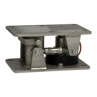
Allgemeines Allgemeines HBM bietet das Wägemodul RTN/M2(L)AR..., RTN/M2(L)BR... für RTN‐Wäge­ zellen in den Nennlastbereichen 1t...33t an. Das “L” in der Typenbezeichnung bedeutet, das Wägemodul ist mit einem Lenker ausgerüstet. “A” bedeutet mit Gummi‐Metall‐Lager, “B” steht für Pendellager. Produktvarianten RTN/M2LA... Bestellnummer...
  • Seite 35 Als Lasteinleitungselement in die Wägezelle dient ein Gummi‐Metall‐ Lager (bei RTN/M2LA), bzw. ein Pendellager (bei RTN/M2LB), welches hori­ zontale Verschiebungen der aufgebrachten Last ermöglicht. Die Wägemodule sind komplett mit einem belastbaren Wägezellen‐Dummy, Erdungskabel und Transportsicherung montiert. RTN/M2… A01867_02_YS0_02 HBM: public...
  • Seite 36 S Das Fundament/Basiskonstruktion, sowie die Anbindung des Aufbaus müs­ sen genügend steif sein, um unzulässige Verformungen (z.B. Durchbiegun­ gen) unter Belastung zu vermeiden. S Um eine von Zwangskräften freie Montage zu ermöglichen, müssen die Be­ festigungsbohrungen an Basiskonstruktion und Behälteranschluss ausrei­ chend fluchten. RTN/M2… A01867_02_YS0_02 HBM: public...
  • Seite 37 Ausrichten des Moduls. Maximal fünf Bleche sind unter der oberen Modul­ platte und maximal fünf Bleche zwischen dem Sockel und Riegel der Abhebe­ sicherung unterzulegen. Wichtig Achten Sie darauf, dass alle Schrauben mit U‐Scheiben montiert sind. RTN/M2… A01867_02_YS0_02 HBM: public...
  • Seite 38 Höhenausgleich Luftspalt 1 mm Lager Dummy Grundplatte (nur bis Nennlast 4,7 t) Zentrierscheibe (nur max. 5 Bleche für Höhenausgleich bis Nennlast 4,7 t) Querriegel (Abhebesicherung) seitliche Anschläge Abb. 4.1 Montage der Ausgleichsbleche bei Ausführung 4,7 t RTN/M2… A01867_02_YS0_02 HBM: public...
  • Seite 39 Montagevorbereitung max. 5 Bleche für Obere Modulplatte Höhenausgleich Luftspalt 1 mm Dummy Lager max. 5 Bleche für Höhenausgleich seitliche Anschläge Querriegel (Abhebesicherung) Abb. 4.2 Montage der Ausgleichsbleche bei Ausführung 10 t .. 33 t RTN/M2… A01867_02_YS0_02 HBM: public...
  • Seite 40 Montage der Wägezelle Zum Einbau der Wägezelle in das Wägemodul muss der bereits vorhandene Dummy demontiert werden. Montage der Wägezellen bis 4,7 t Nennlast: (siehe Abb. 4.1) S Entfernen der Abhebesicherung durch Lösen der zwei Sechskantschrauben RTN/M2… A01867_02_YS0_02 HBM: public...
  • Seite 41 (Spalte von den Anschlägen) sind den technischen Daten Kapitel 7 zu ent­ nehmen. Die Lenker sind ab Werk bereits voreingestellt, so dass in Lenker­ richtung die Lasteinleitungsteile mit der Wägezelle fluchten. Falls doch eine Nachstellung erforderlich werden sollte, sind die Gelenkköpfe anschließend sorgfältig zu kontern. RTN/M2… A01867_02_YS0_02 HBM: public...
  • Seite 42 Gelenkköpfe anschließend sorgfältig zu kontern. Hinweise zur Justage der horizontalen Anschläge Die horizontale Beweglichkeit ist durch das Gummi‐Metall‐ oder Pendellager gewährleistet. Die Horizontalanschläge sind entsprechend der zulässigen max. seitlichen Verschiebung (siehe Kap. 7) einzustellen. RTN/M2… A01867_02_YS0_02 HBM: public...
  • Seite 43 Lenkerrichtung wirken, sind durch entsprechende Aus­ richtung der anderen Module zu vermeiden oder durch anderweitige An­ schläge bzw. Vorrichtungen aufzunehmen. S Das Bewegungsspiel des Lenkers sollte regelmäßig kontrolliert und gegebe­ nenfalls nachjustiert werden. RTN/M2… A01867_02_YS0_02 HBM: public...
  • Seite 44 Abmessungen Abmessungen RTN/M2LA - Ausführung mit Gummi‐Metall‐Lager Nennlast 1 t ... 4,7 t max. 5 Ausgleichsbleche nur bei Ausführung mit Lenker Ansicht von oben Perspektivische Ansicht Ansicht von unten Abmessungen in mm RTN/M2… A01867_02_YS0_02 HBM: public...
  • Seite 45 Abmessungen RTN/M2LA - Ausführung mit Gummi‐Metall‐Lager Nennlast 10 t ... 22 t max. 5 Ausgleichsbleche nur bei Ausführung mit Lenker Ansicht von oben Perspektivische Ansicht Ansicht von unten Abmessungen in mm RTN/M2… A01867_02_YS0_02 HBM: public...
  • Seite 46 Abmessungen RTN/M2LA - Ausführung mit Gummi‐Metall‐Lager Nennlast 33 t max. 5 Ausgleichsbleche nur bei Ausführung mit Lenker Ansicht von oben Perspektivische Ansicht Ansicht von unten Abmessungen in mm RTN/M2… A01867_02_YS0_02 HBM: public...
  • Seite 47 Abmessungen RTN/M2LB - Ausführung mit Pendellager max. 5 Ausgleichsbleche Nennlast 1 t ... 4,7 t nur bei Ausführung mit Lenker Ansicht von oben Perspektivische Ansicht Ansicht von unten Abmessungen in mm RTN/M2… A01867_02_YS0_02 HBM: public...
  • Seite 48 Abmessungen RTN/M2LB - Ausführung mit Pendellager Nennlast 10 t ... 22 t max. 5 Ausgleichsbleche nur bei Ausführung mit Lenker Ansicht von oben Perspektivische Ansicht Ansicht von unten Abmessungen in mm RTN/M2… A01867_02_YS0_02 HBM: public...
  • Seite 49 Abmessungen RTN/M2LB - Ausführung mit Pendellager Nennlast 33 t max. 5 Ausgleichsbleche nur bei Ausführung mit Lenker Ansicht von oben Perspektivische Ansicht Ansicht von unten Abmessungen in mm RTN/M2… A01867_02_YS0_02 HBM: public...
  • Seite 50 Stahl galv. verzinkt Metallteile Gummi‐Metall‐Lager Neopren (Chlorbutadien‐Kautschuk) Gewicht (mit Dummy), ca. 10,5 21,5 44,5 Minimale Hubhöhe zum Einbau der WZ Höhenausgleich durch mit­ gelieferte Beilegebleche Die Angaben erfolgen auf Basis der DIN 18800 Nach EN 10088‐1 RTN/M2… A01867_02_YS0_02 HBM: public...
  • Seite 51 1-RTN/M2AR2.2T OHNE Lenker 1-RTN/M2LAR4.7T MIT Lenker 4,7 t Nichtrostender Stahl 1-RTN/M2AR4.7T OHNE Lenker 1-RTN/M2LAR22T MIT Lenker 10 t ... 22 t Nichtrostender Stahl 1-RTN/M2AR22T OHNE Lenker 1-RTN/M2LA33T MIT Lenker 33 t Galvanisch verzinkt 1-RTN/M2A33T OHNE Lenker RTN/M2… A01867_02_YS0_02 HBM: public...
  • Seite 52 1-RTN/M2LBR4.7T/2 MIT Lenker 1 t ... 4,7 t Nichtrostender Stahl 1-RTN/M2BR4.7T/2 OHNE Lenker 1-RTN/M2LBR22T MIT Lenker 10 t ... 22 t Nichtrostender Stahl 1-RTN/M2BR22T OHNE Lenker 1-RTN/M2LB33T MIT Lenker 33 t Galvanisch verzinkt 1-RTN/M2B33T OHNE Lenker RTN/M2… A01867_02_YS0_02 HBM: public...
  • Seite 53 120° 120° 120° Lenker Lasteinleitung Freiheitsgrad 90° 90° Achtung: Die dargestellten Lagerord­ nungen berücksichtigen nur wägetechnische Gesicht­ spunkte. 90° 90° Die Trag‐ und Standsicher­ heit muss in jedem Fall vom Betreiber geprüft und sicher­ gestellt werden. RTN/M2… A01867_02_YS0_02 HBM: public...
  • Seite 54 Technische Daten RTN/M2… A01867_02_YS0_02 HBM: public...
  • Seite 55 Mounting Instructions | Montageanleitung | Notice de montage | Instrucciones de montaje English Deutsch Français Español RTN/M2… RTN/M2LAR, RTN/M2LA, RTN/M2LBR, RTN/M2LB...
  • Seite 56 ..........Caractéristiques techniques des modules de pesage RTN/M2..RTN/M2… A01867_02_YS0_02 HBM: public...
  • Seite 57 Toute personne chargée de l'installation, de la mise en service, de la mainte­ nance ou de la réparation d'un module de pesage de cuves doit impérati­ vement avoir lu et compris la notice de montage et notamment les consignes de sécurité. RTN/M2… A01867_02_YS0_02 HBM: public...
  • Seite 58 Lorsque les conditions environnantes n'ont pas été rendues claires et distinctes, HBM recommande d'appliquer un enduit de protection sur les pesons et les modules de pesages qui convient à ces conditions (en état monté) pour éviter l'influence des milieus agressifs. Prêtez attention à la stabi­...
  • Seite 59 Consignes de sécurité Prévention des accidents Bien que la charge de rupture corresponde à un multiple de la pleine échelle, il convient de respecter les règlements relatifs à la prévention des accidents du travail des associations correspondantes. RTN/M2… A01867_02_YS0_02 HBM: public...
  • Seite 60 Ce marquage signale que des informations importantes concernant le produit ou sa Important manipulation sont fournies. Mise en valeur Pour mettre en valeur certains mots du texte, Voir … ces derniers sont écrits en italique. RTN/M2… A01867_02_YS0_02 HBM: public...
  • Seite 61 Généralités Généralités Pour la famille de pesons RTN, HBM propose maintenant un module à intégrer baptisé RTN/M2(L)..., pour des capacités maxi de 1 à 33 tonnes. Le “L” dans la désignation signifie qu'il s'agit d'un module avec tirant transversal. Le “A”...
  • Seite 62 Les modules de pesage sont livrés entièrement montés avec un faux peson qui peut être chargé, un câble de mise à la terre et une sécurité de transport. RTN/M2… A01867_02_YS0_02 HBM: public...
  • Seite 63 être suffisamment rigide(s), pour être en mesure d'éviter toute déformation ou flexion sous la charge. S Les percages de fixation sur le bâti de base et les raccordements sur le réservoir doivent être alignés le mieux possible pour éviter l'introduction de contraintes de montage. RTN/M2… A01867_02_YS0_02 HBM: public...
  • Seite 64 à‐dire à l'aligner verticalement. On ne pourra mettre en place respectivement que cinq tôles sous la plaque module supérieure et autant entre le socle et le verrou de la sécurité anti‐soulèvement. Information Veiller à ce que toutes les vis soient montées avec des rondelles en U. RTN/M2… A01867_02_YS0_02 HBM: public...
  • Seite 65 Rondelle de centrage (sur 5 tôles, maxi, pour la com­ modules à capacité maxi 4,7t) pensation en hauteur Verrou transversal (Sécurité anti‐soulèvement) Butées latérales Fig. 4.1 Montage des tôles de compensation avec la version 4,7 t RTN/M2… A01867_02_YS0_02 HBM: public...
  • Seite 66 Interstice: 1 mm Mannequin Palier 5 tôles, maxi, pour la compensation en hauteur Butées latérales Verrou transversal (Sécurité anti‐soulèvement) Fig. 4.2 Montage des tôles de compensation avec la version 10 t ... 33 t RTN/M2… A01867_02_YS0_02 HBM: public...
  • Seite 67 Montage du peson Pour installer le peson dans le module de pesage, il faut d'abord démonter le faux peson en place. RTN/M2… A01867_02_YS0_02 HBM: public...
  • Seite 68 Chapitre 7, pour les valeurs du décalage transversal maxi admissible (distance des butées). Les tirants ont été ajusté à l'usine afin que les éléments d'introduction des charges s'alignent au peson. Si un rajustement s'avère nécessaire, les rotules doivent ensuite être bloquées soigneusement. RTN/M2… A01867_02_YS0_02 HBM: public...
  • Seite 69 Ajustage des butées latérales La capabilité de supporter ces mouvements dans le plan horizontal est garantie par le palier élastomère ou oscillant. Les butées latérales doivent être ajustées conformement au décalage transversal maxi admissible (voir Chapitre 7). RTN/M2… A01867_02_YS0_02 HBM: public...
  • Seite 70 être évités par l'alignement adéquat des autres modules, ou par la mise en place d'autres butées ou dispositifs analogues S Vérifier périodiquement le jeu du tirant et, le cas échéant, rajuster celui‐ci. RTN/M2… A01867_02_YS0_02 HBM: public...
  • Seite 71 Dimensions Dimensions RTN/M2LA - version avec palier élastomère Capacité maxi 1 t ... 4,7 t 5 tôles de compensation, max. seulement version avec contrefléau Vue de dessus Vue perspective Vue de dessous Dimensions en mm RTN/M2… A01867_02_YS0_02 HBM: public...
  • Seite 72 Dimensions RTN/M2LA - version avec palier élastomère Capacité maxi 10 t ... 22 t 5 tôles de compensation, max. seulement version avec contrefléau Vue de dessus Vue perspective Vue de dessous Dimensions en mm RTN/M2… A01867_02_YS0_02 HBM: public...
  • Seite 73 Dimensions RTN/M2LA - version avec palier élastomère Capacité maxi 33 t 5 tôles de compensation, max. seulement version avec contrefléau Vue de dessus Vue perspective Vue de dessous Dimensions en mm RTN/M2… A01867_02_YS0_02 HBM: public...
  • Seite 74 Dimensions RTN/M2LA - version avec palier oscillant 5 tôles de compensation, max. Capacité maxi 1 t ... 4,7 t seulement version avec contrefléau Vue de dessus Vue perspective Vue de dessous Dimensions en mm RTN/M2… A01867_02_YS0_02 HBM: public...
  • Seite 75 Dimensions RTN/M2LA - version avec palier oscillant Capacité maxi 10 t ... 22 t 5 tôles de compensation, max. seulement version avec contrefléau Vue de dessus Vue perspective Vue de dessous Dimensions en mm RTN/M2… A01867_02_YS0_02 HBM: public...
  • Seite 76 Dimensions RTN/M2LA - version avec palier oscillant 5 tôles de compensation, max. Capacité maxi 33 t seulement version avec contrefléau Vue de dessus Vue perspective Vue de dessous Dimensions en mm RTN/M2… A01867_02_YS0_02 HBM: public...
  • Seite 77 Poids (avec faux peson), 10,5 21,5 44,5 approx. Hauteur de levage mini pour le montage du peson Compensation de hauteur par les tôles de compensation fournies Les valeurs indiquées sont basées sur DIN 18800 Selon EN 10088‐1 RTN/M2… A01867_02_YS0_02 HBM: public...
  • Seite 78 1-RTN/M2AR2.2T SANS tirant 1-RTN/M2LAR4.7T AVEC tirant 4,7 t acier inoxydable 1-RTN/M2AR4.7T SANS tirant 1-RTN/M2LAR22T AVEC tirant 10 t ... 22 t acier inoxydable 1-RTN/M2AR22T SANS tirant 1-RTN/M2LA33T AVEC tirant 33 t acier étamé 1-RTN/M2A33T SANS tirant RTN/M2… A01867_02_YS0_02 HBM: public...
  • Seite 79 1-RTN/M2LBR4.7T/2 AVEC tirant 1 t ... 4,7 t acier inoxydable 1-RTN/M2BR4.7T/2 SANS tirant 1-RTN/M2LBR22T AVEC tirant 10 t ... 22 t acier inoxydable 1-RTN/M2BR22T SANS tirant 1-RTN/M2LB33T AVEC tirant 33 t acier étamé 1-RTN/M2B33T SANS tirant RTN/M2… A01867_02_YS0_02 HBM: public...
  • Seite 80 Attention: Les dispositions des pali­ ers représentées ne con­ sidèrent que les aspects de pesage. La sécurité de support et la stabilité stati­ 90° 90° que doivent en tout cas être vérifiées et assurées par l'opérateur. RTN/M2… A01867_02_YS0_02 HBM: public...
  • Seite 81 Mounting Instructions | Montageanleitung | Notice de montage | Instrucciones de montaje English Deutsch Français Español RTN/M2… RTN/M2LAR, RTN/M2LA, RTN/M2LBR, RTN/M2LB...
  • Seite 82 ..........Características técnicas del módulo de pesaje RTN/M2L..RTN/M2… A01867_02_YS0_02 HBM: public...
  • Seite 83 Cualquier persona encargada de la instalación, puesta en funcionamiento, mantenimiento o reparación de un módulo de pesaje, deberá haber leído y entendido las instrucciones de montaje, especialmente las indicaciones téc­ nicas de seguridad. RTN/M2… A01867_02_YS0_02 HBM: public...
  • Seite 84 Si esto fuera inevitable, el explotador deberá tomar las medidas de protección pertinentes. HBM recomienda en condiciones ambientales no especificadas aplicar una capa de pintura protectora determinada según las condiciones sobre las células de carga y módulos de pesaje una vez montados a fin de evitar la influencia de medios agresivos.
  • Seite 85 Instrucciones de seguridad Prevención de accidentes Aunque la carga de rotura indicada supera con creces el valor límite del campo de medida, deben respetarse las normas específicas de prevención de acci­ dentes de los sindicatos. RTN/M2… A01867_02_YS0_02 HBM: public...
  • Seite 86 Esta identificación indica información importante so­ bre el producto o su utilización. Importante Cursiva La letra en cursiva indica el énfasis en el texto y Véase… señala referencias a los capítulos, imágenes o do­ cumentos y archivos externos. RTN/M2… A01867_02_YS0_02 HBM: public...
  • Seite 87 Generalidades Generalidades HBM ofrece el módulo de pesaje RTN/M2(L)AR.., RTN/M2(L)BR... para la célula de carga RTN en los márgenes de carga nominal de 1 t hasta 33 t. Una “L” en la denominación del tipo significa que el módulo de pesaje está...
  • Seite 88 RTN/M2LB), los cuales permiten los desplazamientos horizontales de la carga aplicada. Los módulos de pesaje se suministran completamente mon­ tados, con una resistente célula de carga postiza, cable de puesta a tierra y protección para el transporte. RTN/M2… A01867_02_YS0_02 HBM: public...
  • Seite 89 S Para permitir un montaje libre de fuerzas de ligadura, los taladros de mon­ taje de la estructura base y la conexión del contenedor deben estar bien alineados. RTN/M2… A01867_02_YS0_02 HBM: public...
  • Seite 90 Se pueden colocar un máximo de 5 placas de­ bajo de la placa módulo superior y un máximo de 5 placas entre el zócalo y travesaño de la seguridad de levantamiento. Importante Verificar que todos los tornillos cuenten con arandelas. RTN/M2… A01867_02_YS0_02 HBM: public...
  • Seite 91 5 placas para nivelar alturas Arandela de centrado nominal 4,7 t) (solo hasta carga nominal 4,7 t) Travesaño (seguridad de levantamiento) Topes laterales Fig. 4.1 Montaje de las placas niveladoras en la versión de 4,7 t RTN/M2… A01867_02_YS0_02 HBM: public...
  • Seite 92 5 placas para nivelar alturas Separación: 1 mm Postiza Cojinete máx. 5 placas para nivelar alturas Topes laterales Travesaño (seguridad de levantamiento) Fig. 4.2 Montaje de las placas niveladoras en la versión de 10 t a 33 t RTN/M2… A01867_02_YS0_02 HBM: public...
  • Seite 93 Para montar la célula de carga en el módulo de pesaje hay que desmontar la célula de carga postiza presente. Montaje de la célula de carga hasta 4,7 t de carga nominal: (consultar Fig. 4.1) S Retirar la seguridad de levantamiento aflojando los dos tornillos hexagona­ les. RTN/M2… A01867_02_YS0_02 HBM: public...
  • Seite 94 7. Las bielas vienen ajustadas de fábrica de modo que, en el sentido de la biela, las piezas de introducción de carga están alineadas con la célula de carga. En el caso de que se necesitara un reajuste, se deberán bloquear las rótulas posteriormente. RTN/M2… A01867_02_YS0_02 HBM: public...
  • Seite 95 Recomendaciones para el ajuste horizontal de los topes La movibilidad horizontal está garantizada mediante el cojinete goma‐metal o el cojinete de péndulo. Los topes horizontales se deben ajustar conforme al desplazamiento lateral máximo permitido (consultar el capítulo 7). RTN/M2… A01867_02_YS0_02 HBM: public...
  • Seite 96 S Los desplazamientos horizontales que exceden el valor máximo permitido y que no actúan en el sentido de la biela, deben evitarse alineando corres­ pondientemente los otros módulos o utilizando otros topes o dispositivos. S Controlar y reajustar regularmente el juego de movimiento de la biela. RTN/M2… A01867_02_YS0_02 HBM: public...
  • Seite 97 Dimensiones Dimensiones Versión RTN/M2LA con cojinete goma‐metal Carga nominal 1 t ... 4,7 t máx. 5 placas niveladoras solo en la versión con biela Vista desde arriba Vista con perspectiva Vista desde abajo Dimensiones n mm RTN/M2… A01867_02_YS0_02 HBM: public...
  • Seite 98 Dimensiones Versión RTN/M2LA con cojinete goma‐metal Carga nominal 10 t ... 22 t máx. 5 placas niveladoras solo en la versión con biela Vista desde arriba Vista con perspectiva Vista desde abajo Dimensiones n mm RTN/M2… A01867_02_YS0_02 HBM: public...
  • Seite 99 Dimensiones Versión RTN/M2LA con cojinete goma‐metal Carga nominal 33 t máx. 5 placas niveladoras solo en la versión con biela Vista desde arriba Vista con perspectiva Vista desde abajo Dimensiones n mm RTN/M2… A01867_02_YS0_02 HBM: public...
  • Seite 100 Dimensiones Versión RTN/M2LB con cojinete de péndulo máx. 5 placas niveladoras Carga nominal 1 t ... 4,7 t solo en la versión con biela Vista desde arriba Vista con perspectiva Vista desde abajo Dimensiones n mm RTN/M2… A01867_02_YS0_02 HBM: public...
  • Seite 101 Dimensiones Versión RTN/M2LB con cojinete de péndulo Carga nominal 10 t ... 22 t máx. 5 placas niveladoras solo en la versión con biela Vista desde arriba Vista con perspectiva Vista desde abajo Dimensiones n mm RTN/M2… A01867_02_YS0_02 HBM: public...
  • Seite 102 Dimensiones Versión RTN/M2LB con cojinete de péndulo Carga nominal 33 t máx. 5 placas niveladoras solo en la versión con biela Vista desde arriba Vista con perspectiva Vista desde abajo Dimensiones n mm RTN/M2… A01867_02_YS0_02 HBM: public...
  • Seite 103 Cojinete goma‐metal Neopreno (caucho de cloropreno) Peso (con postiza), aprox. 10,5 21,5 44,5 Mín. altura elevación hasta montaje de célula de carga Nivelación de alturas me­ diante placas suministra­ Datos conforme a DIN 18800 Conforme EN 10088‐1 RTN/M2… A01867_02_YS0_02 HBM: public...
  • Seite 104 1-RTN/M2AR2.2T SIN biela 1-RTN/M2LAR4.7T CON biela 4,7 t acero inoxidable 1-RTN/M2AR4.7T SIN biela 1-RTN/M2LAR22T CON biela 10 t ... 22 t acero inoxidable 1-RTN/M2AR22T SIN biela 1-RTN/M2LA33T CON biela 33 t galvanizado 1-RTN/M2A33T SIN biela RTN/M2… A01867_02_YS0_02 HBM: public...
  • Seite 105 Versión 1-RTN/M2LBR4.7T/2 CON biela 1 t ... 4,7 t acero inoxidable 1-RTN/M2BR4.7T/2 SIN biela 1-RTN/M2LBR22T CON biela 10 t ... 22 t acero inoxidable 1-RTN/M2BR22T SIN biela 1-RTN/M2LB33T CON biela 33 t galvanizado 1-RTN/M2B33T SIN biela RTN/M2… A01867_02_YS0_02 HBM: public...
  • Seite 106 90° 90° Atención: La colocación de cojinetes se representa solo desde el punto de vista del pesaje. La seguridad en cuanto la capacidad de soporte y 90° 90° estabilidad debe verificarse y garantizarse por el explotador. RTN/M2… A01867_02_YS0_02 HBM: public...
  • Seite 107 Características técnicas RTN/M2… A01867_02_YS0_02 HBM: public...
  • Seite 108 HBM Test and Measurement Tel. +49 6151 803-0 Fax +49 6151 803-9100 info@hbm.com measure and predict with confidence...

Diese Anleitung auch für:

Rtn/m2laRtn/m2lbrRtn/m2lb