MICRO-EPSILON optoCONTROL 1201 Betriebsanleitung
Inhaltsverzeichnis
Verfügbare Sprachen
Verfügbare Sprachen
Quicklinks
Kapitel
Inhaltsverzeichnis

Verwandte Anleitungen für MICRO-EPSILON optoCONTROL 1201


Inhaltszusammenfassung für MICRO-EPSILON optoCONTROL 1201
- Seite 1 Betriebsanleitung Operating Instructions optoCONTROL 1200/1201 ODC1200 ODC1200/90 ODC1201...
-
Seite 3: Inhaltsverzeichnis
Inbetriebnahme ..............................18 Versorgungsspannung ............................ 18 LED‘s, Potentiometer optoCONTROL 1200 ....................19 LED‘s, Potentiometer optoCONTROL 1200/90 ....................20 LED‘s, Potentiometer optoCONTROL 1201 ....................21 Ein- und Ausgänge ............................22 Grenzwertausgang ............................24 Analogausgang ..............................25 Hinweise für den Betrieb ......................26 Fremdlicht ................................ - Seite 4 Haftung für Sachmängel ......................27 Service, Reparatur ........................27 Außerbetriebnahme, Entsorgung .................... 28 Anhang ............................28 optoCONTROL 1200/1201...
-
Seite 5: Sicherheit
Sicherheit Sicherheit Die Sensorhandhabung setzt die Kenntnis der Betriebsanleitung voraus. Verwendete Zeichen In dieser Betriebsanleitung werden folgende Bezeichnungen verwendet: Zeigt eine gefährliche Situation an, die zu geringfügigen oder mittelschweren Verletzungen führt, falls diese nicht vermieden wird. Zeigt eine Situation an, die zu Sachschäden führen kann, falls diese nicht vermieden wird. -
Seite 6: Hinweise Zur Ce-Kennzeichnung
Produkte, die das CE-Kennzeichen tragen, erfüllen die Anforderungen der zitierten EU-Richtlinien und die dort aufgeführten harmonisierten europäischen Normen (EN). Die EU-Konformitätserklärung wird gemäß der EU-Richtlinie, Artikel 10, für die zuständige Behörde zur Verfügung gehalten bei MICRO-EPSILON Eltrotec GmbH Manfred-Wörner-Straße 101 73037 Göppingen / Deutschland Das Messsystem ist ausgelegt für den Einsatz im Industriebereich und erfüllt die Anforderungen. -
Seite 7: Bestimmungsgemäße Verwendung
Sicherheit Bestimmungsgemäße Verwendung - Das Messsystem optoCONTROL 120x ist für den Einsatz im Industriebereich konzipiert. - Es wird eingesetzt zur Durchmesser-, Spalt-, Kanten- und Lichtmengenmessung. - Das Messsystem darf nur innerhalb der in den technischen Daten angegebenen Werte betrieben werden, siehe Kap. -
Seite 8: Laserklasse
Laserklasse Laserklasse Die Lichtquelle des optoCONTROL120x besteht aus einem Halbleiterlaser. Die Wellenlänge beträgt 670 nm (sichtbar/rot) mit einer maximalen optischen Ausgangsleistung von ≤ 0,39 mW. Die Sensoren sind in die Laserklasse 1 eingeordnet. Die zugängliche Strahlung ist unter vorhersehbaren Bedingungen ungefährlich. Bei Lasereinrichtungen der Klasse 1 kann eine Beeinträchtigung des Farbsehens und Belästigung nicht aus- geschlossen werden, z.B. -
Seite 9: Funktionsprinzip, Technische Daten
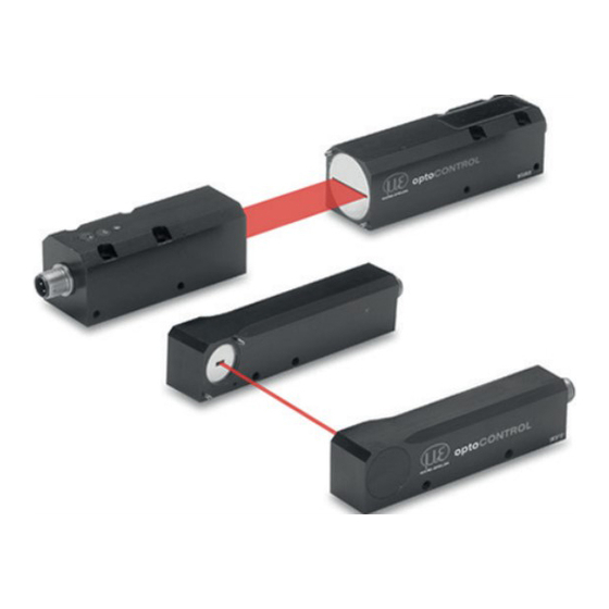
Funktionsprinzip, Technische Daten Funktionsprinzip, Technische Daten Funktionsprinzip Das optoCONTROL 120x basiert auf dem Prinzip der Lichtmengenmessung. Das Licht einer roten Laserdiode wird durch eine Optik zu einem parallelen Lichtvorhang aufgefächert, der auf die Empfängereinheit gerichtet wird. In der Empfängereinheit wird das Licht über verschiedene Filter und Optiken durch eine Präzisions- blende auf einen lichtempfindlichen Detektor geführt. -
Seite 10: Technische Daten
Funktionsprinzip, Technische Daten Technische Daten Modell ODC 1200 (axiale Ausführung) ODC 1200/90 (90 ° Ausführung) ODC 1201 Messbereich Grenzfrequenz 100 kHz (-3 db) Kleinstes detektierbares 1 % d.M. 0,02 0,05 0,16 0,02 0,05 0,16 Objekt Abstand Lichtquelle - Empfänger min. 20 mm bis max. 5 m (Freiraum) Linearität % d.M. -
Seite 11: Lieferung
Lieferung Lichtquelle ca. 150 g ca. 170 g ca. 260 g Gewicht (ohne Kabel) Empfänger ca. 120 g ca. 160 g ca. 220 g Schutzgrad IP 67 d.M. = des Messbereichs Die angegebenen Daten gelten für eine konstante Raumtemperatur von 20 °C, nach einer Warmlaufzeit von 30 min, im Bereich 10 ... -
Seite 12: Installation Und Montage
Installation und Montage Installation und Montage Der Sensor optoCONTROL 120x ist ein optisches System, mit dem im mm-Bereich gemessen wird. Achten Sie bei Montage und Betrieb des Sensors auf eine sorgsame Behandlung! Sensormontage Befestigen Sie den Sensor ausschließlich an den vorhandenen Bohrungen auf einer ebenen Fläche. Klem- mungen jeglicher Art sind nicht gestattet. - Seite 13 Installation und Montage Direktverschraubung 1 Gehäuse Einschraubtiefe Schraube Anziehdrehmoment pro Schraube Minimum Maximum ISO 4762 - A2 µ= 0,12 ODC1200-...-T ODC1200-...-R ODC1200-90-...-T ODC1200-90-...-R ODC1201-...-T ODC1201-...-R Direktverschraubung 2 Gehäuse Einschraubtiefe Schraube Anziehdrehmoment pro Schraube Minimum Maximum ISO 4762 - A2 µ= 0,12 ODC1200-...-T ODC1200-...-R ODC1200-90-...-T...
- Seite 14 Installation und Montage Blendenmaße (A x B) in mm Modell Sender Empfänger ODC1200-2 2 x 2 2 x 0,3 ODC1200-5 5 x 2 5 x 0,3 Lichtquelle Empfänger ODC1200-10 10 x 2 10 x 0,3 ODC1200-16 16 x 2 16 x 0,3 M4 x 5 M4 x 5 Laserlicht...
- Seite 15 Installation und Montage Lichtquelle Empfänger ø 4,1 ø 4,1 Laserlicht max. 5000 M4 x 6 M4 x 6 Abb. 5 Maßzeichnung ODC 1201, Messbereiche 20/30 mm, Abmessungen in mm, nicht maßstabsgetreu Modell Sender Empfänger ODC1201-20 20 x 2 20 x 0,3 Blendenmaße (A x B) in mm ODC1201-30...
- Seite 16 Installation und Montage Lichtquelle Empfänger Laserlicht M4 x 5 M4 x 5 M5 x 8 max. 5000 M5 x 8 Blendenmaße (A x B) in mm Modell Sender Empfänger ODC1200/90-2 2 x 2 2 x 0,3 ODC1200/90-5 5 x 2 5 x 0,3 ODC1200/90-10 10 x 2...
-
Seite 17: Elektrische Anschlüsse, Versorgungs- Und Ausgangskabel
Installation und Montage Elektrische Anschlüsse, Versorgungs- und Ausgangskabel Die Betriebsspannung wird vorzugsweise über ein abgeschirmtes Kabel angeschlossen, z.B. über das Versorgungskabel PC1200-5. Führen Sie den Kabelschirm auf eine Potentialausgleichsklemme in der Nähe des Netzteiles. 26,5 Biegeradius PC1200: minimal 52 mm ø... -
Seite 18: Betrieb
Betrieb Betrieb Inbetriebnahme Montieren Sie Lichtquelle und Empfänger entsprechend den Montagevorschriften, siehe Kap. Verbinden Sie das System mit nachfolgenden Anzeige- oder Überwachungseinheiten und der Stromver- sorgung, siehe Kap. 6.6. Die Laserdiode in der Lichtquelle ist aktiv, wenn die Versorgungsspannung eingeschaltet ist, siehe Kap. 6.6. Der Sensor benötigt für genaue Messungen eine Einlaufzeit von typisch 1 min. -
Seite 19: Led's, Potentiometer Optocontrol 1200
Betrieb LED‘s, Potentiometer optoCONTROL 1200 Versorgung Verstärkung Schaltschwelle Schaltzustand Einstellung Lichtquelle Empfänger Potentiometer Zustand Beschreibung Ausgang < 9,5 V Einstellung grün Ausgang > 9,5 V Analogspannung mit Verstärkungspoti auf 10 V einstellen gelb Analogspannung < Schaltschwelle Schaltzu- stand grün Analogspannung > Schaltschwelle Schaltschwelle Drehen im Uhrzeigersinn: Schaltschwelle erhöhen, Bereich 0 ... -
Seite 20: Potentiometer Zustand Beschreibung Rot
Betrieb LED‘s, Potentiometer optoCONTROL 1200/90 Versorgung Verstärkung Schaltschwelle Schaltzustand Einstellung Lichtquelle Empfänger Potentiometer Zustand Beschreibung Ausgang < 9,5 V Einstellung grün Ausgang > 9,5 V Analogspannung mit Verstärkungspoti auf 10 V einstellen gelb Analogspannung < Schaltschwelle Schaltzu- stand grün Analogspannung > Schaltschwelle Schaltschwelle Drehen im Uhrzeigersinn: Schaltschwelle erhöhen, Bereich 0 ... -
Seite 21: Led's, Potentiometer Optocontrol 1201
Betrieb LED‘s, Potentiometer optoCONTROL 1201 Einstellung Schaltzustand Verstärkung Schaltschwelle Versor- gung Lichtquelle Empfänger Potentiometer Zustand Beschreibung Schaltschwelle Drehen im Uhrzeigersinn: Schaltschwelle erhöhen, Bereich 0 ... 10 V Verstärkung Drehen im Uhrzeigersinn: Verstärkung erhöhen, Bereich 0 ... 10 V gelb Analogspannung < Schaltschwelle... -
Seite 22: Ein- Und Ausgänge
GND (0 V) schwarz Pin 2 verbunden mit 5 ... 24 VDC: Laser aus Schirm Gehäuse - - - MICRO-EPSILON Eltrotec GmbH empfiehlt die Verwendung des Versorgungs- und Ausgangskabels PC1200. Dieses Kabel ist als optionales Zubehör erhältlich. optoCONTROL 1200/1201 Seite 22... - Seite 23 Betrieb Empfänger Signal Farbe Versorgung +24 VDC PC120x Analogausgang 0 ... 10 VDC +12 ... +32 VDC braun < 100 mA Analogausgang weiß Last (0 ... 10 VDC) GND (0 V) blau Abb. 12 Anschluss Empfänger, Last mit GND verbunden, Digitalausgang schwarz (PNP aktiv Lichtmenge <...
-
Seite 24: Grenzwertausgang
Betrieb Grenzwertausgang Das optoCONTROL 1200/1200/90/1201 erlaubt eine unabhängige Einstellung des Grenzwertes, siehe Kap. und Kap. (für die Lage des Grenzwertpotentiometers). Die Schaltschwelle des Grenzwertausgangs ist frei schaltbar und wird in Abb. 14 bei 5 V aktiviert: - PNP aktiv, wenn Lichtmenge unter dem Grenzwert - NPN aktiv, wenn Lichtmenge über dem Grenzwert 10 V Abb. -
Seite 25: Analogausgang
Betrieb Analogausgang Das System gibt U aus, 10 V max. wenn sich kein Objekt im Kein Objekt zw. Strahlengang befindet. U Lichtquelle und kann mit dem Verstärkungs- Empfänger potentiometer eingestellt wer- 0 % Messbereich max. den und sollte 10 V betragen. Mit abnehmender Lichtmenge am Empfänger sinkt auch li- near die Ausgangsspannung. -
Seite 26: Hinweise Für Den Betrieb
Hinweise für den Betrieb Hinweise für den Betrieb Fremdlicht Vermeiden Sie die direkte Einstrahlung gerichteter Lichtquellen, wie z.B. Reflektorlampen oder Sonnenlicht, auf den Empfänger und das Messobjekt. Sorgen Sie durch geeignete Maßnahmen (matt schwarze Abschirmwände, Gehäuse usw.) dafür, dass möglichst kein Fremdlicht direkt in den Empfänger scheint. Dies gilt auch für wechselnde Reflexionen und Hintergründe, z.B. -
Seite 27: Haftung Für Sachmängel
Haftung für Sachmängel Alle Komponenten des Geräts wurden im Werk auf die Funktionsfähigkeit hin überprüft und getestet. Sollten jedoch trotz sorgfältiger Qualitätskontrolle Fehler auftreten, so sind diese umgehend an MICRO-EPSILON El- trotec zu melden. Die Haftung für Sachmängel beträgt 12 Monate ab Lieferung. Innerhalb dieser Zeit werden fehlerhafte Teile, ausgenommen Verschleißteile, kostenlos instandgesetzt oder ausgetauscht, wenn das Gerät kostenfrei an... -
Seite 28: Außerbetriebnahme, Entsorgung
Außerbetriebnahme, Entsorgung Außerbetriebnahme, Entsorgung Entfernen Sie das Versorgungs- und Ausgangskabel an der Lichtquelle und am Empfänger. Durch falsche Entsorgung können Gefahren für die Umwelt entstehen. Entsorgen Sie das Gerät, dessen Komponenten und das Zubehör sowie die Verpackungsmaterialien entsprechend den einschlägigen landesspezifischen Abfallbehandlungs- und Entsorgungsvorschriften des Verwendungsgebietes. - Seite 29 Anhang ODC1200/90 Zubehör für C-Rahmen Montage in Verbindung mit Justageplatten: BR1200L220 Klammer zur Montage als C-Rahmen, Höhe 220 mm, 2 St. erforderlich BR1200L320 Klammer zur Montage als C-Rahmen, Höhe 320 mm, 2 St. erforderlich ODC1202-L100 Montageschiene für ODC1202, Länge 400 mm; Max.