Herunterladen Diese Seite drucken
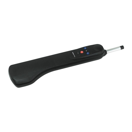
Simrad TP10 Handbuch
Vorschau ausblenden Andere Handbücher für TP10:

Werbung

Verfügbare Sprachen

Verfügbare Sprachen

TP10, TP22, TP32
Manuel Utilisateur
FRANÇAIS
simrad-yachting.com

Werbung

loading

Inhaltszusammenfassung für Simrad TP10

  • Seite 1 TP10, TP22, TP32 Manuel Utilisateur FRANÇAIS simrad-yachting.com...
  • Seite 2 Copyright © 2014 Navico Holding AS. Garantie Le contrat de garantie est un document fourni indépendamment de cette notice. Pour toute demande de garantie, veuillez consulter le site Web concernant votre appareil: www.simrad-yachting.com Préface | TP10, TP22 & TP32 Manuel Utilisateur...
  • Seite 3 Raccordement du TP au bus SimNet Interfaçage via NMEA Antiparasitage Compensation automatique du compas Annexe Conseils d’utilisation Recherche de panne Phrases NMEA en réception Pièces de rechange et accessoires Accessoires de pose Dimensions Caractéristiques techniques Préface | TP10, TP22 & TP32 Manuel Utilisateur...
  • Seite 4 Généralités Introduction Les pilotes automatiques Simrad TP10, TP22 et TP32 conviennent à la plupart des voiliers à barre franche jusqu’à 12 m (39 ft) de longueur hors-tout. Combinaison d’une électronique très sophistiquée gérée par un logiciel avancé et d’une puissante mécanique, ils atteignent un niveau de performance élevé...
  • Seite 5 Les données de cap transmises par le Tillerpilot ne peuvent être affichées sur un instrument que si aucun capteur de compas n’est connecté au réseau. En effet, les capteurs compas SimNet sont toujours prioritaires comme source de données de cap. Généralités | TP10, TP22 & TP32 Manuel Utilisateur...
  • Seite 6 ¼ Remarque: Le touche sur le TP22 et TP32 est marquée sur le TP10. Ces touches sont citées dans ce manuel là où la fonction s’applique. Mode Veille En mode Veille, le vérin peut être entré et sorti manuellement en appuyant sur les touches fléchées Bâbord ( ) et Tribord ( ), ce qui...
  • Seite 7 100º. Virement de bord/empannage automatique en mode Wind (Conservateur d’Allure) Le Tillerpilot effectue un virement de bord/empannage vers la même valeur d’angle de vent true mais sur le bord opposé. Utilisation | TP10, TP22 & TP32 Manuel Utilisateur...
  • Seite 8 Nav en appuyant sur la touche puis effectuez le virement de bord/empannage automatique. Avertissement: Vérifiez que le bateau est sur la bonne amure avant de réactiver le mode Nav. Utilisation | TP10, TP22 & TP32 Manuel Utilisateur...
  • Seite 9 Mode Nav Le Tillerpilot peut être directement interfacé à un Traceur de cartes Simrad compatible via le bus de données haute vitesse SimNet. Il est également doté d’une interface NMEA intégrée, pour la connexion des GPS et traceurs de cartes compatibles NMEA 0183.
  • Seite 10 être placé le Compas plus bas possible, aussi près SimNet que possible du centre du Tiller- bateau, mais à distance de pilot toutes sources d’interférences magnétiques telles que haut- parleurs, etc. Fonctions avancées | TP10, TP22 & TP32 Manuel Utilisateur...
  • Seite 11 TACK – La led Babord s’allume pour indiquer que le réglage d’état de la mer est sélectionné. 10 | Configuration | TP10, TP22 & TP32 Manuel Utilisateur...
  • Seite 12 La taille de cette bande morte est ajustable par le niveau de réponse, pour réaliser le meilleur compromis entre la conservation du cap et la décharge de la batterie. Lorsque l’Etat de la mer est sur | 11 Configuration | TP10, TP22 & TP32 Manuel Utilisateur...
  • Seite 13 En vent arrière (-140° à +140°), les paramètres seront toujours sur Haut quelle que soit la vitesse du bateau Haut/Bas dépend de la vitesse du bateau: Toujours Haut: 12 | Configuration | TP10, TP22 & TP32 Manuel Utilisateur...
  • Seite 14 à surveiller les changements importants des conditions dominantes et modifie la compensation en conséquence. ¼ Remarque: La compensation automatique (autotrim) est automatiquement appliquée et ne peut pas être réglée manuellement. | 13 Configuration | TP10, TP22 & TP32 Manuel Utilisateur...
  • Seite 15 Tillerpilot doit être installé, une gamme d’accessoires de pose est disponible pour permettre une installation correcte (Veuillez vous reporter en “Pièces de rechange et accessoires” page 27 pour plus d’informations) 14 | Installation | TP10, TP22 & TP32 Manuel Utilisateur...
  • Seite 16 ¼ Remarque: En raison de l’importance des contraintes exercées, ne posez pas le TP sur la douille de fixation et sur la tête d’homme avant le durcissement complet de la colle. | 15 Installation | TP10, TP22 & TP32 Manuel Utilisateur...
  • Seite 17 2,5 mm 50/0,25 Montez le socle de cloison sur une surface pour éviter toute accumulation d’eau stagnante autour du socle. Replacez toujours le capuchon de protection quand le pilote est débranché 16 | Installation | TP10, TP22 & TP32 Manuel Utilisateur...
  • Seite 18 Installation du TP10 Le TP10 est alimenté en 12V DC via le câble d’alimentation fourni. Même si les fils sont étamés, il est recommandé d’apporter un soint particulier au branchement de la prise et que celle-ci soit étanche. Un kit, comprenant une prise et une embase, est disponible en option (réf.
  • Seite 19 ¼ Remarque: Il n’est pas nécessaire de brancher le Tillerpilot directement sur un appareil dont vous souhaitez utiliser les données – toutes les données sont disponibles en tous points du réseau. 18 | Installation | TP10, TP22 & TP32 Manuel Utilisateur...
  • Seite 20 Pour changer de mode de fonctionnement, commencez par éteindre le Tillerpilot. Pour sélectionner le mode Système (par defaut) appuyez de façon prolongée sur les touches TACK, STBY/AUTO mettez l’appareil en marche | 19 Installation | TP10, TP22 & TP32 Manuel Utilisateur...
  • Seite 21 Le processeur NMEA intégré permet la connexion directe de tout appareil compatible NMEA 0183 au Tillerpilot, sans nécessité d’une interface séparée. Loch GPS/Traceur Vent Speedo de cartes SimNet Alimentation Tillerpilot 20 | Installation | TP10, TP22 & TP32 Manuel Utilisateur...
  • Seite 22 NMEA OUT et le câble NMEA Commun du Tillerpilot doit être connecté à la borne 0V (borne 2). En cas de doute, deman- dez conseil au fabricant ou au Service Support Produit de Simrad. Attention: En raison des limites du protocole NMEA 0183, il est recommandé...
  • Seite 23 Les moteurs à allumage par étincelle, ainsi que certains réfrigé- rateurs doivent également être équipés d’antiparasites. Demandez conseil à votre agent Simrad le plus proche. Compensation automatique du compas Une fois le Tillerpilot installé, il est nécessaire de compenser le compas interne de la déviation provoquée par tout objet métallique...
  • Seite 24 Comme tous les appareils électroniques de navigation, il s’agit d’une aide à la navigation qui ne doit en aucun cas se substituer au sens marin élémentaire. | 23 Annexe | TP10, TP22 & TP32 Manuel Utilisateur...
  • Seite 25 Voir “Phrases NMEA d’ A llure. n’est pas alimenté. en réception” page Les phrases NMEA 26 et contrôlez les requises ne sont pas connexions NMEA. transmises sur le réseau. 24 | Annexe | TP10, TP22 & TP32 Manuel Utilisateur...
  • Seite 26 Effectuez ces contrôles simples avant de demander l’intervention d’un technicien, vous économiserez du temps et de l’argent. Avant de contacter le service après-vente, notez le numéro de série du Tillerpilot. | 25 Annexe | TP10, TP22 & TP32 Manuel Utilisateur...
  • Seite 27 Écart traversier Le Tillerpilot extrait également l’angle du vent apparent des phrases NMEA 0183 suivantes: Réception Données reçues Vitesse et Angle du Vent Apparent Vitesse et Angle du Vent Apparent 26 | Annexe | TP10, TP22 & TP32 Manuel Utilisateur...
  • Seite 28 Pièces de rechange et accessoires Les pièces de rechange et accessoires suivants sont disponibles auprès de votre agent Simrad. Veuillez indiquer la référence de la pièce à la commande: TPPK7 Tête d’homme de rechange, douille de fixation et bouchon d’extrémité de vérin SKT100 Prise socle étanche de cloison et câble (TP10)
  • Seite 29 TP22 – A vis transmission TP32 – Vis à billes Course de travail 250 mm (10 in) TP10 – 65 kg (143 lbs) Poussée en crête TP22 – 70 kg (154 lbs) TP32 – 85 kg (187 lbs) 0 kg P10 –...
  • Seite 30 TP10, TP22, TP32 User Guide ENGLISH simrad-yachting.com...
  • Seite 31 Copyright Copyright © 2014 Navico Holding AS. Warranty The warranty card is supplied as a separate document. In case of any queries, refer to the our website: www.simrad-yachting.com Preface| TP10, TP22 & TP32 User Guide...
  • Seite 32 Interfacing via SimNet Configuring the TP on the SimNet bus Interfacing via NMEA Electronic interference suppression Auto compass calibration Appendix Advice on operation Troubleshooting NMEA sentences received Spares & accessories Mounting accessories Dimensions Specification Preface | TP10, TP22 & TP32 User Guide...
  • Seite 33 General Introduction The TP10, TP22, and TP32 Tillerpilots from Simrad are suitable for a wide variety of tiller-steered sailing yachts up to 12 m (39 ft) overall length. Combining highly sophisticated electronics with advanced software and a powerful mechanical drive, they are capable of providing reliable and accurate steering performance under a variety of different conditions with minimal current consumption.
  • Seite 34 Heading data from the Tillerpilot will only be shown on instrument displays if there is no external compass transducer present on the network. Priority is always given to external compass transducers for heading data. General | TP10, TP22 & TP32 User Guide...
  • Seite 35 ¼ Note: key on the TP22 and TP32 is labeled on the TP10. Both keys are referenced where applicable. Standby mode While in Standby mode, the pushrod can be manually driven in and out by pressing the arrowed port ( ) and starboard ( ) keys, which allows “power steering”...
  • Seite 36 The Tillerpilot will tack/gybe the vessel through to the same true wind angle, but on the opposite tack. ¼ Note: The Tillerpilot automatically prevents tacking/gybing in the wrong direction – if on port tack/gybe, only an autotack/gybe onto starboard will be possible. Operation | TP10, TP22 & TP32 User Guide...
  • Seite 37 If it is necessary to perform an autotack/gybe, disengage Nav mode by pressing the key then perform the autotack/gybe. Warning: Ensure that the boat is on the correct tack before re-engaging Nav mode. Operation | TP10, TP22 & TP32 User Guide...
  • Seite 38 Nav mode The TP22 and TP32 Tillerpilots can interface directly with compatible Simrad chartplotters via the SimNet high-speed data bus. They also have an inbuilt NMEA interface, which allows connection to NMEA 0183-compatible GPS and chartplotters.
  • Seite 39 SimNet low down, as near the center compass point of the boat as possible, Tiller- but away from any sources of pilot magnetic interference such as speakers, etc. Advanced Features | TP10, TP22 & TP32 User Guide...
  • Seite 40 The starboard LED will illuminate to indicate that Response AUTO Control adjustment is selected. To toggle between Response TACK Control and Seastate adjustment, press – the port LED will illuminate for Seastate. 10 | Configuration | TP10, TP22 & TP32 User Guide...
  • Seite 41 When Seastate is set to “Off”, a fixed minimum deadband applies to all response levels (1-9). See table on next page. | 11 Configuration | TP10, TP22 & TP32 User Guide...
  • Seite 42 Lo to Hi to gain sufficient rudder response. When running (apparent wind angle -140 to +140 degrees) you will always be operating in Hi, independent of boat speed. Hi/Lo depending on boat speed: Always Hi: 12 | Configuration | TP10, TP22 & TP32 User Guide...
  • Seite 43 ¼ Note: Autotrim is applied automatically and cannot be manually adjusted. | 13 Configuration | TP10, TP22 & TP32 User Guide...
  • Seite 44 Tillerpilot is to be fitted, a range of fitting accessories are available to facilitate correct installation. (Please refer to “Spares & accessories” on page 27 for more details.) 14 | Installation | TP10, TP22 & TP32 User Guide...
  • Seite 45 ¼ Note: Due to the high loads exerted, do not fit the Tillerpilot to the mounting cup and pin until the adhesive has completely set. | 15 Installation | TP10, TP22 & TP32 User Guide...
  • Seite 46 Mount the bulkhead socket on a vertical surface to prevent standing water gathering around or in the socket. Always fit the protective cap when the pilot is not plugged in 16 | Installation | TP10, TP22 & TP32 User Guide...
  • Seite 47 If in any doubt, employ a qualified engineer Installing the TP10 The TP10 Tillerpilot operates from a 12 V DC supply and is connected to the supply by two wires. Although the cable is supplied with bare ends, it is recommended that a good quality waterproof plug and socket is fitted for maximum reliability.
  • Seite 48 ¼ Note: It is not necessary to plug the Tillerpilot directly into any equipment that you wish to share data with – all data is transmitted across the whole bus network. 18 | Installation | TP10, TP22 & TP32 User Guide...
  • Seite 49 AP24/AP28 can be selected from the AP24/AP28 control unit. To change the mode, first turn off the Tillerpilot TACK, To select System mode (default), press and hold the STBY/AUTO keys while turning power on | 19 Installation | TP10, TP22 & TP32 User Guide...
  • Seite 50 The inbuilt NMEA processor allows NMEA 0183-compatible equipment to be connected directly to the TP22 and TP32, without any need for a separate interface unit. GPS/ Wind Speed Chartplotter SimNet Tillerpilot power 20 | Installation | TP10, TP22 & TP32 User Guide...
  • Seite 51 COMMON connection. In this case, the DATA connection will usually be labeled NMEA OUT and the NMEA Common wire from the Tillerpilot should be connected directly to 0 V (terminal 2). If in any doubt, refer to the manufacturer or Simrad’s Product Support department for advice. Warning:...
  • Seite 52 Tillerpilot for likely sources, such as cockpit speakers or large metallic objects – if these cannot be relocated, it may be necessary to fit an external compass (“Using an external compass” on page 9). 22 | Installation | TP10, TP22 & TP32 User Guide...
  • Seite 53 As with all electronic navigational equipment, it is an aid to navigation and should not be used as a substitute for conventional navigational practise. | 23 Appendix | TP10, TP22 & TP32 User Guide...
  • Seite 54 Check system is on mode SimNet system is See “NMEA not switched on or sentences received” powered. on page 26 Required NMEA & check NMEA sentence not being connections. transmitted 24 | Appendix | TP10, TP22 & TP32 User Guide...
  • Seite 55 These simple checks should be carried out before seeking technical assistance and may save time and expense. Before contacting your servicing agent, please note the Tillerpilot’s serial number. | 25 Appendix | TP10, TP22 & TP32 User Guide...
  • Seite 56 Boat Speed Cross Track Error The Tillerpilot also extracts the apparent wind angle from the following NMEA 0183 sentences: Received Data Apparent Wind Speed & Angle Apparent Wind Speed & Angle 26 | Appendix | TP10, TP22 & TP32 User Guide...
  • Seite 57 Spares & accessories The following spares and accessories are available from local Simrad agents. Please quote the part number when ordering. TPPK7 Tillerpin, Mounting Cup & Pushrod End Cap SKT100 Waterproof Socket & Cable Assembly (TP10) SKT22/32 Waterproof Bulkhead Socket & Cable Assembly (TP22 and TP32) ¼...
  • Seite 58 Drive System TP22 – Screw thread TP32 – Recirculating ballscrew Operating Stroke 250 mm (10 in) TP10 – 65 kg (143 lbs) Peak Thrust TP22 – 70 kg (154 lbs) TP32 – 85 kg (187 lbs) 0 kg P10 – 6.9 secs TP22 –...
  • Seite 59 TP10, TP22, TP32 Handbuch DEUTSCH simrad-yachting.com...
  • Seite 60 Daten ohne Ankündigung vorzunehmen. Copyright Copyright © 2014 Navico Holding AS. Garantie Eine Garantiekarte wird als separates Dokument mitgeliefert. Bei Fragen rufen Sie die Herstellerwebsite für Ihr Gerät bzw. System auf: www.simrad-yachting.com Vorwort | TP10, TP22 & TP32 Handbuch...
  • Seite 61 Elektrischer Anschluss Anschluss an SimNet Konfiguration des TPs auf den Datenbus Anschluss an NMEA Elektronische Störunterdrückung Automatischer Kompassabgleich Anhang Betrieb unter Segeln Fehlersuche Empfang von NMEA Datensätzer Ersatzteile und Zubehör Montagezubehör Abmessungen Technische Daten Vorwort | TP10, TP22 & TP32 Handbuch...
  • Seite 62 Allgemeines Einleitung Auf der Basis von langjähriger Erfahrung im Bau von Pinnenpiloten wurden die TP10, TP22 und TP32 Pinnenpiloten von Simrad entwickelt. Sie sind für pinnengesteuerte Segelyachten bis zu einer Gesamtlänge von 12 m (39 Fuss) einsetzbar. Formschönes Design, die Integration neuester, selbstlernender Rechnertechnologie, robuste und wetterfeste Ausführung, ein hohes...
  • Seite 63 Das SimNet Netzwerk System Das SimNet System ist ein Hochgeschwindigkeits-Datenbus- Netzwerksystem, welches eine einfache Verbindung und den Datenaustausch von Simrad Instrumenten, Navigationsausrüstung und Autopiloten ermöglicht. Alle Einheiten werden über ein einzelnes Standardkabel verbunden und versorgt. Typisches SimNet System Der Pinnenpilot kann im Nav-Modus Navigationsinformationen von einem Kartenplotter empfangen.
  • Seite 64 ¼ Hinweis: Taste des TP22 und TP32 entspricht der Taste auf dem TP10. Wo zutreffend, wird auf beide verwiesen. Standby-Modus Nun kann das Boot mit den Pfeiltasten für BB ( ) und StB ( ) Ruder- befehle auf den gewünschten Autopilotkurs eingesteuert werden. Jeder korrekt gegebene Tastenbefehl wird mit ein- oder mehrfachem Piepton quittiert.
  • Seite 65 Der Pinnenpilot wendet/halst das Schiff auf den gleichen wahren Windeinfallwinkel, aber auf dem anderen Bug. ¼ Hinweis: In diesem Modus wendet/halst der Pilot immer in die „richtige” Richtung, die falsche Taste kann nicht zu einer Halse führen. Betrieb | TP10, TP22 & TP32 Handbuch...
  • Seite 66 Nav-Modus durch Drücken der NAV Taste deaktiviert werden; danach kann die automatische Wende/Halse ausgeführt werden. Es ist sicherzustellen, dass sich das Schiff auf dem richtigen Warnung: Kurs befindet, bevor der Nav-Modus wieder aktiviert wird. Betrieb | TP10, TP22 & TP32 Handbuch...
  • Seite 67 Windfahnen. Ein externer SimNet Kompass kann auch benutzt werden. Nav-Modus Der TP22 und TP32 Pinnenpilot kann direkt über einen SimNet Hochge- schwindigkeitsdatenbus an kompatible Simrad Kartenplotter ange- schlossen werden. Er verfügt außerdem über eine NMEA Schnittstelle, die eine Verbindung an NMEA 0183-kompatible GPS und Kartenplotter ermöglicht.
  • Seite 68 Rumpf (z. B. Holz, GFK) sollte der Kompass im Drehpunkt des SimNet Schiffes montiert werden. Es ist Kompass zu beachten, dass magnetische Pinnen- Störquellen wie etwa Lautsprecher, pilot etc., einen ausreichenden Abstand zum Kompass haben sollten Weitere Möglichkeiten | TP10, TP22 & TP32 Handbuch...
  • Seite 69 Pinnenpilot im Kalibrier-Modus für die Rudermengenkontrolle befindet. Um zwischen Kalibrier- und automatischen Seegangsfilteraktivierungs- Modus hin- und herzuschalten, muss die TACK Taste gedrückt werden – die BB-Kontrollanzeige leuchtet bei Aktivierung des automatischen Seegangsfilters. 10 | Konfiguration | TP10, TP22 & TP32 Handbuch...
  • Seite 70 Rückführung der Gierfreiheit auf einen entsprechend kleineren Wert. Wenn der Seegangsfilter auf “Off” (Aus) gestellt ist, gilt eine festgesetzte Minimum-Gierlose für alle Reaktionsstufen (1-9). Siehe Tabelle auf der nächsten Seite. | 11 Konfiguration | TP10, TP22 & TP32 Handbuch...
  • Seite 71 Wenn Sie vorm Wind segeln (scheinbarer Windwinkel von -140 bis +140 Grad), dann arbeiten Sie immer mit Hi, unabhängig von der Bootsgeschwindigkeit. Hi/Lo abhängig von der Bootsgeschwindigkeit: Immer Hi: 12 | Konfiguration | TP10, TP22 & TP32 Handbuch...
  • Seite 72 Wende die Einstellung wieder korrekt ist. Der Pinnenpilot erkennt laufend neue Einflüsse und passt sich diesen automatisch an ¼ Hinweis: Autotrimm wird automatisch angewendet und kann nicht ma- nuell eingestellt werden. | 13 Konfiguration | TP10, TP22 & TP32 Handbuch...
  • Seite 73 Die hier genannten Maße sollten möglichst eingehalten werden. ¼ Hinweis: Falls die vorgesehene Standard-Einbaumethode nicht zu den Gegebenheiten Ihres Schiffes passt, können Sie auf diverse Zubehörteile wie Unterbauwinkel und Pinnenverlängerungen zurückgreifen (Siehe “Ersatzteile und Zubehör” on page 27). 14 | Installation | TP10, TP22 & TP32 Handbuch...
  • Seite 74 fläche muss gemäss Zeichnung eine Verstärkung durchgeführt werden. Montagehülse Die Steckhülse mit etwas Epoxydkleber einsetzen. Hartholzverstärkung ¼ Hinweis: Setzen sie den Piloten erst in die Hülse, wenn der Kleber voll durchgehärtet ist. | 15 Installation | TP10, TP22 & TP32 Handbuch...
  • Seite 75 Die Versorgungsspannung erfolgt nicht über den SimNet Bus – der Pinnenpilot muss immer eine eigene Spannungsversorgung aufweisen Benutzen Sie immer Kabel mit ausreichendem Querschnitt als Ver- bindung vom Sicherungspaneel zur Anschlussbuchse 16 | Installation | TP10, TP22 & TP32 Handbuch...
  • Seite 76 Sollten Sie sich bei dem elektrischen Anschluss unsicher sein, ziehen Sie einen qualifizierten Installateur hinzu. TP10 Anschluss Der TP10 Pinnenpilot wird vom 12V Service Bordnetz aus betrieben und ist an die Stromversorgung über zwei Kabel angeschlossen. Da das Kabel mit zwei offenen Enden versehen ist, empfiehlt es sich, dass ein wasserdichter Steckersatz (Stecker &...
  • Seite 77 Stromversor- gung ¼ Hinweis: Es ist nicht notwendig, den Piloten direkt an das Gerät anzu- schließen, mit dem Daten ausgetauscht werden sollen – alle Daten werden über den gesamten Netzwerkbus übertragen. 18 | Installation | TP10, TP22 & TP32 Handbuch...
  • Seite 78 Zur Auswahl des StandAlone-Modus muss die TACK Taste zusammen mit der linken ( ) Pfeiltaste oder TACK zusammen mit der rechten ( ) Pfeiltaste gedrückt gehalten und das Gerät eingeschaltet werden | 19 Installation | TP10, TP22 & TP32 Handbuch...
  • Seite 79 Der eingebaute NMEA Dateneingang ermöglicht es, dass NMEA 0183- kompatible Geräte direkt an den TP22 und TP32 Pinnenpiloten ange- schlossen werden können, ohne dass eine separate Schnitt-stelleneinheit benötigt wird. GPS/Karten- Wind Speed plotter SimNet Pinnenpiloten Stromversorgung 20 | Installation | TP10, TP22 & TP32 Handbuch...
  • Seite 80 über ein NMEA-Kabel mit einem Umschalter geschehen. Bedingt durch die große Anzahl verschiedener Hersteller und Modelle von Navigationsausrüstungen kann Simrad keine Garantie für den einwandfreien Betrieb und die Installation dieser Ausrüstung übernehmen. Daher ist es notwendig, vor dem Anschluss des Pinnenpiloten an andere Navigationsausrüstungen das entsprechende Handbuch sorgfältig zu lesen...
  • Seite 81 Versuch zu starten. Möglicherweise hat das Boot durch Wellenbildung einige kräftige Schaukelbewegungen gemacht und somit den Kompensierungsvorgang gestört, oder die Drehzeit ist nicht korrekt gewesen (siehe “Einsatz eines externen Kompasses” on page 9). 22 | Installation | TP10, TP22 & TP32 Handbuch...
  • Seite 82 Der Pinnenpilot ist ein hochentwickeltes Bauteil. Es ist aber falsch, es als unfehlbar zu betrachten. Wie bei allen elektronischen Navigationsgeräten ist er eine Navigationshilfe und sollte nicht als Ersatz für konventionelle Navigationspraktik gelten. | 23 Anhang | TP10, TP22 & TP32 Handbuch...
  • Seite 83 Nav-Modus ist GPS/Kartenplotter Anschlüsse prüfen nicht richtig nicht anwählbar Wegpunkt/Route angeschlossen aktivieren Wegpunkt nicht aktiv Prüfen, ob NMEA Falsche NMEA Sätze 0183 Format vom GPS werden gesendet gesendet wird 24 | Anhang | TP10, TP22 & TP32 Handbuch...
  • Seite 84 Gegenstände, die den Kompass ablenken könnten Diese einfachen Checks sollten durchgeführt werden, bevor Sie den technischen Service kontaktieren. Hinweis: Falls Sie doch Fragen haben, halten Sie die Seriennummer Ihres Gerätes bereit. | 25 Anhang | TP10, TP22 & TP32 Handbuch...
  • Seite 85 Peilung zum / Ankunft am Wegpunkt (Großkreis) Peilung Wegpunkt zum Wegpunkt Schiffsgeschwindigkeit Kursversatz Aus den folgenden NMEA 0183 Datensätzen kann der Pinnenpilot den scheinbaren Windwinkel ermitteln: Empfangen Daten Scheinbarer Wind (Geschwindigkeit und Richtung) Wind (Geschwindigkeit und Richtung) 26 | Anhang | TP10, TP22 & TP32 Handbuch...
  • Seite 86 Ersatzteile und Zubehör Folgende Ersatzteile und Zubehör können Sie bei Ihrem Simrad Fachhandelspartner bestellen. Bitte geben Sie bei Ihrer Bestellung die Teilenummer an. TPPK7 Ersatz-Tillerpin, Montagekappe & Schubstangenendhülse SKT100 Wasserdichte Ersatz-Schottdose & Kabel (TP10) SKT22/32 Wasserdichte Ersatz-Schottdose & Kabel Montagezubehör (TP22 und TP32) ¼...
  • Seite 87 TP32 – 4.7 Sek. 40 kg TP22 – 12.0 Sek. TP32 – 6.0 Sek. 50 kg TP32 – 8.0 Sek. Temperaturbereich -10ºC bis +55ºC (14ºF bis 131ºF) Montageseite StB als Standard (umschaltbar auf BB) 28 | Anhang | TP10, TP22 & TP32 Handbuch...
  • Seite 88 TP10, TP22, TP32 Guía de usuario ESPAÑOL simrad-yachting.com...
  • Seite 89 Copyright © 2014 Navico Holding AS. Garantía La tarjeta de garantía se suministra como un documento aparte. En caso de cualquier duda, consulte el sitio web de la marca de su pantalla o sistema: www.simrad-yachting.com Prólogo| TP10, TP22 & TP32 Guìa de usuario...
  • Seite 90 Configurar el piloto en el bus SimNet Interconexión con NMEA Supresión interferencias electrónica Calibración automática del compás Apéndice Consejos de manejo Determinar errores Sentencias NMEA recibidas Repuestos y accesorios Accesorios de montaje Dimensiones Especificaciones Prólogo | TP10, TP22 & TP32 Guìa de usuario...
  • Seite 91 General Introdución Los pilotos de caña TP10, TP22 y TP32 de Simrad son los indicados para una gran variedad de veleros gobernados con caña de hasta 12 m (39 ft) de eslora. Combinando una electrónica altamente sofisticada con un software avanzado y una potente maquinaría, el piloto es capaz de proporcionar un gobierno exacto y seguro bajo distintas condiciones con un consumo eléctrico mínimo.
  • Seite 92 El sistema SimNet está basado en un sistema de red de alta velocidad, que permite a los instrumentos, equipos de navegación y pilotos de Simrad ser fácilmente interconectados y compartir datos. Todas las unidades están interconectadas y alimentadas usando un único cable estándar.
  • Seite 93 ¼ Nota: La tecla en el TP22 y TP32 está etiquetada como CAL en el TP10. Se hace referencia a ambas teclas donde sea aplicable. Modo Standby Mientras el piloto está en modo Standby, la barra puede moverse manualmente hacia dentro y hacia fuera presionando las teclas de babor ( ) y estribor ( ), las cuales permiten gobernar el barco.
  • Seite 94 El piloto tiene programado de fabrica un ángulo de 100º. Ceñida/trasluchada en modo Viento El piloto virará el barco hacia el mismo ángulo real del viento, pero en sentido opuesto. Manejo | TP10, TP22 & TP32 Guìa de usuario...
  • Seite 95 Si se necesita realizar una ceñida/trasluchada automática, desactivar el modo Nav pulsando la tecla y realizar la ceñida/trasluchada. Asegúrese que el barco está en el rumbo correcto Aviso: antes de activar de nuevo el modo Nav. Manejo | TP10, TP22 & TP32 Guìa de usuario...
  • Seite 96 También es posible usar un compás externo SimNet. Modo Nav Los pilotos TP22 y TP32 pueden conectarse directamente con chartplotters Simrad compatibles a través del bus de datos de alta velocidad SimNet. Dispone además de un interfaz interna de NMEA, que permite conectarlos directamente con equipos compatibles NMEA 0183 como GPS y plotters.
  • Seite 97 Compás bajo, tan cerca del centro de SimNet gravedad del barco como sea Piloto posible, pero fuera de cual- de caña quier fuente magnética de interferencias como altavoces, etc. Funciones avanzadas | TP10, TP22 & TP32 Guìa de usuario...
  • Seite 98 Respuesta está seleccionado. Para cambiar entre ajuste de control de Respuesta y Estado de Mar, pulsar – el LED TACK de babor se iluminará para Estado del Mar. 10 | Configuración | TP10, TP22 & TP32 Guìa de usuario...
  • Seite 99 Con mal tiempo, el piloto detectará más variaciones en el rumbo debido a las guiñadas del barco en un mar bravo. El piloto intentará responder a todos estos errores y entonces el piloto trabajaría | 11 Configuración | TP10, TP22 & TP32 Guìa de usuario...
  • Seite 100 Use las teclas babor ( ) y estribor( ) para cambiar el filtro de estado de mar de ON/OFF Pulsar (CAL) para confirmar los cambios y volver al funcionamiento normal. Control de Respuesta Pilotos de caña TP10/22/32 Nivel de respuesta Ganancia Timón Hi Ganancia Timón Lo Contra Timón Hi Contra Timón Lo...
  • Seite 101 ¼ Nota: El autotrimado se ajusta automáticamente y no puede ajustarse manualmente. | 13 Configuración | TP10, TP22 & TP32 Guìa de usuario...
  • Seite 102 Si las dimensiones dadas no son aceptables para el barco en el que se quiere montar, se dispone de toda una serie de accesorios para facilitar la correcta instalación. (ver “Repuestos y accesorios” página 27 ) 14 | Instalación | TP10, TP22 & TP32 Guìa de usuario...
  • Seite 103 ¼ Nota: No colocar el piloto hasta que el adhesivo tanto en una como en la otra pieza esté completamente seco, debido al peso o es- fuerzo ejercido. | 15 Instalación | TP10, TP22 & TP32 Guìa de usuario...
  • Seite 104 2.5 mm 50/0.25 Montar el zócalo estanco en una superficie vertical para evitar el depósito de humedades. Siempre se debe colocar el tapón cuando el piloto no esté conectado 16 | Instalación | TP10, TP22 & TP32 Guìa de usuario...
  • Seite 105 Instalacíon del TP10 El TP10 funciona con una tensión de 12V DC y se conecta a la alimentación a través de dos cables. Aunque el cable se suministra con los terminales, se recomienda instalar un conector y un zócalo estanco de alta calidad para mayor seguridad.
  • Seite 106 ¼ Nota: No es necesario conectar directamente el piloto con el equipo con el que quiera compartir datos – todos los datos se transmiten por toda la red. 18 | Instalación | TP10, TP22 & TP32 Guìa de usuario...
  • Seite 107 AP24/AP28. Para cambiar el modo, primero debe apagar el piloto. Para seleccionar el modo Sistema (System mode - default) mantener pulsadas las teclas TACK, STBY/AUTO encender el equipo | 19 Instalación | TP10, TP22 & TP32 Guìa de usuario...
  • Seite 108 El procesador NMEA interno permite conectar equipos compatibles con NMEA 0183 directamente al piloto TP22 o TP32, sin necesidad de ningún interface. GPS/Chart- Wind Speed plotter SimNet Alimenta- ción piloto 20 | Instalación | TP10, TP22 & TP32 Guìa de usuario...
  • Seite 109 NMEA Out, y el cable NMEA-Común del piloto (terminal 5) debe conectarse directamente a 0V (terminal 2). En caso de dudas, dirigirse al fabricante o al distribuidor de Simrad. Debido a limitaciones del NMEA 0183, se recomienda Aviso: que sólo un transmisor esté...
  • Seite 110 1m del piloto en busca de fuentes magnéticas, como altavoces u objetos metálicos grandes – si éstos no se pueden ubicar en otro lugar, será necesario instalar un compás externo. (“Usar un compás externo” página 9). 22 | Instalación | TP10, TP22 & TP32 Guìa de usuario...
  • Seite 111 él. Como todos los equipos electrónicos de navegación, éste es una ayuda a la navegación y no debería ser usado como un sustituto para la práctica convencional de la misma. | 23 Apéndice | TP10, TP22 & TP32 Guìa de usuario...
  • Seite 112 Sistema de SimNet està en no está conectado o Ver “Sentencias NMEA encendido recibidas” página 26 Las sentencias de y revisar la conexión NMEA necesarias no NMEA. se han transmitido. 24 | Apéndice | TP10, TP22 & TP32 Guìa de usuario...
  • Seite 113 Puede realizar estas simples comprobaciones antes de solicitar asistencia técnica y ganará tiempo y dinero. Antes de contactar con su distribuidor local anótese el número de serie de su piloto. | 25 Apéndice | TP10, TP22 & TP32 Guìa de usuario...
  • Seite 114 El piloto también obtiene el ángulo de viento aparente de las siguientes sentencias NMEA 0183: Recibido Datos Velocidad y ángulo de viento aparente Velocidad y ángulo de viento aparente 26 | Apéndice | TP10, TP22 & TP32 Guìa de usuario...
  • Seite 115 Repuestos y accesorios Los siguientes repuestos pueden pedirse a través de su distribuidor local Simrad. Indique su código cuando solicite algún accesorio. TPPK7 Pin de repuestos, cápsula de montaje y tapón para la caña SKT100 Conector de repuesto estanco y cable (TP10)
  • Seite 116 40 kg TP22 – 12.0 secs TP32 – 6.0 secs 50 kg TP32 – 8.0 secs Temperatura ambiente -10ºC a +55ºC (14ºF a 131ºF) Montaje Estribor por defecto (puede invertirse) 28 | Apéndice | TP10, TP22 & TP32 Guìa de usuario...

Diese Anleitung auch für:

Tp22Tp32