KEB PCC C5 Betriebsanleitung
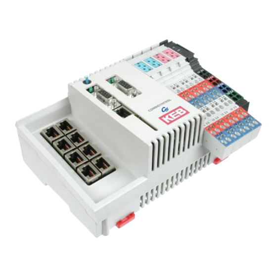
Keb combicontrol c5 ist eine programmierbare steuerung mit direkter anbindung an
bis zu acht keb frequenzumrichter-/ servoachsen der baureihe f5
Inhaltsverzeichnis
Verfügbare Sprachen
Verfügbare Sprachen
Quicklinks
Kapitel
Inhaltsverzeichnis

Verwandte Anleitungen für KEB PCC C5


Inhaltszusammenfassung für KEB PCC C5
- Seite 1 COMBICONTROL Betriebsanleitung PCC C5 Instruction Manual 07/2007...
- Seite 2 The safety and warning reference specified in this manual is not exhaustive. The manual and the information contained in it is made with care. KEB don´t accept a guarantee for misprint or other errors or resulting damages.
-
Seite 3: Inhaltsverzeichnis
Ethernet-Schnittstelle (X6B) ................15 Beschreibung der LED’s ..................15 Multifunktionschalter/-taster S1 .................16 Dateisystem ......................17 Feldbus-Schnittstelle ProfiBus DP ............18 Eckdaten der C5-PROFIBUS-Anschaltung ............18 Die Nutzdaten der KEB-PROFIBUS-DP-Anschaltung ........19 Parameter der PROFIBUS-Anschaltung ............21 Software ....................22 Programmiersystem CoDeSys ................22 Parametriersystem COMBIVIS ................22 Parameterbeschreibung ..................23 6.3.1 Laufzeit- und Fehlerüberwachung .................23... -
Seite 4: Beschreibung Des Gerätes
Verwendungszweck KEB COMBICONTROL C5 ist eine programmierbare Steuerung mit direkter Anbindung an bis zu acht KEB Frequenzumrichter-/ Servoachsen der Baureihe F5. Die Verbindung zu den Achsen ist als HSP5/485 ausgeführt. Mit dieser schnellen, störsicheren Verbindung können alle Achsen mittels eines preiswerten Operators direkt und synchron betrieben werden. Dabei sind Zykluszeiten bis herab zu einer Millisekunde realisierbar. -
Seite 5: Technische Daten
Anschluss an einen Profibus Master, Prozessdatenübertragung, Kommunikations- kanal zur Steuerung und zu den Achsen Achsenschnittstelle HSP5/485 Stecker RJ-45, 8-polig, geschirmt Kabel Cat5, max. 100 m Geschwindigkeit 38,4…250 kBaud Verwendung Anschluss an einen KEB F5 Umrichter/Servo, Prozessdatenübertragung, Kommunikations- kanal D - 5... -
Seite 6: Zubehör
COMBICONTROL Ethernetschnittstelle 09C5xxx-xxxx 19C5xxx-xxxx IEEE 802.3 IEEE802.3 10Base-T 10/100BaseTx Stecker RJ-45, 8-polig, geschirmt Geschwindigkeit 10 MBaud 10/100 MBaud autocrossover Verwendung Verbindung zu CoDeSys (Programmiersystem, Debugging, Visualisierung). Verbindung zu COMBIVIS (Steuerungs- und Achseneinstellung, Scope). Verbindung zu beliebigen Teilnehmern (So- cket-APi). Serielle Schnittstelle 09C5xxx-xxxx 19C5xxx-xxxx DIN66019II, RS232... -
Seite 7: Grundmodul Mit Antriebsschnittstellen
HSP5/485-Schnittstellen zu den Umrichter-/Servoachsen Bis zu acht KEB COMBIVERT F5 können über die Klemmen X1A bis X1H angeschlossen werden. Die Verbindung erfolgt über störsichere RS485-Leitungen, die bis zu 100 m lang sein können. Dabei wird ein geschirmtes Standardkabel mit RJ-45 Stecker auf der Steu- erungsseite und entsprechendem Operator auf dem Umrichter/Servo verwendet. -
Seite 8: Ansicht Der Umrichterschnittstellen X1A
COMBICONTROL %IW32+33 %ID16 1. Wort (32 Bit) von Achse 4 %QD16 1. Wort (32 Bit) zu Achse 4 %IW34 2. Wort (16 Bit) von Achse 4 %QW34 2. Wort (16 Bit) zu Achse 4 %IW35 3. Wort (16 Bit) von Achse 4 %QW35 3. -
Seite 9: Hsp5-Operator Mit Schraubklemme (00F5060-9001)
COMBICONTROL 2.2.3 HSP5-Operator mit Schraubklemme (00F5060-9001) X6E Name Beschreibung TxD- Sendesignal - TxD+ Sendesignal + RxD- Empfangssignal - An der Klemme VCC darf keine RxD+ Empfangssignal + Leitung angeschlossen werden. EnTxD- Handshake Sendesignal - Die hohe Spannung kann die EnTxD+ Handshake Sendesignal + Schnittstelle in der Steuerung EnRxD- Handshake Empfangssignal- zerstören. -
Seite 10: Verbindungskabel Hsp5-Schnittstelle - Operator
COMBICONTROL 2.2.5 Verbindungskabel HSP5-Schnittstelle - Operator Schraubanschluss: Color siehe unten C5 PCC Signal TxD+ TxD- GND RxD+ RxD- GND EnTxD+ EnTxD- X1A…H Operator Signal RxD+ RxD- GND TxD+ TxD- GND EnRxD+ EnRxD- Color siehe unten RJ45 Anschluss: Color siehe unten C5 PCC Signal TxD+ TxD- GND RxD+ RxD- GND EnTxD+ EnTxD- X1A...H... -
Seite 11: Ein-/Ausgangsmodul
COMBICONTROL Ein-/Ausgangsmodul X2A X2B X2C X2D X2U Überlastanzeige der Ausgänge Kontroll-LED’s für Spannung US (Steuerung) Kontroll-LED’s leuchten, wenn Spannung UM (Ein-/Ausgänge) Ein- oder Ausgang gesetzt ist Digitaleingang 5 Digitalausgang 0 Digitaleingang 4 Digitalausgang 1 Digitaleingang 1 Digitalausgang 4 Digitaleingang 0 Digitalausgang 5 + Spannungseingang (US) für Steuerung... -
Seite 12: Spannungsversorgung (X2U)
COMBICONTROL Spannungsversorgung (X2U) Spannungseingang zur Versorgung der Steuerung (US) Spannungseingang zur Versorgung der Ein- und Ausgänge (UM) %IX1.0 Zustand der Versorgungsspannung Ein/Ausgänge (UM) Wird bei Überlastung eines oder mehrerer Ausgänge ge- %IW1 %IX1.1 setzt %IX1.2…%IX1.15 nicht belegt ��� ��� ��� ��� ���... -
Seite 13: Digitale Eingänge (X2A Und X2B)
COMBICONTROL Digitale Eingänge (X2A und X2B) 8 Digitaleingänge 0...7 (2 Blöcke) ��� ��� Zustand der digitalen �� �� %IX0.0…%IX0.7 (%IB1) %IW0 Eingänge 0…7 %IX0.8…%IX0.15 (%IB0) nicht belegt ��� ��� ��� ��� ��� ��� ��� ��� ��� ��� �� �� ��� ��� ���... -
Seite 14: Das Bedienteil
COMBICONTROL Das Bedienteil Name Funktion Zusatz Ansicht Multifunktionsschalter/ Clear -taster Stop LD1 Run-LED grün LD2 Fehler-LED LD3 Ethernet LAN /100 gelb LD4 Ethernet Link / Data grün LD5 Feldbus Data grün LD6 Feldbus Ready grün X6A Serielle Schnittstelle COMBIVIS X6B Ethernet-Schnittstelle COMBIVIS/ CoDeSys X6C Feldbus-Schnittstelle... -
Seite 15: Ethernet-Schnittstelle (X6B)
COMBICONTROL Ethernet-Schnittstelle (X6B) Die standardisierte 10/100 BaseTx Schnittstelle unterstützt die Protokolle TCP/IP und UDP/ Folgende Ports haben dabei diese Funktionen: Der CoDeSys-Port ist standardmäßig auf 1200 eingestellt. Der Port kann über den Parameter Et.03 verändert werden. Hier wird das Steuerungsprogramm mittels CoDeSys verarbeitet (nur TCP/IP möglich). -
Seite 16: Multifunktionschalter/-Taster S1
COMBICONTROL Multifunktionschalter/-taster S1 Der Multifunktionsschalter/-taster ist wie folgt aufgebaut: clear (Taster) stop/reset run (Schalter) Der Taster S1 ist mit folgenden Funktionen belegt: Aktion Funktion Stop --> Run Programm wird gestartet Run --> Stop Programm wird gestoppt, alle Variablen werden zurück- gesetzt (Reset Warm) Stop -->... -
Seite 17: Dateisystem
COMBICONTROL Dateisystem Das Dateisystem besteht aus dem intern eingebauten Flash-Speicher (Laufwerk C:) und einer optional extern steckbaren Speicherkarte (Laufwerk A:). Der Zugriff kann über CoDeSys oder direkt vom Programm der Steuerung erfolgen. Interner Flash-Speicher Dieser Speicher wird als Laufwerk C: angesprochen und kann das Bootprojekt aufnehmen, welches beim Einschalten automatisch geladen und gestartet wird. -
Seite 18: Feldbus-Schnittstelle Profibus Dp
COMBICONTROL Feldbus-Schnittstelle ProfiBus DP Eckdaten der C5-PROFIBUS-Anschaltung Die PROFIBUS-Schnittstelle der C5-Steuerung entspricht dem PROFIBUS-DP-Standard (DIN 19245 Teil 3). Mittlerweile ist der PROFIBUS-DP-Standard auch in einer internationalen Norm, der IEC 61158 als Typ 3 spezifiziert. Die vorliegende Kurzanleitung soll nur die grund- sätzlichen Eigenschaften erläutern. -
Seite 19: Die Nutzdaten Der Keb-Profibus-Dp-Anschaltung
• Prozesseingangsdaten: Daten, die unadressiert vom Slave zum Master gesendet wer- den. Die KEB C5 PROFIBUS-Anschaltung stellt sich flexibel auf die vom Master vorgegebene Konfiguration ein. So ist es z. B. möglich • ausschließlich mit dem Parametrierkanal (8 Byte Nutzdaten) zu arbeiten. Hierfür gibt der Master nur ein Konfigurationsbyte mit dem Wert B7h vor. - Seite 20 �� �� �� �� ��� ��� ��� ��� ��� ��� ��� ��� ��� ��� ��� ��� Die Kodierung der Nutzdaten von der KEB-DP-Anschaltung zum DP-Master Parametrierkanal-Bestätigung Prozesseingangsdaten Legende Low-Byte High-Byte ���� ���������� ���������� High-Word �� ����� �� �� ���� ����...
-
Seite 21: Parameter Der Profibus-Anschaltung
COMBICONTROL Parameter der PROFIBUS-Anschaltung Die Parameter dienen zur Konfiguration der PROFIBUS-Schnittstelle. Adressiert werden die Parameter über PROFIBUS mittels Index (16 Bit) und Subindex (8 Bit). Name Fieldbus Comm Axis Bedeutung Dient zur Umschaltung der PROFIBUS-Kommunikation zwischen den einzelnen Endgeräten, die über die Steuerung adressierbar sind. Index 5FFFh Subindex... -
Seite 22: Software
Die Achssteuerung wird mit dem Programmiersystem CoDeSys der Firma 3S-Software pro- grammiert (www.3s-software.com). Diese Programmiersoftware ist frei im Internet erhältlich. Als Zubehör ist ein Target Information File (TNF) von KEB für die Steuerung verfügbar, das alle nötigen Hardwarefestlegungen enthält. Weiterhin enthalten ist eine Bibliothek mit Firm- ware-Funktionsbausteinen zum Zugriff auf die Peripherie (Achsen, Echtzeituhr, Schalter, LEDs , Dateisystem). -
Seite 23: Parameterbeschreibung
COMBICONTROL Parameterbeschreibung 6.3.1 Laufzeit- und Fehlerüberwachung Die ru-Parameter dienen zur Überwachnung des Programablaufes. ru.00 Status Adresse 0200h Progammstatus no prog kein Progamm geladen prog OK Programm geladen prog corrupt Programm-Checksummenfehler Steuerungsstatus Programm läuft stop Programm gestoppt breakpoint Programm steht auf Überwachungspunkt Fehlerstatus err_cyctime Die eingestellte Zykluszeit wurde überschritten... -
Seite 24: Ethernetparameter
COMBICONTROL 6.3.2 Ethernetparameter Die folgenden Parameter enthalten die Werte, die zur Kommunikation über die Ethernet- Schnittstelle benötigt werden. et.00 MAC Adresse Adresse 0300h Die MAC-Adresse (Media Access Control) wird aus 6 Byte gebildet. Die ersten drei Bytes enthalten den Herstellercode (00-08-FA). Angezeigt werden hier nur die untersten 4 Bytes „FAxxxxxx“. -
Seite 25: Gateway Adresse
COMBICONTROL Datenport Passwort et.09 Adresse 0309h Dieser Parameter legt das Schreibschutzpasswort für den COMBIVIS Datenport fest. Die Programmierung des Passwortes erfolgt nur über die serielle Schnittstelle, dann ist für einen Schreibzugriff über den Datenport hier dieses Passwortes erneut einzugeben. Bei gesperrtem Datenportschreibzugriff wird die Fehlermeldung „Operation nicht möglich“... -
Seite 26: Prozessabbild
COMBICONTROL Sekunden rc.01 Adresse 0401h Dieser Parameter zeigt die Sekunden im Bereich von 0...59 an. Schreiben auf diesen Parmeter stellt die Sekunden ein. Datum rc.02 Adresse 0402h Dieser Parameter zeigt das Datum im Format TT-MM an. Schreiben auf diesen Parmeter stellt das Datum ein. -
Seite 27: Bedienoberfläche
COMBICONTROL pi.06 Achs-Eingangsdaten 3 Adresse 0506h Zeigt den Wert des 3.Prozess-Eingangsdatums (16 Bit) der Achsen an. Satz 0 ist für die Daten der Achse 1, Satz 1 für die Achse 2, etc. pi.07 Achs-Ausgangsdaten 3 Adresse 0507h Zeigt den Wert des 3.Prozess-Ausgangsdatums (16 Bit) der Achsen an. Satz 0 ist für die Daten der Achse 1, Satz 1 für die Achse 2, etc. -
Seite 28: Systemparameter
COMBICONTROL ud.05 Rx-Fehlerzähler Adresse 0805h Dieser Parameter zählt die Empfangsfehler bei der Kommunikation mit den Achsen. Da- bei zeigt Satz 0 die Fehler der Achse 1, Satz 1 die der Achse 2 usw. an. ud.06 Tx-Fehlerzähler Adresse 0806h Dieser Parameter zählt die Fehler beim Senden zu den einzelnen Achsen. Dabei zeigt Satz 0 die Fehler der Achse 1, Satz 1 die der Achse 2 usw. -
Seite 29: Debugging
Dieser Parameter legt die Feldbus-Geräteadresse fest. sy.07 Baudrate 66019II Adresse 0007h Mit diesem Parameter wird die Baudrate für das KEB DIN 66019II Protokoll eingestellt. sy.10 Adresse 000Ah Anzeige des Gerätetyps. Die folgenden Parameter dienen zum Betrieb des Inverter-Scope-Teils von COMBIVIS. -
Seite 30: Systemvariablen
COMBICONTROL Systemvariablen Folgende Systemvariablen sind im SPS-Programm verfügbar: SYSAXISMODE Zeigt die über den Funktionsbaustein ‚tSetModes‘ eingestellte Achsenbetriebsarten an. SYSERRORAXIS Zeigt die ausgefallenen überwachten oder zyklisch/synchron betriebenen Achsen an. Bei Ausfall einer Achse wird die rote Fehler-LED am Bedienteil eingeschaltet und der Event „excpt_axis_error“... - Seite 31 COMBICONTROL D - 31...
- Seite 60 COMBICONTROL GB - 31...
- Seite 61 • mail: www.keb.de info@keb.de KEB (UK) Ltd. KEB Antriebstechnik GmbH & Co. KG 6 Chieftain Buisiness Park, Morris Close Wildbacher Str. 5 • D–08289 Schneeberg Park Farm, Wellingborough GB-Northants, NN8 6 XF fon: +49 3772 67-0 • fax: +49 3772 67-281 fon: +44 1933 402220 •...