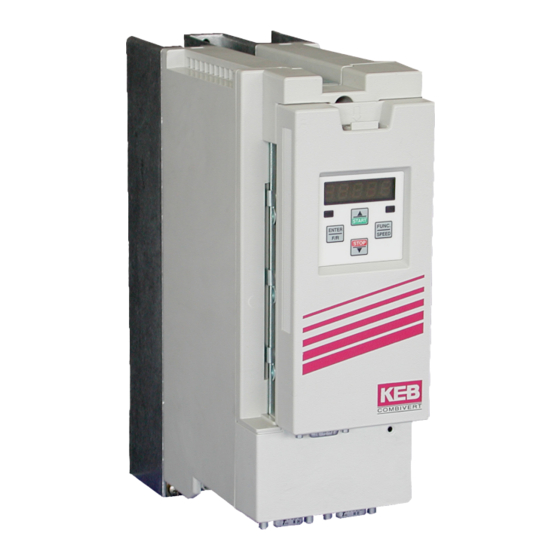
KEB COMBIVERT F5 Installationsanleitung
B-gehäuse
Vorschau ausblenden
Andere Handbücher für COMBIVERT F5:
- Betriebsanleitung (164 Seiten) ,
- Gebrauchsanleitung (104 Seiten) ,
- Installationsanleitung (92 Seiten)
Inhaltsverzeichnis
Verfügbare Sprachen
Verfügbare Sprachen
Quicklinks
Kapitel
Inhaltsverzeichnis

Verwandte Anleitungen für KEB COMBIVERT F5


Inhaltszusammenfassung für KEB COMBIVERT F5
- Seite 1 C O M B I V E R T Installationsanleitung B-Gehäuse Installation Guideline B-Housing 11/2004...
- Seite 2 Seite 3 ....30 Page 31 ..... 58...
- Seite 4 Diese Anleitung beschreibt den KEB COMBIVERT F5. Im Einzelnen wird auf den Einbau, die Anschlussmöglichkeiten sowie die grundlegende Bedienung eingegangen. Aufgrund der vielfältigen Einsatz- und Programmiermöglichkeiten ist der anwendungsspezifische Anschluss- bzw. Verdrahtungsplan, die Parametereinstellung sowie Hinweise zur Inbe- triebnahme der Dokumentation des Maschinenherstellers zu entnehmen.
-
Seite 5: Inhaltsverzeichnis
Inhaltsverzeichnis Sicherheits- und Anwendunghinweise ............6 Produktbeschreibung ..................7 Verwendungszweck ......................7 Geräteidentifikation ......................7 Technische Daten ......................8 2.3.1 230 V-Klasse ........................8 2.3.2 400 V-Klasse ........................9 Abmessungen und Anschlüsse ................... 10 Einbau und Anschluss .................. 11 Schaltschrankeinbau ..................... 11 EMV-gerechte Verdrahtung ................... -
Seite 6: Wichtig, Unbedingt Lesen
Wichtig, unbedingt lesen Sicherheits- und Anwendunghinweise Sicherheits- und Anwendungshinweise für Antriebsstromrichter (gemäß: Niederspannungsrichtlinie 73/23/EWG) 1. Allgemein 4. Aufstellung Während des Betriebes können Antriebsstromrichter ihrer Die Aufstellung und Kühlung der Geräte muß entsprechend Schutzart entsprechend spannungsführende, blanke, den Vorschriften der zugehörigen Dokumentation erfolgen. gegebenenfalls auch bewegliche oder rotierende Teile, Die Antriebsstromrichter sind vor unzulässiger Beanspru- sowie heiße Oberflächen besitzen. -
Seite 7: Produktbeschreibung
Produktbeschreibung Produktbeschreibung Verwendungszweck Der Frequenzumrichter KEB COMBIVERT F5 dient ausschließlich zur Steuerung und Regelung von Asynchronmotoren. Der Betrieb anderer elektrischer Verbraucher ist unter- sagt und kann zur Zerstörung der Geräte führen. Frequenzumrichter sind Komponenten, die zum Einbau in elektrische Anlagen oder Ma- schinen bestimmt sind. -
Seite 8: Technische Daten
Produktbeschreibung Technische Daten 2.3.1 230 V-Klasse Gerätegröße Gehäusegröße Netzphasen Ausgangsbemessungsleistung [kVA] Max. Motorbemessungsleistung [kW] 0,37 0,75 Ausgangsbemessungsstrom Max. Kurzzeitgrenzstrom 12,6 OC-Auslösestrom 15,1 21,6 Eingangsbemessungsstrom [A] 4,6 14 9,8 20 14 Max. zulässige Netzsicherung (träge) 16 25 20 Bemessungsschaltfrequenz [kHz] Max. Schaltfrequenz [kHz] Verlustleistung bei Bemessungsbetrieb Min. -
Seite 9: 400 V-Klasse
Produktbeschreibung 2.3.2 400 V-Klasse Gerätegröße Gehäusegröße Netzphasen Ausgangsbemessungsleistung [kVA] 0,9 Max. Motorbemessungsleistung [kW] 0,37 0,75 Ausgangsbemessungsstrom [A] 1,3 Max. Kurzzeitgrenzstrom [A] 2,3 10,4 17 OC-Auslösestrom [A] 2,8 12,5 21 Eingangsbemessungsstrom [A] 1,8 Max. zulässige Netzsicherung (träge) [A] 16 Bemessungsschaltfrequenz [kHz] 16 Max. -
Seite 10: Abmessungen Und Anschlüsse
Produktbeschreibung Abmessungen und Anschlüsse * mit Operator Anschluss für Netzversorgung, Motor, Bremswiderstand und Temperaturerfassung Anschluss für Steuerleitungen Anschluss für Operator oder HSP5-Servicekabel Anschluss Abschirmung / Schutzleiter Eingangsspannung beachten, da 230V(1/3-phasig) und 400V-Klasse (3-phasig) möglich! -
Seite 11: Einbau Und Anschluss
• Alle Leitungen möglichst dicht an der Montageplatte verlegen - ideal im Metallkabelkanal. • COMBIVERT gut leitend mit der Montageplatte montieren. Lack vorher entfernen. Weitere Hinweise zur EMV - gerech- ten Verdrahtung finden Sie bei KEB im Internet. -
Seite 12: Anschluss Des Leistungsteil
• T1, T2 Temperatursensor / -schalter (siehe Kapitel 3.3.6) 3.3.2 Verdrahtungshinweise Achten Sie unbedingt auf die Anschlussspannung des KEB COMBIVERT. Ein 230 V-Gerät am 400 V-Netz wird sofort zerstört. Vertauschen Sie niemals die Netz- und Motorleitung. In einigen Ländern wird gefordert, dass die PE-Klemme direkt im Klemmkasten... -
Seite 13: Netzanschluss
Einbau und Anschluss 3.3.3 Netzanschluss Netzanschluss 230 V 3-phasig Netzanschluss 230 V 1-phasig 1 x 180...260 V AC 3 x 180...260 V AC N/L2 N/L2 Absicherung Netzanschluss 400 V 3-phasig • Sicherung (siehe Kapitel 2.3) oder 3 x 305...500 V AC •... -
Seite 14: Motoranschluss
Einbau und Anschluss 3.3.4 Motoranschluss • max. Motorleitungslänge siehe Kapitel 2.3 N/L2 Abschirmungen großflächig auf der Montageplatte und am Motorgehäuse auflegen Motor-PTC (optional) 3.3.5 Anschluss der Temperaturerfassung • Klemmen T1, T2 • Ansprechwiderstand 1,65...4 kOhm • Rückstellwiderstand 0,75...1,65 kOhm • Ausführung gem. -
Seite 15: Anschluss Eines Bremswiderstandes Mit Temperaturüberwachung
Einbau und Anschluss 3.3.6 Anschluss eines Bremswiderstandes mit Temperaturüberwachung • ++, PB Anschluss Bremswiderstand • technische Daten (siehe Kapitel 2.3) • bei Auslösung der Temperaturüberwachung wird die Eingangsspannung weggeschaltet • für zusätzlichen Schutz bei generatorischem Betrieb die Hilfskontakte 11 und 12 vom Netzschütz K1 anschließen (siehe 3.3.5) N/L2 230 oder 24 V AC/DC... -
Seite 16: Steuerkarte Basic
Einbau und Anschluss Steuerkarte Basic 3.4.1 X2A Steuerklemmleiste • Anzugsmoment 0,22...0,25 Nm • Abgeschirmte/verdrillte Leitungen verwenden 1 5 7 8 10 11 14 15 16 20 22 24 25 26 27 28 29 • Schirm einseitig am Umrichter auf Erdpotential legen PIN Funktion Nam e Erklärung... -
Seite 17: Anschluss Der Steuerklemmleiste
Einbau und Anschluss 3.4.2 Anschluss der Steuerklemmleiste Sollwertsignal Stromsignal Sollwertpotentiometer 0...±10 V DC 0...20 mA 3...10 kOhm 4...20 mA Analogausgang ±10 V DC / max.5 mA nicht bei A- und B-Gehäusen max. 30 V / 0,01...1 A DC max. 30 V / 0,01...1 A DC Um Störungen zu vermeiden ist für analoge und digitale Steuerleitungen ein getrennter Schirm vorzusehen. -
Seite 18: Steuerkarte Compact/General
AN1+ Differenzspannungseingänge; 0...±10 VDC; Ri = 55kOhm 2 - Sollw erteingang 1 AN1- AN1: Vorgabe des analogen Sollw ertes 3 + Analogeingang 2 AN2+ AN2: bei KEB Werkseinstellung keine Funktion 4 - Analogeingang 2 AN2- Progr. Analogausgänge 0...±10 VDC/max. 5 mA; w ird vom Maschinenbauer festgelegt 5 Analogausgang 1 Ausgabe der Ausgangsfrequenz 0...±100 Hz... -
Seite 19: Anschluss Der Steuerklemmleiste
Einbau und Anschluss 3.5.2 Anschluss der Steuerklemmleiste Stromsignal Sollwertpotentiometer Sollwertsignal 0...20 mA 3...10 kOhm 0...±10 V DC 4...20 mA Analogausgang ±10 V DC / max. 5 mA max. 30 V DC / 0,01...1 A max. 30 V DC / 0,01...1 A Um Störungen zu vermeiden ist für analoge und digitale Steuerleitungen ein getrennter Schirm vorzusehen. -
Seite 20: Bedienzubehör
Standardkabels würde die PC-Schnittstelle zerstören. 4.1.2 Digitaloperator (Artikelnummer 00.F5.060-1000) Als Zubehör zur lokalen Bedienung des KEB COMBIVERT F5 ist ein Operator erhältlich. Um Fehlfunktionen zu vermeiden, muss der Umrichter vor dem Aufstecken / Abziehen des Operators in den Status noP (Reglerfreigabe öffnen) gebracht werden. Bei der Inbe- triebnahme des Umrichters wird immer mit den zuletzt abgespeicherten Werten, bzw. -
Seite 21: Fernbedienung (Hsp5-Verlängerung)
Operatoren für spezielle Einsatzfälle (Profibus, Interbus, Sercos, CAN) bestückt werden. Weitere Informationen hierzu finden Sie auf unserer Homepage. Tastaturbedienung 4.2.1 Parameternummern und /-werte Beim Einschalten des KEB COMBIVERT F5 erscheint der Wert des Parameters CP.1. Mit der Funktionstaste wird zwischen FUNC. Parameterwert und Parameternummer SPEED gewechselt. -
Seite 22: Rücksetzen Von Fehlermeldungen
Durch ENTER wird nur die Fehlermeldung in der Anzeige zurückgesetzt. Um den Fehler selbst zurückzusetzen, muß erst die Ursache behoben werden und ein Reset oder ein Kaltstart erfolgen. 4.2.3 Passworteingabe Der KEB COMBIVERT ist mit einem umfassenden Passwortschutz ausgestattet. Abhän- gig vom eingegebenen Passwort sind folgende Modis möglich: Anzeige Modus CP_ro Endkundenmenü... -
Seite 23: Parameterbeschreibung
CP-Parameter Parameterbeschreibung Ein- ↵ Param eter Einstellbereich Auf- lösung fault heit sprung CP.0 Passworteingabe 0...9999 ud.1 CP.1 Istfrequenzanzeige -400...400 0,0125 ru.3 CP.2 Sollfrequenzanzeige -400...400 0,0125 ru.1 CP.3 Umrichter Status 0...255 ru.0 CP.4 Scheinstrom 0...6553,5 ru.15 CP.5 Scheinstrom / Spitzenwert 0...6553,5 ru.16 CP.6 Auslastung... - Seite 24 „Reverse Constant“ Antrieb läuft mit konstanter Drehzahl und Drehrichtung Rückwärts. Informationen über Statusmeldungen sowie die Ursache und Beseitigung von Fehler- meldungen finden Sie unter www.keb.de ==>Dokumentation ==> Bedienungsanleitungen ==> Sonstiges ==> Serviceinformationen ==> Fehler- und Statusmeldungen.doc . CP.17 Spannungsstabilisierung Mit diesem Parameter kann eine geregelte Ausgangsspannung, bezogen auf die Eck- frequenz, eingestellt werden.
- Seite 25 CP-Parameter CP.22 DC-Bremsung / Modus Bei der DC-Bremsung wird der Motor nicht über die Rampe verzögert. Das schnelle Abbremsen erfolgt durch eine Gleichspannung, die auf die Motorwicklung gegeben wird. Dieser Parameter legt fest, wie die DC-Bremsung ausgelöst wird. Wert Aktivierung DC-Bremsung abgeschaltet.
-
Seite 26: Cp.28 Reaktion Auf Externe Übertemperatur
CP-Parameter CP.28 Reaktion auf externe Übertemperatur CP.28 bestimmt die Reaktion des Antriebes auf die externe Temperaturüberwachung. Bei der Werkseinstellung ist die Funktion abgeschaltet. Um die Funktion zu aktivie- ren, müssen die Leistungsteilklemmen T1/T2 angeschlossen werden. Dann kann die Reaktion entsprechend folgender Tabelle eingestellt werden. Liegt die Übertemperatur nicht mehr an, wird die Meldung E.ndOH (bzw. - Seite 27 CP.31 Relaisausgang 1 / Funktion (Kl. X2A.24...26) CP.32 Relaisausgang 2 / Funktion (Kl. X2A.27...29) Der Schaltlevel für CP.31 ist auf 100,00 voreingestellt. Der Schaltlevel für CP.32 wird mit CP.33 eingestellt! Wert Funktion Keine Funktion (generell aus) Generell an Run-Signal; auch bei DC-Bremse Betriebsbereit-Signal (kein Fehler) Störmelderelais Störmelderelais (ohne Auto-Reset)
- Seite 28 CP.34 Drehrichtungsquelle Mit diesem Parameter wird die Quelle und die Art der Auswertung für die Drehrichtungs- vorgabe festgelegt (Enter-Parameter). Mit CP.34 ändert man nicht die Drehrichtungs- quelle der Festfrequenzen (CP.19...21). Wert Drehrichtung 0/1 Nur Applikationsmode Vorgabe über Klemmleiste Vorwärts/Rückwärts; negative Sollwerte werden zu Null gesetzt (Werkseinstellung).
-
Seite 29: Zertifizierungen
Markt sind folgende zusätzli- che Hinweise unbedingt zu beachten: • Der KEB COMBIVERT ist für einen Einsatz am Netz mit einem max. Kurzschlussstrom von = 10 kA (symmetrisch) bei max. 240 V AC, bzw. 480 V AC zu verwenden •... -
Seite 30: Weitere Anleitungen
Weitere Anleitungen Weitere Anleitungen Ergänzende Anleitungen und Hinweise zum Download finden Sie unter www.keb.de > Dokumentation > Betriebsanleitungen Allgemeine Anleitungen • Teil 1 EMV- und Sicherheitshinweise Gerätespezifische Anleitungen • Teil 2 Leistungsteile • Teil 3 Steuerteil Servicehinweise • Download von Parameterlisten •... - Seite 60 Karl E. Brinkmann GmbH Försterweg 36-38 • D-32683 Barntrup fon: +49 5263 401-0 • fax: +49 5263 401-116 net: www.keb.de • mail: info@keb.de KEB Antriebstechnik GmbH & Co. KG KEB - YAMAKYU Ltd. Wildbacher Str. 5 • D–08289 Schneeberg 15–16, 2–Chome, Takanawa Minato-ku fon: +49 3772 67-0 •...