Herunterladen Inhalt Inhalt Diese Seite drucken
Reely Speedy Bedienungsanleitung

Reely Speedy Bedienungsanleitung

Elektro-segelflugmodell pnp
Vorschau ausblenden Andere Handbücher für Speedy:
Inhaltsverzeichnis

Werbung

Verfügbare Sprachen

Verfügbare Sprachen

Bedienungsanleitung
Elektro-Segelflugmodell „Speedy" PNP
Best.-Nr. 1558370
Seite 2 - 27
Operating Instructions
Electrical Glider Model "Speedy" PNP
Item No. 1558370
Page 28 - 53

Werbung

Kapitel

Inhaltsverzeichnis
loading

Inhaltszusammenfassung für Reely Speedy

  • Seite 1 Bedienungsanleitung Elektro-Segelflugmodell „Speedy“ PNP Best.-Nr. 1558370 Seite 2 - 27 Operating Instructions Electrical Glider Model “Speedy” PNP Item No. 1558370 Page 28 - 53...
  • Seite 2: Inhaltsverzeichnis

    Inhaltsverzeichnis Seite Einführung ................................4 Symbol-Erklärung ..............................4 Bestimmungsgemäße Verwendung ........................5 Produktbeschreibung ............................5 Lieferumfang ................................6 Sicherheitshinweise .............................7 a) Allgemein ...............................7 b) Vor der Inbetriebnahme ..........................8 c) Während des Betriebs ...........................8 Allgemeine Batterie- und Akku-Hinweise ......................9 Fertigstellen des Flugmodells ..........................10 a) Abnehmen der Kabinenhaube ........................10 b) Montage des Höhenleitwerks ........................
  • Seite 3 Seite 11. Nachrüsten der Landeklappen ...........................23 12. Wartung und Pflege ............................25 13. Entsorgung ................................25 a) Produkt ................................25 b) Batterien/Akkus ............................25 14. Beheben von Störungen ............................26 15. Technische Daten ..............................27 a) Flugmodell ..............................27 b) Flugregler ..............................27...
  • Seite 4: Einführung

    1. Einführung Sehr geehrte Kundin, sehr geehrter Kunde, wir bedanken uns für den Kauf dieses Produkts. Dieses Produkt entspricht den gesetzlichen, nationalen und europäischen Anforderungen. Um diesen Zustand zu erhalten und einen gefahrlosen Betrieb sicherzustellen, müssen Sie als Anwender diese Bedienungsanleitung beachten! Diese Bedienungsanleitung gehört zu diesem Produkt.
  • Seite 5: Bestimmungsgemäße Verwendung

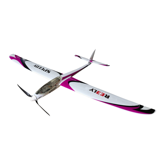
    Sie allein sind für den gefahrlosen Betrieb des Modells verantwortlich! 4. Produktbeschreibung Bei dem Flugmodell „Speedy“ handelt es sich um ein vorgefertigtes PNP-Modell (Plug ´n Play), das mit wenigen Handgriffen einsatzbereit ist. Der Rumpf, die Tragflächen und die Leitwerke aus verstärktem Formschaumstoff (EPO) sind bereits vormontiert.
  • Seite 6: Lieferumfang

    5. Lieferumfang Bild 1 1 Höhenruderhälften 2 Rumpf 3 Tragflächenschraube 4 Tragflächen-Verbinder 5 Höhenleitwerk-Verbinder 6 Höhenleitwerk-Führungsstift 7 V-Kabel 8 Tragflächenhälften 9 Klettverschluss Aus fototechnischen Gründen ist die mitgelieferte Bedienungsanleitung nicht abgebildet. Aktuelle Bedienungsanleitungen Laden Sie aktuelle Bedienungsanleitungen über den Link www.conrad.com/downloads herunter oder scannen Sie den abgebildeten QR-Code.
  • Seite 7: Sicherheitshinweise

    6. Sicherheitshinweise Bei Schäden, die durch Nichtbeachtung dieser Bedienungsanleitung verursacht werden, erlischt die Gewährleistung/Garantie. Für Folgeschäden übernehmen wir keine Haftung! Bei Sach- oder Personenschäden, die durch unsachgemäße Handhabung oder Nichtbeachten der Sicherheitshinweise verursacht werden, übernehmen wir keine Haftung! In solchen Fällen erlischt die Gewährleistung/Garantie.
  • Seite 8: B) Vor Der Inbetriebnahme

    b) Vor der Inbetriebnahme • Überprüfen Sie die Funktionssicherheit Ihres Modells und der Fernsteueranlage. Achten Sie dabei auf sichtbare Beschädigungen, wie z.B. defekte Steckverbindungen oder beschädigte Kabel. Sämtliche be- weglichen Teile am Modell müssen leichtgängig funktionieren, dürfen jedoch kein Spiel in der Lagerung aufweisen.
  • Seite 9: Allgemeine Batterie- Und Akku-Hinweise

    7. Allgemeine Batterie- und Akku-Hinweise Obwohl der Umgang mit Batterien und Akkus im täglichen Leben heute eine Selbstverständlichkeit ist, bestehen zahlreiche Gefahren und Probleme. Beachten Sie deshalb unbedingt die nachfolgend genannten allgemeinen Informationen und Sicherheitshinweise zum Umgang mit Batterien und Akkus. • Batterien/Akkus gehören nicht in Kinderhände.
  • Seite 10: Fertigstellen Des Flugmodells

    8. Fertigstellen des Flugmodells Im weiteren Verlauf der Anleitung beziehen sich die Ziffern im Text immer auf das nebenstehende Bild bzw. auf die Bilder innerhalb des Abschnittes. Querverweise zu anderen Bildern werden mit der entsprechenden Bildnummer angegeben. Das in der Anleitung gezeigte Modell dient lediglich zu Anschauungszwecken. Farbgebung und Design des serienmäßig gelieferten Modells können von dem in der Anleitung gezeigten Modell abweichen.
  • Seite 11: Montage Des Höhenleitwerks

    b) Montage des Höhenleitwerks Setzen Sie den Höhenleitwerk-Verbinder (1) sowie den Höhenleitwerk-Führungsstift (2) in eine der beiden Leit- werkshälften (3) ein. Schieben Sie eine der beiden Distanzscheiben (4) auf den Höhenleitwerk-Verbinder. Setzen Sie die Einheit dann so in das Seitenleitwerk ein, dass der Höhenleitwerk-Führungsstift durch die Bohrung der Höhenruder-Anlenkung (5) geschoben wird.
  • Seite 12: Montage Der Tragflächen

    c) Montage der Tragflächen Schieben Sie zunächst den vierkantigen Tragflächen- Verbinder (1) in die rechte Tragfläche. Schieben Sie danach den Verbinder durch den Rumpf und fädeln dabei den Anschlussstecker der Querruder-Servos (2) durch die vorgesehene Öffnung. Nachdem Sie die linke Tragfläche nach demselben Sche- ma montiert haben, werden beide Tragflächenhälften bis zum Anschlag zusammengeschoben und von der Rumpf- unterseite mit der Tragflächenschraube (4) gesichert.
  • Seite 13: Einbau Und Anschließen Des Empfängers

    e) Einbau und Anschließen des Empfängers Sollte der Empfänger nur 4 Kanäle zur Verfügung stellen, sind die beiden Querruder-Servos mit Hilfe des beiliegen- den V-Kabels an einem gemeinsamen Empfängeraus- gang anzuschließen. Sollte der Empfänger mehr als 4 Kanäle zur Verfügung stellen, so ist es empfehlenswert, jedes Querruder-Servo an einem separaten Ausgang anzuschließen.
  • Seite 14: Einsetzen Des Flugakkus

    g) Einsetzen des Flugakkus Der Flugakku (1) wird entsprechend der nebenstehenden Abbildung eingesetzt. Wichtig! Die Akkuseite mit den Anschlusskabeln (2) muss dabei in Flugrichtung nach hinten zeigen, damit keine Kabelschlaufe entsteht, die u.U. am Motor schleifen kann. Die genaue Position des Akkus ergibt sich bei der Über- prüfung des Schwerpunktes, siehe Kapitel 8.
  • Seite 15: Einstellen Der Ruderausschläge

    i) Einstellen der Ruderausschläge Einstellen der Neutralstellung Nehmen Sie den Sender in Betrieb und stellen Sie die Trimmwerte für alle Steuerkanäle auf die Mittelstellung. Schließen Sie danach den Flugakku am Flugregler an. Die Endkanten der Querruder müssen im Außenbereich bündig mit der Hinterkante der Tragflächen abschließen. Das Seitenruder muss dem Profilverlauf des Seitenleit- werks folgen.
  • Seite 16: Überprüfen Des Schwerpunktes

    Tipp aus der Praxis: Falls die verwendete Fernsteuerung es zulässt, empfehlen wir große und per umschaltbarer Wegbegrenzung (Dual Rate-Funktion) verkleinerte Ruderausschläge einzustellen. Bei den großen Ruderausschlägen ist es ratsam, die Ex- ponentialfunktion zu nutzen. Die nachfolgende Tabelle dient als Anhaltspunkt für die Ruderausschläge, wobei die tatsächlichen Wege nach den persönlichen Vorlieben des Piloten erflogen werden müssen.
  • Seite 17: Überprüfen Der Motorfunktion

    k) Überprüfen der Motorfunktion Achtung! Vergewissern Sie sich, dass bei diesem Motortest keine losen Teile wie Papier, Folien oder sonstige Ge- genstände von der Luftschraube angesaugt werden können. Achten Sie ebenfalls darauf, dass das Modell bei diesem Test sicher gehalten wird und sich keine Körperteile im Dreh- und Gefahrenbereich des Propel- lers befinden.
  • Seite 18: Programmieren Des Flugreglers

    9. Programmieren des Flugreglers Der eingebaute Flugregler ist bereits an Werk programmiert. Dabei wurden folgende Werte eingespeichert: Bremsfunktion: Eingeschaltet Akku-Typ: LiPo Motor-Abschaltung: Sanft Abschalt-Spannung: Mittel (3,15 V/Zelle) Motor-Anlaufverhalten: Normal (300 ms) Motor-Timing: Niedrig (3,75°) Im Störungsfall oder beim Einsatz des Flugreglers in einem anderen Modell kann es erforderlich werden, das Pro- grammiermenü...
  • Seite 19 Je nach aufgerufenem Menüpunkt gibt der Flugregler nun 1, 2 oder 3 kurze Signaltöne ( - , - - , - - - ) ab. Die Zuord- nung der Signaltöne kann der nachfolgenden Tabelle entnommen werden. Funktion 1x kurzer Ton 2x kurze Töne 3x kurze Töne Bremse...
  • Seite 20: Einfliegen Des Modells

    10. Einfliegen des Modells Nachdem Sie den Schwerpunkt, die Funktion des Motors sowie die Richtung der Ruderausschläge überprüft haben, ist Ihr Modell zum Erstflug bereit. Wir empfehlen Ihnen, in jedem Fall einen erfahrenen Modellflug-Piloten zu kontaktie- ren oder einen Modellbau-Verein in Ihrer Nähe aufzusuchen, falls Sie mit dem korrekten Einfliegen eines Flugmodells nicht vertraut sind. Falls Ihre Fernsteuerung über einen Timer verfügt, so stellen Sie diesen auf 3 Minuten ein. Nach der Landung prüfen Sie die Restkapazität des Akkus und korrigieren bei Bedarf die Timerzeit nach oben oder unten.
  • Seite 21: Überprüfen Der Schwerpunktlage

    d) Überprüfen der Schwerpunktlage Lassen Sie das Modell auf Sicherheitshöhe aufsteigen und schalten danach den Motor ab. Fliegen Sie im 90°-Winkel zur Blickrichtung und drücken das Modell in einen ca. 30°-Winkel gegen den Wind nach unten. Wenn das Modell Fahrt aufgenommen hat, führen Sie den Steuerknüppel für das Höhenruder zurück in die Mittelstellung und beobach- ten das Flugverhalten des Modells.
  • Seite 22: Korrektur Von Motorsturz Und Motorseitenzug

    g) Korrektur von Motorsturz und Motorseitenzug Bei weiteren Flügen werden der Motorsturz und der Motorseitenzug überprüft. Wenn das Modell bei voller Motor- leistung aus der horizontalen Fluglage zu steil nach oben zieht, muss der Motorsturz (Neigung der Motorwelle nach unten) vergrößert werden. Zieht das Modell im Steigflug stark nach links, muss der Motorseitenzug (Neigung der Motorwelle nach rechts) ver- größert werden.
  • Seite 23: Nachrüsten Der Landeklappen

    11. Nachrüsten der Landeklappen Erfahrene Modellbauer haben die Möglichkeit, Landeklappen im Modell nachzurüsten. Normalerweise ist dies nicht erforderlich, aber im Modell sind die Vorbereitungen für einen Landklappeneinbau bereits ab Werk durchgeführt und der Umbau ist verhältnismäßig leicht durchführbar. Allerdings ist dann eine Fernsteuerung mit mehr als vier Kanälen erforderlich.
  • Seite 24 Bild 16...
  • Seite 25: Wartung Und Pflege

    12. Wartung und Pflege Überprüfen Sie in regelmäßigen Abständen die Funktionssicherheit des Modells sowie die Leichtgängigkeit des Mo- tors. Äußerlich dürfen das Modell nur mit einem weichen, trockenen Tuch oder Pinsel gereinigt werden. Verwenden Sie auf keinen Fall aggressive Reinigungsmittel oder chemische Lösungen, da sonst die Oberflächen beschädigt werden können. Wichtig! Sollten Sie beschädigte oder verschlissene Teile erneuern müssen, so setzen Sie nur Original-Ersatzteile ein. Die Ersatzteilliste finden Sie auf unserer Internetseite www.conrad.com im Download-Bereich zum jeweiligen Produkt.
  • Seite 26: Beheben Von Störungen

    14. Beheben von Störungen Auch wenn das Modell und die Fernsteueranlage nach dem heutigen Stand der Technik gebaut wurden, kann es den- noch zu Fehlfunktionen oder Störungen kommen. Aus diesem Grund möchten wir Ihnen aufzeigen, wie Sie eventuelle Störungen beseitigen können. Problem Abhilfe Der Motor dreht sich nicht und gibt beim...
  • Seite 27: Technische Daten

    15. Technische Daten a) Flugmodell Flügelspannweite ..........1525 mm Rumpflänge ............1080 mm Flächeninhalt ............ 23,5 dm² Gewicht (ohne Flugakku) ........980 g Fernsteuerung ..........4 bis 6 Kanäle Motor ..............950 kV Klapp-Propeller ..........34,29 cm x 17,78 cm (13,5“ x 7“) Erforderlicher Flugakku ........
  • Seite 28 Table of Contents Page Introduction ................................30 Explanation of Symbols .............................30 Intended Use ..............................31 Product Description ............................31 Scope of Delivery ...............................32 Safety Notes ..............................33 a) General Information .............................33 b) Before Commissioning ..........................34 c) During Operation ............................34 Notes on Batteries and Rechargeable Batteries ....................35 Final Assembly of the model airplane ........................36 a) Removing the Canopy ..........................36 b) Mounting the Elevator Unit ..........................37...
  • Seite 29 Page 11. Retrofitting the Landing Flaps ..........................49 12. Maintenance and Care ............................51 13. Disposal ................................51 a) Product ................................51 b) Batteries/Rechargeable Batteries ........................51 14. Troubleshooting ..............................52 15. Technical Data ..............................53 a) Flight Model ..............................53 b) Flight controller ............................53...
  • Seite 30: Introduction

    1. Introduction Dear Customer, thank you for purchasing this product. This product complies with the statutory national and European requirements. To maintain this status and to ensure safe operation, you as the user must observe these operating instructions! These operating instructions are part of this product. They contain important notes on commissioning and handling.
  • Seite 31: Intended Use

    You are solely responsible for safe operation of the model! 4. Product Description The flight model "Speedy" is a pre-fabricated PNP model (Plug'n'Play), that is ready for use with just a few steps. The fuselage, wings and tail unit are made of reinforced moulded foam (EPO) and are pre-assembled. All drive and control components are built-in and ready for use. The colour design is applied with a coloured decal sheet, which is applied ex works.
  • Seite 32: Scope Of Delivery

    5. Scope of Delivery Figure 1 1 Elevator halves 2 Fuselage 3 Wing screw 4 Wing connector 5 Elevator unit connector 6 Elevator unit guide pin 7 V-cable 8 Wing halves 9 Hook and loop closure For photo-technical reasons, the enclosed operating instructions are not illustrated. Current operating instructions Download the current operating instructions via the link www.conrad.com/downloads or scan the displayed QR code.
  • Seite 33: Safety Notes

    6. Safety Notes In case of damage caused by non-compliance with these operating instructions, the warranty/ guarantee will expire. We do not assume any liability for consequential damage! We do not assume any liability for property damage or personal injury caused by improper use or non-compliance with the safety instructions! In such cases the warranty/guarantee is voided.
  • Seite 34: Before Commissioning

    b) Before Commissioning • Check the functional reliability of your model and of the remote control system. Watch out for any visible damage such as defective plug connections or damaged cables. All moving parts on the model must run smoothly but must not have any tolerance in the bearing. • The flight battery required for operation must be charged according to the operating instructions.
  • Seite 35: Notes On Batteries And Rechargeable Batteries

    7. Notes on Batteries and Rechargeable Batteries Although use of batteries and rechargeable batteries in everyday life is a matter of course today, there are many dangers and problems. Ensure that you observe the following general information and safety information when handling batteries and rechargeable batteries.
  • Seite 36: Final Assembly Of The Model Airplane

    8. Final Assembly of the model airplane In the further course of these instructions, figures in the text always refer to the adjacent figure or the figures within the section. References to other figures are indicated with the corresponding figure number. The model shown in the instructions serves illustrative purposes only. The colouration and design of the serially delivered model may deviate from the model shown in the instructions. Before starting with the assembly of the model, prepare an appropriate surface. In order to achieve outstanding flight performance, your model is made of light-weight formed foam. The disadvantage of this material is that its surface is sensitive.
  • Seite 37: B) Mounting The Elevator Unit

    b) Mounting the Elevator Unit Insert the elevator unit connector (1) and the elevator unit guide pin (2) in one of the two tail halves (3). Push one of the spacer discs (4) onto the elevator unit connector. Then place the unit in the vertical stabiliser so that the elevator unit-guide pin is pushed through the bore of the elevator linkage (5).
  • Seite 38: C) Installing The Wings

    c) Installing the Wings First push the square wing connector (1) into the right wing. Then push the connector through the fuselage and thread the connection plug of the aileron servos (2) through the provided opening. After you have installed the left wing according to the same chart, both wing halves are pushed together to the stop and secured from the bottom of the fuselage with the wing screw (4).
  • Seite 39: E) Installation And Connection Of The Receiver

    e) Installation and Connection of the Receiver If the receiver only provides 4 channels, the two aileron servos must be connected to the shared receiver output with the enclosed V-cable. If the receiver has more than 4 channels, we recommend connecting each aileron servo to a separate output.
  • Seite 40: G) Inserting The Flight Battery

    g) Inserting the Flight Battery The flight battery (1) is inserted according to the adjacent figure. Important! The battery side with the connection cables (2) must point backwards when viewed in the flight direction to prevent cable loops from occurring and possibly dragging on the motor. The precise position of the rechargeable battery results from review of the centre of gravity; see chapter 8. j). Figure 9 h) Adjusting the Flight Controller to the Remote Control Since the end points of the throttle path may deviate slightly from each other in the different remote controls, it is...
  • Seite 41: I) Setting The Rudder Deflections

    i) Setting the Rudder Deflections Setting the neutral position Switch on the transmitter and put the trim values for all control channels into the centre position. Then connect the flight battery to the flight controller. The rear edges of the aileron must be flush with the rear edge of the wings in the outer area. The rudder must follow the profile course of the vertical stabiliser. It must not be deflected to the left or right. A wrong position of the rudder or the aileron can be recog- nised best by viewing the model from the rear at a short...
  • Seite 42: Checking The Centre Of Gravity

    Practical advice: If the remote control used permits, we recommend setting large rudder elections reduced by switchable path limitation (dual rate function). For large rudder deflections, we recommend using the exponential function. The following table serves as an indicator for the rudder deflections, with the actual paths to be determined by flying to match the pilot's personal preferences. Function With path limitation Without path limitation (dual rate function) Elevator top/bottom 6 / 6 mm 10 / 10 mm Aileron top/bottom 13 / 10 mm 16 / 13 mm...
  • Seite 43: K) Checking The Motor Function

    k) Checking the Motor Function Attention! Ensure that no loose parts, such as paper, film or other objects can be sucked into the rotor during this motor test. Also make sure that the model is held securely during this test run and that no body parts are within the rotation range or danger area of the rotor. Turn on the transmitter first and push the control lever for the motor function to "motor off". Connect the flight battery with the flight controller. The motor will emit a sound sequence with three sounds of differ- ent height (♫ 1 2 3), followed by three short sounds of the same height ( - - - ) and last one more short signal ( - ).
  • Seite 44: Programming The Flight Controller

    9. Programming the Flight Controller The installed flight controller is already programmed ex works. The following values have been saved in it: Braking: Battery type: LiPo Motor deactivation: Soft Deactivation voltage: Medium (3.15 V/cell) Motor start-up behaviour: Normal (300 ms) Motor timing: Low (3.75°) In case of fault or when using the flight controller in any other model, it may also be necessary to call the program- ming menu. Important! If the motor does not start up when programming the flight controller, it is also necessary for reasons of safety that the propeller is removed from the model. Turn on the remote control transmitter first and put the lever for motor control into the "full throttle" position. Now con- nect the flight battery to the flight controller again.
  • Seite 45 Depending on the menu item called, the flight controller now emits 1, 2 or 3 short signals ( - , - - , - - - ). The assignment of the signal sounds can be taken from the following table. Function 1x short sound 2x short sounds 3x short sounds Brake Switched off Battery type LiPo NiMH Motor deactivation Soft (reduce) Hard (switch off) Deactivation voltage Low (2.85 V/cell) Medium (3.15 V/cell) High (3.3 V/cell) Motor start-up behaviour...
  • Seite 46: Flying The Model In

    10. Flying the Model in After you have checked the centre of gravity, the motor function and the direction of the deflections, your model is ready for its first flight. However, we recommend you contact an experienced model airplane pilot or a model construc- tion club in your area if you are not sure as how to fly in an airplane model properly. If your remote control has a timer, set it to 3 minutes. After landing, check the remaining capacity of your rechargeable battery and correct the timer time up or down as necessary. a) Range Test Before the first use, the flight battery and any rechargeable batteries in the transmitter have to be charged as in- structed by the manufacturer. First perform a range test for the remote control system on the flight area. The precise...
  • Seite 47: D) Checking The Centre Of Gravity Position

    d) Checking the Centre of Gravity Position Let your model climb to a safe height and then switch off the motor. Fly at a 90°-angle to your view and push the model down against the wind at an angle of approx. 30°. If the model has picked up speed, move the control lever for the elevator back to the middle position and observe the flying behaviour of your model.
  • Seite 48: G) Correction Of Motor Inclination And Side Thrust

    g) Correction of Motor Inclination and Side Thrust In the next flights, you will check the motor inclination and side thrust. If the motor pulls up too steeply from the hori- zontal flying position, the motor inclination (inclination of the motor shaft downwards) must be increased. If the model pulls strongly to the left when climbing, the motor side thrust (inclination of the motor shaft to the right) must be increased. For this, take off the propeller and release the two motor holding screws (1).
  • Seite 49: Retrofitting The Landing Flaps

    11. Retrofitting the Landing Flaps Experienced model builders are able to retrofit landing flaps in the model. This is not usually necessary, but the model has been prepared for landing flap installation ex works and the conversion is comparatively easy to perform. However, a remote control with more than four channels will be needed for this. The necessary parts, such as servo, rudder horn and linkage rods, must be purchased or produced yourself.
  • Seite 50 Figure 16...
  • Seite 51: Maintenance And Care

    12. Maintenance and Care Regularly check the functional safety of your model and smooth running of the motor. The model must only be cleaned with a soft, dry cloth or brush from the outside. Never use any aggressive cleansing agents or chemical solvents, since this might damage the surfaces. Important! If you have to replace any damaged or worn parts, only use original replacement parts.
  • Seite 52: Troubleshooting

    14. Troubleshooting Even though the model and the remote control system were built to the state of the art, there may still be malfunctions or faults. For this reason, we would like to give you some information on how to deal with possible problems. Problem Remedy The motor does not turn and does not...
  • Seite 53: Technical Data

    15. Technical Data a) Flight Model Wing span ............1525 mm Fuselage length ..........1080 mm Area content ............. 23.5 dm² Weight (without flight battery) ......980 g Remote control ..........4 to 6 channels Motor ..............950 kV Folding propeller ..........34.29 cm x 17.78 cm (13.5“ x 7“) Required flight battery ........
  • Seite 56 Dies ist eine Publikation der Conrad Electronic SE, Klaus-Conrad-Str. 1, D-92240 Hirschau (www.conrad.com). Alle Rechte einschließlich Übersetzung vorbehalten. Reproduktionen jeder Art, z. B. Fotokopie, Mikroverfilmung, oder die Erfassung in elektronischen Datenverarbeitungsanlagen, bedürfen der schriftlichen Genehmigung des Herausgebers. Nachdruck, auch auszugsweise, verboten. Die Publikation entspricht dem technischen Stand bei Drucklegung. Copyright 2017 by Conrad Electronic SE.

Inhaltsverzeichnis