Checchi & Magli DUAL 12 GOLD Bedienungs- Und Wartungsanleitung
Umpflanzmaschine
Vorschau ausblenden
Andere Handbücher für DUAL 12 GOLD:
- Bedienungs- und wartungsanleitung (194 Seiten)
Inhaltsverzeichnis
Werbung
Verfügbare Sprachen
Verfügbare Sprachen
Quicklinks
Werbung
Inhaltsverzeichnis

Verwandte Anleitungen für Checchi & Magli DUAL 12 GOLD


Inhaltszusammenfassung für Checchi & Magli DUAL 12 GOLD
- Seite 1 DUAL 12 GOLD MANUALE D'USO E MANUTENZIONE USE AND MAINTENANCE MANUAL MANUEL D’UTILISATION ET D’ENTRETIEN BEDIENUNGS-UND WARTUNGSANLEITUNG MANUAL DE USO Y MANTENIMIENTO Istruzioni originali Original instruction Notices originales Originalanleitung Instrucciones originales Cod. 998751/4 11/2017...
- Seite 3 SOMMARIO 1 INFORMAZIONI GENERALI ........................1 2 INFORMAZIONI TECNICHE ........................3 3 INFORMAZIONI SULLA SICUREZZA ....................11 4 INFORMAZIONI SULLA MOVIMENTAZIONE E INSTALLAZIONE ..........12 5 INFORMAZIONI SULLE REGOLAZIONI ....................15 6 INFORMAZIONI SULL’USO ........................28 7 INFORMAZIONI SULLA MANUTENZIONE ..................34 8 INFORMAZIONI SULLE SOSTITUZIONI ....................
- Seite 4 Raccomandazioni di sicurezza per la movimentazione e il trasporto ......... 12 Raccomandazioni di sicurezza per le regolazioni ................15 Raccomandazioni di sicurezza per le sostituzioni ................38 Raccomandazioni di sicurezza per l’uso....................28 Raccomandazioni per la manutenzione ....................34 Regolazione bina ............................19 Regolazione bina standard (35 - 39) ......................
-
Seite 5: Informazioni Generali
INFORMAZIONI GENERALI Scopo del manuale Il manuale è stato realizzato dal costruttore per fornire le Per evidenziare alcune parti di testo, rilevanti ai fini della informazioni necessarie e i criteri da seguire a tutti colo- sicurezza o per indicare informazioni importanti, sono ro che interagiscono con la trapiantatrice, nel proseguo stati adottati alcuni simboli il cui significato è... -
Seite 6: Esclusione Di Responsabilità
INFORMAZIONI GENERALI Esclusione di responsabilità La macchina operatrice viene consegnata alle condizioni - la carenza di manutenzione valide al momento dell’acquisto e specificate nel con- - l’inosservanza totale o parziale delle istruzioni di que- tratto di vendita. sto manuale - l’utilizzo di ricambi non originali o non specifici per il - Qualsiasi modifica non autorizzata dal costruttore modello - l’uso improprio della macchina operatrice... -
Seite 7: Informazioni Tecniche
INFORMAZIONI TECNICHE Descrizione generale La macchina operatrice è stata progettata e costruita per Le piantine cadono per gravità dal distributore nei solchi la messa a dimora di piantine (ad esempio piantine orti- creati dai vomeri e le ruote costipatrici rincalzano e pres- cole, floricole, di tabacco, allevate in vivaio, ecc.), radicate sano il terreno sulla zolla della piantina. -
Seite 8: Dimensioni D'ingombro
INFORMAZIONI TECNICHE Dimensioni d’ingombro L’illustrazione raffigura le dimensioni d’ingombro delle macchine operatrici. 2000 2000 2000 2500 DUAL 12 GOLD/2 DUAL 12 GOLD/4 2000 3500 DUAL 12 GOLD/6 2000 4000 DUAL 12 GOLD/8 UN41-0540BN Caratteristiche tecniche DUAL 12 DUAL 12 DUAL 12... -
Seite 9: Dichiarazione Di Conformità
Budrio DUAL 12 GOLD/2, DUAL 12 GOLD/4, DUAL 12 GOLD/6, CHECCHI & MAGLI s.r.l DUAL 12 GOLD/8 sono conformi ai Requisiti Essenziali di Sicurezza e di Tu- Legale rappresentante tela della Salute di cui alla Direttiva 2006/42/CE. - Seite 10 INFORMAZIONI TECNICHE Protezioni L’illustrazione raffigura i carter di protezion installati. I carter (A - D - E - F) sono installati su ogni singola unità ATTENZIONE operatrice. Non usare la macchina senza i carter di protezione. I carter (B - C) sono installati su ogni singola ruota mo- trice.
-
Seite 11: Segnali Di Sicurezza E Informazione
INFORMAZIONI TECNICHE Segnali di sicurezza e informazione L’illustrazione raffigura la posizione e il significato delle targhe applicate. ATTENZIONE Verificare che le targhe siano leggibili; in caso contra- rio pulirle e se danneggiate sostituirle applicandole nella posizione originale. UN41-0542BN A) Targa di pericolo: leggere il manuale d’uso e manu- F) Targa di informazione: lubrificare la catena all’inter- tenzione prima di utilizzare la macchina operatrice. - Seite 12 INFORMAZIONI TECNICHE L’illustrazione raffigura la posizione e il significato delle targhe applicate (Rapid Shift). UN41-0543BN A) Targa interpianta (standard): applicata sul cambio C) Targa interpianta (opzionale): applicata sul cambio “Rapid Shift destro”, indica, in funzione dell’interpian- “Rapid Shift destro”, indica, in funzione dell’interpian- ta (14 - 50), i pignoni da scegliere.
-
Seite 13: Accessori Opzionali
Sincromicro DUAL 12 GOLD, microgranulatore a distribuzione localizzata e sincronizzata in ogni linea o ad ogni pianta Prolunga distributore DUAL 12 GOLD Skid DUAL 12 GOLD (slitta costipatrice in combinazione alle ruote costipatrici per terreni soffici e aridi) Dispositivo di posa manichetta d’irrigazione Kit dischi davanti al vomere... -
Seite 14: Rischi Residui
INFORMAZIONI TECNICHE Rischi residui Il costruttore in fase di progettazione e costruzione ha posto particolare attenzione agli aspetti della sicurezza, tuttavia rimangono i rischi descritti. - Pericolo di taglio e sezionamento tra il distributore (A) e gli organi interni. - Pericolo di schiacciamento per il sollevamento non ap- propriato della macchina. -
Seite 15: Informazioni Sulla Sicurezza
INFORMAZIONI SULLA SICUREZZA Leggere attentamente questo manuale prima di pro- In caso di avaria, evitare di eseguire interventi di ripa- cedere alle operazioni di impiego, manutenzione o razione sul luogo se non si è sicuri di operare in am- altri interventi sulla macchina operatrice. biente idoneo e se non si dispone delle attrezzature adeguate;... -
Seite 16: Informazioni Sulla Movimentazione E Installazione
Per contenere gli ingombri dell’imballo la macchina è smontata in uno o più colli. UN41-0004AF Dimensioni indicative dell’imballo DUAL 12 GOLD/2 DUAL 12 GOLD/4 DUAL 12 GOLD/6 DUAL 12 GOLD/8 Colli n°... - Seite 17 INFORMAZIONI SULLA MOVIMENTAZIONE E INSTALLAZIONE Sollevamento della macchina operatrice Le operazioni di sollevamento devono essere effettuate ATTENZIONE con mezzi adeguati al carico da sollevare e da personale qualificato e autorizzato al fine di salvaguardare la pro- Nella fase di sollevamento prestare attenzione alle pria sicurezza e quella delle persone coinvolte nelle ope- oscillazioni del carico perché...
-
Seite 18: Disimballo E Montaggio
8 L’illustrazione raffigura sommariamente lo schema di giorni dal ricevimento della macchina. montaggio della macchina operatrice. DUAL 12 GOLD/2 DUAL 12 GOLD/4 DUAL 12 GOLD/6 DUAL 12 GOLD/8 UN41-0546BN... -
Seite 19: Informazioni Sulle Regolazioni
INFORMAZIONI SULLE REGOLAZIONI Raccomandazioni di sicurezza per le regolazioni Gli interventi di regolazione devono essere effettuati accensione rimossa e adottando tutti gli accorgimen- su terreno pianeggiante, compatto, con la trattrice ti necessari per operare in sicurezza. spenta, il freno di stazionamento tirato, la chiave di Regolazione distanza delle ruote costipatrici dal vomere Le ruote costipatrici (B) servono a rincalzare e compri- mere il terreno attorno alle piantine trapiantate. - Seite 20 INFORMAZIONI SULLE REGOLAZIONI Per effettuare la regolazione dell’inclinazione delle ruote costipatrici, procedere come descritto. 1) Allentare le viti (A). 2) Ruotare il supporto (B) per cambiare l’inclinazione delle ruote costipatrici. 3) Stringere le viti (A). Eseguire le stesse operazioni per regolare le ruote costi- patrici nelle altre unità...
- Seite 21 INFORMAZIONI SULLE REGOLAZIONI Regolazione profondità di trapianto Procedere come descritto. 1) Agire sul fermo (A) per liberare il pomello. 2) Ruotare il pomello (B) per aumentare o diminuire la profondità del solco. 3) Dopo aver effettuato la regolazione bloccare il po- mello (B) con il fermo (A).
- Seite 22 INFORMAZIONI SULLE REGOLAZIONI Regolazione raschietto ruote di galleggiamento Il raschietto serve per pulire le ruote di galleggiamento dall’accumulo di terreno e dai detriti. Per la regolazione eseguire le operazioni descritte. 1) Allentare le viti (A). 2) Alzare o abbassare il raschietto (B) della ruota di gal- leggiamento fino a raggiungere la posizione deside- rata.
- Seite 23 INFORMAZIONI SULLE REGOLAZIONI Regolazione bina Il costruttore, in fase di progettazione, ha previsto tre tipi La macchina operatrice viene consegnata con la ”gam- di “gamma bine” (vedere tabella “Caratteristiche tecni- ma di bine” richiesta in fase d’ordine. che”). Regolazione bina standard (40 - 50) La quota minore (x) deve essere verso l’esterno dell’unità...
- Seite 24 INFORMAZIONI SULLE REGOLAZIONI Regolazione bina standard (35 - 39) La quota minore (x) deve essere verso l’interno dell’unità INFORMAZIONE di trapianto e la quota maggiore (y) verso l’esterno. La regolazione è possibile solamente se la posizione Se questa condizione non è rispettata occorre invertire del piatto flessibile (A) rispetto al tubo di caduta (B) è...
- Seite 25 INFORMAZIONI SULLE REGOLAZIONI Cambio gamma bine standard Per cambiare la gamma bine standard da 40 ÷50 a 35 ÷ 39 e viceversa procedere come descritto. Sollevare la macchina operatrice. PRUDENZA Sollevare la macchina operatrice il minimo indispen- sabile per compiere l’operazione. Bloccare la macchina operatrice, sollevata da terra, con mezzi esterni (cavalletti, ecc.).
- Seite 26 INFORMAZIONI SULLE REGOLAZIONI Regolazione simmetrica del piatto flessibile con il vomere UN41-0552BN Per la regolazione procedere come descritto. INFORMAZIONE 1) Allentare le viti (A). Verificare che il piatto flessibile non sfreghi sul vo- 2) Centrare il piatto flessibile (B) con il vomere (C). mere.
- Seite 27 INFORMAZIONI SULLE REGOLAZIONI Regolazione interpianta La distanza tra una pianta e quella successiva è determi- nata dal numero di denti dei pignoni installati. Possono essere montate diverse serie di pignoni al fine di ottenere la distanza di interpianta richiesta. Scegliere il corretto rapporto di trasmissione se le mac- chine operatrici sono equipaggiate con cambio “Rapid Shift”.
- Seite 28 INFORMAZIONI SULLE REGOLAZIONI ALLESTIMENTO 14 - 50 RAPID SHIFT SX Distanza interpianta N° denti pignoni inches 5 - 1/2 6 - 3/4 7 - 7/8 8 - 5/8 9 - 1/2 10 - 1/4 12 -3/8 13 - 3/8 14 - 5/8 15 - 3/4 16 - 1/2 17 - 3/4...
- Seite 29 INFORMAZIONI SULLE REGOLAZIONI Regolazione della fase distributore-espulsore Quando la pianta cade nel vomere (A), l’espulsore (B) In base alle diverse velocità di trapianto, regolare la cor- deve essere in posizione arretrata per poi iniziare la spin- retta fase tra distributore ed espulsore. ta di espulsione.
- Seite 30 INFORMAZIONI SULLE REGOLAZIONI Regolazione della fase di apertura delle coppe UN41-0555BN In relazione al tipo di piantine e alla velocità di rotazione, Per la regolazione procedere come descritto. può accadere che le piantine, scendendo dal distributo- 1) Allentare le viti (E) e agire sulla camma (B). re, urtino lateralmente l’imboccatura del tubo di caduta Ruotare la camma in direzione (1) per anticipare provocando la discesa della piantina non perpendicola-...
- Seite 31 INFORMAZIONI SULLE REGOLAZIONI Regolazione del carico dell’unità di trapianto UN41-0556BN Il gruppo di regolazione viene solitamente montato in Il peso (carico) da esercitare sulle ruote costipatrici è ot- posizione (A1). tenuto con l’azione combinata dei gruppi di regolazione Il gruppo (A) in posizione (A1) consente di diminuire il (A) e (B).
-
Seite 32: Informazioni Sull'uso
INFORMAZIONI SULL’USO Raccomandazioni di sicurezza per l’uso Consentire l’uso della macchina solo a personale au- Non superare le pendenze massime ammissibili della torizzato, in buona salute, adeguatamente formato e trattrice con attrezzatura applicata (vedere manuale dotato di idonea patente di guida per la trattrice. d’uso della trattrice). - Seite 33 INFORMAZIONI SULL’USO Attacco e distacco della macchina operatrice dalla trattrice ATTENZIONE ATTENZIONE Il collegamento della macchina operatrice alla trattri- Collegare la macchina operatrice solo ad una trat- ce è uno dei momenti più rischiosi poiché potrebbe trice di adeguata potenza e provvista di sollevatore richiedere la necessità...
- Seite 34 INFORMAZIONI SULL’USO Sistemazione sedile Una scorretta posizione di lavoro affatica l’operatore che potrebbe compiere operazioni non corrette, per cui, pri- ma dell’inizio del lavoro regolare e bloccare il sedile nella posizione di massimo comfort. Procedere come descritto. 1) Allentare le viti (A) e regolare in altezza il sedile. 2) Avvitare le viti (A) per bloccare il sedile nella posizio- ne appropriata.
- Seite 35 INFORMAZIONI SULL’USO Modalità di trapianto La messa a dimora delle piantine deve essere effettuata dimora della piantina e favorirne l’attecchimento. su terreni preventivamente sminuzzati con erpici o zap- Non operare su terreni molto soffici, molto compatti o patrici e leggermente compattati in superficie. molto bagnati per non pregiudicare la buona qualità...
- Seite 36 INFORMAZIONI SULL’USO l’idonea velocità di avanzamento in modo da depo- 6) Gli operatori a bordo della macchina operatrice devo- no verificare costantemente la qualità di trapianto. In sitare nel distributore almeno 30 piantine al minuto e caso di anomalie fare arrestare l’avanzamento della ottenere una corretta fase tra piantina ed espulsore.
- Seite 37 INFORMAZIONI SULL’USO Circolazione su strade pubbliche Nel trasferimento del complesso macchina operatrice- ATTENZIONE trattrice osservare le prescrizioni del codice della strada. E’ vietato trasportare persone e/o cose sulla macchi- E’ obbligatorio bloccare l’attacco a tre punti con gli ap- na operatrice. positi puntoni (A) per impedire qualsiasi oscillazione del- Prima di mettersi su strade togliere tutti i vassoi dal la macchina operatrice rispetto alla trattrice e adeguare...
-
Seite 38: Informazioni Sulla Manutenzione
INFORMAZIONI SULLA MANUTENZIONE Raccomandazioni per la manutenzione Gli interventi di manutenzione devono essere ef- manutenzione ordinaria previsti nel manuale istru- fettuati su terreno pianeggiante, compatto, con la zioni. trattrice spenta, il freno di stazionamento tirato, la Per gli interventi straordinari occorre disporre di chiave di accensione rimossa e adottando tutti gli ac- un’officina aziendale avente le caratteristiche indica- corgimenti necessari per operare in sicurezza. - Seite 39 INFORMAZIONI SULLA MANUTENZIONE Controllo pneumatici Verificare lo stato di usura dei pneumatici e se presenta- pneumatici (vedere tabella “Caratteristiche tecniche”). no lacerazioni o segni d’invecchiamento devono essere Il controllo della pressione deve essere effettuato con il sostituiti. peso della macchina operatrice scaricato a terra e senza Controllare e se necessario ripristinare la pressione dei nessun peso a bordo (persone o cose).
-
Seite 40: Inconvenienti, Cause, Rimedi
INFORMAZIONI SULLA MANUTENZIONE Inconvenienti, cause, rimedi L’elenco riporta alcuni inconvenienti e i relativi rimedi che possono capitare durante la fase di lavoro. Inconveniente Probabile causa Rimedio Eseguire la regolazione (vedere “Regolazione profondità di trapianto”) La profondità di trapianto non è Regolare il carico dell’unità... - Seite 41 INFORMAZIONI SULLA MANUTENZIONE Schema punti di lubrificazione Lubrificare gli organi raffigurati nei tempi e nei modi in- di inquinare il lubrificante distribuito. dicati. Usare grasso universale per autotrazione di macchinari Prima di effettuare la lubrificazione pulire accuratamen- agricoli e industriali, idrorepellente con punto di goccia te i componenti interessati e gli ingrassatori per evitare 180°.
- Seite 42 INFORMAZIONI SULLE SOSTITUZIONI Raccomandazioni di sicurezza per le sostituzioni La sostituzione di componenti usurati o danneggiati le avente le caratteristiche indicate dalla legislazione deve essere effettuata con ricambi originali. vigente in materia (attrezzature adeguate, personale Per gli interventi straordinari (non compresi in que- idoneo, ecc.), altrimenti occorre rivolgersi ad officine sto manuale) occorre disporre di un’officina azienda- autorizzate.
- Seite 43 INFORMAZIONI SULLE SOSTITUZIONI Sostituzione catena ruote motrici UN41-0510MM Per questa operazione procedere come descritto. Montare una nuova catena. Azionare la leva (E) per sollevare la ruota con lo sco- INFORMAZIONE po di ridurre la tensione della catena. Montare la catena con la maglia di giunzione orienta- Allentare i pomelli (A).
- Seite 44 INFORMAZIONI SULLE SOSTITUZIONI Sostituzione catena unità di trapianto UN41-0565BN Procedere come descritto. Smontare la maglia di giunzione (H). Rimuovere la catena dai pignoni. Allentare le viti (A) e rimuovere il carter (B). Montare la nuova catena sui pignoni e sul tendica- Svitare i dadi (C) e rimuovere il carter (D).
- Seite 45 INFORMAZIONI SULLE SOSTITUZIONI Sostituzione piatto flessibile UN41-0566BN Per questa operazione procedere come descritto. INFORMAZIONE Svitare la vite (F). Verificare che il dispositivo Plant Control (H) sia all’in- Rimuovere il carter (G). terno del vomere. Allentare il dado ad alette (A). 17) Posizionare il carter (G).
- Seite 46 INFORMAZIONI SULLE SOSTITUZIONI Sostituzione vomere Procedere come descritto. 1) Rimuovere l’anello elastico (A). 2) Svitare il dado ad alette (B). 3) Alzare e tenere alzato il dispositivo di bloccaggio (D). 4) Spingere in avanti il vomere e ruotarlo verso il basso. 5) Sorreggere il vomere e rimuovere la vite (C) e la rondella (E).
- Seite 47 SUMMARY 1 GENERAL INFORMATION ..........................1 2 TECHNICAL INFORMATION ........................3 3 SAFETY INFORMATION .......................... 11 4 SAFETY INFORMATION CONCERNING HANDLING AND INSTALLATION ......12 5 ADJUSTMENT INFORMATION ......................15 6 INFORMATION FOR USE ........................28 7 MAINTENANCE INFORMATION ......................34 8 INFORMATION CONCERNING REPLACEMENTS ................38 ANALYTICAL INDEX Adjusting the automatic safety release function ................
- Seite 48 Lifting the work vehicle..........................13 Lubrication diagram ............................37 Main parts ................................3 Maintenance interval schedule ......................... 34 Manufacturer and machine identification details .................1 Night-time work or poor visibility conditions ..................32 Noise ..................................9 Nuts and bolts tightening torques chart ....................36 Optional accessories ............................9 Optional dual row range adjustment .....................
-
Seite 49: General Information
GENERAL INFORMATION Aim of the manual This instruction manual is produced by the manufacturer To highlight certain parts of the manual’s contents to provide all those who have dealings with the planting deemed important for safety or information reasons the machine (which may also be referred to hereinafter as following symbols have been used, whose meanings are the ‘work vehicle’) with all the necessary information and... -
Seite 50: Glossary Of Terms
GENERAL INFORMATION Disclaimer notice The work vehicle is delivered to the user under the con- - lack of maintenance ditions applicable at the time of purchase and specified - the partial or total failure to comply with the instruc- in the sale agreement. tions in this manual - Any modification which is not authorised by the man- - use of non-original spare parts or parts not designed... -
Seite 51: Technical Information
TECHNICAL INFORMATION General description This work vehicle is designed and built for planting seed- The seedling falls from the dispenser into the furrows lings of various kinds (e.g. horticultural, floral, tobacco, created by the ploughshares and the packing wheels fill nursery-grown, etc.), rooted in conical or pyramid- back up and compact the soil around the seedling root shaped root balls, including small plants with hardly de-... -
Seite 52: Overall Dimensions
TECHNICAL INFORMATION Overall dimensions The illustration shows the work vehicles’ overall dimensions. 2000 2000 2000 2500 DUAL 12 GOLD/2 DUAL 12 GOLD/4 2000 3500 DUAL 12 GOLD/6 2000 4000 DUAL 12 GOLD/8 UN41-0540BN Technical characteristics DUAL 12 DUAL 12 DUAL 12... -
Seite 53: Declaration Of Conformity
EN 13857, on machine safety. hereby declares, under its own responsibility that the planting machine in question, i.e. models: Budrio DUAL 12 GOLD/2, DUAL 12 GOLD/4, DUAL 12 GOLD/6, CHECCHI & MAGLI s.r.l DUAL 12 GOLD/8 comply with the Essential and Health Safety Require- Legal representative ments provided for by Directive 2006/42/CE. - Seite 54 TECHNICAL INFORMATION Guards The illustration shows the safety casings fitted. The casings (A - D - E - F) are fitted on each planting WARNING unit. Never use the machine without the safety guards. The casings (B - C) are fitted on each driving wheel. The casing (G) is fitted on each driving wheel with the The work vehicle is fitted with guards covering the trans- Rapid Shift gearbox.
- Seite 55 TECHNICAL INFORMATION Information and safety sign The illustration shows the locations and meanings of the safety signs. WARNING Check that all the plates are legible; if they are not, clean them or - if they are damaged - replace them, applying the new ones in the same place as the old ones.
- Seite 56 TECHNICAL INFORMATION The illustration shows the locations and meanings of the signs affixed (Rapid Shift). UN41-0543BN A) Plant spacing plate (standard): applied on the C) Plant spacing plate (optional): applied on the “right “right Rapid Shift” wheel, it indicates the pinions to Rapid Shift”...
-
Seite 57: Optional Accessories
DUAL 12 GOLD dispensing unit extension Skid DUAL 12 GOLD (for compacting, used in conjunction with packing wheels for both spongy and dry soil) Irrigation hosepipe laying device Kit containing disks to be located in front of the ploughshare... -
Seite 58: Residual Risks
TECHNICAL INFORMATION Residual risks During the design and construction stages, the manufac- turer has focused particular attention on safety aspects; nevertheless the risks described below remain. - Risk of cuts and shearing between the dispenser (A) and inner components. - Danger of crushing due to inappropriate lifting of the machine. -
Seite 59: Safety Information
SAFETY INFORMATION In the event of a failure, do not carry out any repairs Read this manual carefully before proceeding with on site unless you are certain that the area you are in any operations concerning use, maintenance or is appropriate and the equipment required is availa- other work on the work vehicle. - Seite 60 To contain packing as far as possible, the machine is de- livered dismantled and in one or more parcels. UN41-0004AF Approximate packing dimensions DUAL 12 GOLD/2 DUAL 12 GOLD/4 DUAL 12 GOLD/6 DUAL 12 GOLD/8 Parcels n°...
- Seite 61 SAFETY INFORMATION CONCERNING HANDLING AND INSTALLATION Lifting the work vehicle Lifting operations must be carried out using suitable means for the load to be lifted, by qualified and author- WARNING ised personnel in order to safeguard their own safety During lifting watch out for the load swinging, as and that of the other people involved in the operations.
-
Seite 62: Unpacking And Assembly
The illustration provides a rough outline of the work vehi- rectly to the manufacturer within 8 days of receiving the cle assembly. machine. DUAL 12 GOLD/2 DUAL 12 GOLD/4 DUAL 12 GOLD/6 DUAL 12 GOLD/8 UN41-0546BN... -
Seite 63: Adjustment Information
ADJUSTMENT INFORMATION Safety advice for the adjustments Adjustment work must be carried out with the work moved, and adopting all the necessary safety meas- vehicle on flat, compact ground, with the tractor en- ures required to work safely. gine off, parking brake engaged, and ignition key re- Adjusting the spacing between the packing wheels and the ploughshare The packing wheels (B) are used to ridge and compact the soil around the planted seedlings. - Seite 64 ADJUSTMENT INFORMATION To adjust the tilt of the packing wheels proceed as out- lined below. 1) Loosen the screws (A). 2) Turn the support (B) to change the tilt of the packing wheels. 3) Tighten the screws (A). Carry out the same operations to adjust the packing wheels of the other planting units installed.
- Seite 65 ADJUSTMENT INFORMATION Planting depth adjustment Proceed as outlined below. 1) Use the lock (A) to release the knob. 2) Turn the knob (B) to increase or decrease the depth of the furrow. 3) After adjustment secure the knob (B) with the lock (A).
- Seite 66 ADJUSTMENT INFORMATION Adjusting the float wheel scraper The scraper is used to clean the float wheels, removing any soil and debris that has built up. For adjustments, carry out the procedure outlined. 1) Loosen the screws (A). 2) Raise or lower the float wheel scraper (B) to the de- sired position.
- Seite 67 ADJUSTMENT INFORMATION Adjusting the distance between dual rows In the design stage, three types of “range of distances The work unit is supplied with the “range of distances between dual rows” are envisaged (see “Technical char- between dual rows” requested at the time of order. acteristics”...
- Seite 68 ADJUSTMENT INFORMATION Standard dual row adjustment (35 - 39) NOTICE The lower number (x) must be facing towards the inside of the planting unit and the higher number (y) facing Adjustment is only possible if the flexible plate (A) is outwards.
- Seite 69 ADJUSTMENT INFORMATION Changing the standard dual row range To change the standard dual row range from 40 ÷50 to 35 ÷ 39 and vice versa, proceed as outlined. Lift the work vehicle. CAUTION Lift the work vehicle up by the minimum required to carry out the procedure.
- Seite 70 ADJUSTMENT INFORMATION Symmetrical adjustment of the flexible plate with the ploughshare UN41-0552BN For adjustments, proceed as outlined below. NOTICE 1) Loosen the screws (A). Check that the flexible plate does not rub against the 2) Centre the flexible plate (B) in relation to the share ploughshare.
- Seite 71 ADJUSTMENT INFORMATION Adjusting the plant spacing The gap between one plant and the next depends on the number of teeth on the pinions installed. A series of pinions may be fitted to ensure the required plant spacing is obtained. Choose the correct gear ratio if the machines feature “Rapid Shift”...
- Seite 72 ADJUSTMENT INFORMATION EQUIPMENT PACKAGE 14 - 50 RAPID SHIFT (LH) Plant spacing distance N. teeth on the pinions inches 5 - 1/2 6 - 3/4 7 - 7/8 8 - 5/8 9 - 1/2 10 - 1/4 12 -3/8 13 - 3/8 14 - 5/8 15 - 3/4 16 - 1/2...
- Seite 73 ADJUSTMENT INFORMATION Adjusting the dispensing/ejection timing When the plant falls into the ploughshare (A), the ejector Adjust the correct phase between the dispensing unit (B) should be in the rear position and should then start and the ejector according to the different planting pushing the plant to eject it.
- Seite 74 ADJUSTMENT INFORMATION Adjusting the cup opening stage timing UN41-0555BN Depending on the type of seedlings and on the rotation For adjustments, proceed as outlined below. speed, when the seedlings go down the dispenser they 1) Loosen the screws (E) and use the cam (B). may knock the side of the opening of the drop pipe and Turn the cam in the direction (1) to anticipate the fall in way which is not perpendicular.
- Seite 75 ADJUSTMENT INFORMATION Adjusting the planting unit load UN41-0556BN The adjustment unit is usually mounted in position The weight (load) to be applied to the packing wheels (A1). is obtained by the combined action of the adjustment With the unit (A) in position (A1) the weight on the pack- units (A) and (B).
-
Seite 76: Information For Use
INFORMATION FOR USE Safety advice concerning use This ensures the machine can only be used by fit and Do not exceed the permitted gradients established healthy personnel, who are suitably trained and au- for the tractor with the equipment mounted on it thorised, and hold the appropriate category driving (see tractor user manual). - Seite 77 INFORMATION FOR USE Hitching and unhitching the work vehicle to and from the tractor WARNING WARNING Hitching the work vehicle up to the tractor is one of The work vehicle must only ever be coupled to a the riskiest moments as it could required the involve- tractor with an appropriate power rating which is ment of several people at once, carrying out synchro- equipped with a lift that complies with the regula-...
- Seite 78 INFORMATION FOR USE Seat positioning Poor work posture will tire the operator and could lead to mistakes being made; therefore, before starting work, adjust the seat and secure it in the position that offers maximum comfort. Proceed as outlined below. 1) Loosen the screws (A) and adjust the seat height.
- Seite 79 INFORMATION FOR USE Planting procedure The seedlings must be planted in soil which has been seedling and ensure the plant is more likely to take root. finely tilled with a harrow or hoeing machine and lightly Do not work on extremely spongy spoil, or extremely compacted on the surface.
- Seite 80 INFORMATION FOR USE the dispenser per minute and correct ejector/seed- 6) The operators on the work vehicle must check the ling timing is obtained. planting quality constantly. In the event of anoma- 5) Move forwards with the tractor before starting the lies, stop the tractor moving forwards and adopt cor- planting.
- Seite 81 INFORMATION FOR USE Transit on public roads When transporting the work vehicle/tractor assembly, WARNING the regulations of the highway code must always be complied with. It is prohibited to carry people and/or things on the Obligatorily, the three-point hitch must be secured with work vehicle.
-
Seite 82: Maintenance Information
MAINTENANCE INFORMATION Safety advice for maintenance Maintenance work must be carried out with the work maintenance envisaged in the instruction manual. vehicle on flat, compact ground, with the tractor en- Special maintenance operations require a special- gine off, parking brake engaged, and ignition key re- ised workshop on the premises which meets the moved, and adopting all the necessary safety meas- requirements specified by the relative laws in force... - Seite 83 MAINTENANCE INFORMATION Tyre check Check the tyres for wear and if they feature tears or signs The pressure must be checked with the weight of the of ageing, they must be replaced. work vehicle entirely on the ground and with nothing Check tyre pressure and restore if necessary (see “Tech- and nobody on the work vehicle (people or things).
- Seite 84 MAINTENANCE INFORMATION Troubleshooting The following list contains a number of common problems that may arise during work, together with the ways to solve them. Problem Likely cause Solution Make the relative adjustment (see “Adjusting the planting depth”) Incorrect planting depth Adjust the planting unit load (see The seedling planted is too close to “Adjusting the planting unit load”)
-
Seite 85: Lubrication Diagram
MAINTENANCE INFORMATION Lubrication diagram Lubricate the parts shown at the times and in the ways Use universal grease for traction in farming and industri- specified. al machinery, which is water-repellent with a 180° drop Before lubricating, clean the components concerned point. - Seite 86 INFORMATION CONCERNING REPLACEMENTS Safety advice in case of replacements When replacing worn or damaged parts, original the premises which meets the requirements speci- spares must always be used. fied by the relative laws in force (appropriate equip- Special maintenance operations (non included in ment suitably trained staff etc.);...
- Seite 87 INFORMATION CONCERNING REPLACEMENTS Replacing the driving wheels chain UN41-0510MM For this operation, proceed as outlined below. Fit a new chain. Move the lever (E) to lift the wheel in order to slack- NOTICE en off the chain. Fit the chain with the joining link positioned as Loosen the knobs (A).
- Seite 88 INFORMATION CONCERNING REPLACEMENTS Replacing the planting unit chain UN41-0565BN Proceed as outlined below. Remove the joining link (H). Loosen the screws (A) and remove the casing (B). Remove the chain from the pinions. Unscrew the nuts (C) and remove the casing (D). Fit the new chain on the pinions and on the chain Unscrew the nuts (E) and remove the casing (F).
- Seite 89 INFORMATION CONCERNING REPLACEMENTS Replacing the flexible plate UN41-0566BN For this operation, proceed as outlined below. NOTICE Unscrew the screw (F). Check that the Plant Control device (H) is inside the Remove the casing (G). share. Loosen the wing nut (A). 17) Position the casing (G).
- Seite 90 INFORMATION CONCERNING REPLACEMENTS Replacing the ploughshare Proceed as outlined below. 1) Remove the circlip (A). 2) Unscrew the wing nut (B). 3) Lift and hold the clamping device (D). 4) Push the ploughshare forwards and turn it so it is facing downwards. 5) Hold the ploughshare and remove the screw (C) and washer (E).
- Seite 91 SOMMAIRE 1 INFORMATIONS GENERALES........................1 2 INFORMATIONS TECHNIQUES ........................3 3 INFORMATIONS CONCERNANT LA SECURITE ................11 4 INFORMATIONS CONCERNANT LA MANUTENTION ET L’INSTALLATION ......12 5 INFORMATIONS CONCERNANT LES REGLAGES ................15 6 INFORMATIONS CONCERNANT L’UTILISATION................28 7 INFORMATIONS CONCERNANT L’ENTRETIEN ................. 34 8 INFORMATIONS CONCERNANT LES REMPLACEMENTS .............
- Seite 92 Pentes admises ..............................5 Période d’inactivité prolongée de la machine opératrice ............... 33 Principaux éléments ............................3 Principaux éléments ............................4 Problèmes, causes, solutions........................36 Protections ................................6 Recommandations concernant la sécurité durant l’utilisation ............28 Recommandations de sécurité pour l’entretien .................. 34 Recommandations de sécurité pour les réglages ................15 Recommandations de sécurité...
-
Seite 93: Informations Generales
INFORMATIONS GENERALES Objectif du manuel Le manuel a été réalisé par le constructeur pour fournir les Pour mettre en évidence certaines parties du texte, impor- informations nécessaires et les critères à suivre à tous ceux tantes pour la sécurité ou pour indiquer des informations qui interagisssent avec la repiqueuse, également dénom- importantes, on a adopté... -
Seite 94: Exclusion De Responsabilité
INFORMATIONS GENERALES Exclusion de responsabilité La machine opératrice est livrée aux conditions en vi- - la non observation totale ou partielle des instructions gueur à l’achat et spécifiées sur le contrat de vente. de ce manuel - l’utilisation de pièces de rechange non originales ou - Toute modification non autorisée par le fabricant non spécifiques pour le modèle - l’usage impropre de la machine opératrice... -
Seite 95: Informations Techniques
INFORMATIONS TECHNIQUES Description générale La machine opératrice a été conçue et construite pour Les plants tombent par gravité du distributeur dans les la mise en terre de plants (par exemple des plants de lé- sillons créés par les socs et les roues de compactage but- gumes, de fleurs, de tabac, élevés dans une pépinière, tent et pressent le terrain sur la motte du plant. -
Seite 96: Caractéristiques Techniques
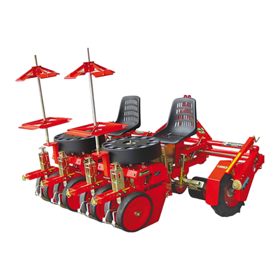
INFORMATIONS TECHNIQUES Principaux éléments L’illustration représente la machine opératrice avec deux unités de repiquage. 2000 2000 2000 2500 DUAL 12 GOLD/2 DUAL 12 GOLD/4 2000 3500 DUAL 12 GOLD/6 2000 4000 DUAL 12 GOLD/8 UN41-0540BN Caractéristiques techniques DUAL 12 DUAL 12... -
Seite 97: Déclaration De Conformité
Budrio DUAL 12 GOLD/2, DUAL 12 GOLD/4, DUAL 12 GOLD/6, DUAL 12 GOLD/8 CHECCHI & MAGLI s.r.l sont conformes aux Exigences Essentielles de Sécurité et Représentant Légal... - Seite 98 INFORMATIONS TECHNIQUES Protections contact involontaire avec les éléments en mouvement. ATTENTION L’illustration représente les carters de protection installés. Les carters (A - D - E - F) sont installés sur chaque unité Ne pas utiliser la machine sans les carters de protec- opératrice.
-
Seite 99: Signaux De Sécurité Et D'information
INFORMATIONS TECHNIQUES Signaux de sécurité et d’information L’illustration représente la position et la signification des ATTENTION plaques de sécurité. Vérifier que les plaques sont lisibles; dans le cas contraire, les nettoyer et, si elles sont endommagées, les remplacer en les appliquant dans leur position d’origine. - Seite 100 INFORMATIONS TECHNIQUES L’illustration représente la position et la signification des plaques appliquées (Rapid Shift). UN41-0543BN A) Plaque distance entre les plants (standard): ap- C) Plaque distance entre les plants (en option): ap- pliquée sur la boîte de vitesse “Rapid Shift de droite”, pliquée sur la boîte de vitesse “Rapid Shift de droite”, elle indique les pignons à...
-
Seite 101: Accessoires En Option
Porte-plateaux transversal à 2 étages cm 450 (avec châssis arrière et roues d’appui) Porte-plateaux supplémentaire à 6 niveaux Niveau porte-cagettes supplémentaire à 6 niveaux Sincromicro DUAL 12 GOLD, microgranulateur à distribution localisée et synchronisée sur toute ligne ou pour tout plant Rallonge distributeur DUAL 12 GOLD Skid DUAL 12 GOLD (glissière de compactage associée aux roues tasseuses pour terrains meubles et arides) -
Seite 102: Risques Résiduels
INFORMATIONS TECHNIQUES Risques résiduels En phase de conception et de construction, le construc- teur a veillé en particulier aux aspects de la sécurité; tou- tefois, les risques décrits persistent. - Danger de coupure et de sectionnement entre le dis- tributeur (A) et les organes internes. - Danger d’écrasement en raison d’un soulèvement inapproprié... - Seite 103 INFORMATIONS CONCERNANT LA SECURITE Lire attentivement ce manuel avant de procéder aux En cas de panne, éviter les interventions de répara- opérations d’utilisation, d’entretien ou à d’autres in- tion sur place si l’on n’est pas certain d’opérer dans terventions sur la machine opératrice. un milieu adéquat et si l’on ne dispose pas d’un équipement adéquat;...
- Seite 104 Pour limiter l’encombrement de l’emballage, la machine est démontée en un ou plusieurs colis. UN41-0004AF Dimensions indicatives de l’emballage DUAL 12 GOLD/2 DUAL 12 GOLD/4 DUAL 12 GOLD/6 DUAL 12 GOLD/8 Colis n°...
- Seite 105 INFORMATIONS CONCERNANT LA MANUTENTION ET L’INSTALLATION Levage de la machine Les opérations de levage doivent être effectuées avec ATTENTION des moyens indiqués pour la charge à soulever et par du personnel qualifié et autorisé pour sauvegarder leur Durant la phase de levage, faire attention aux oscilla- sécurité...
-
Seite 106: Déballage Et Montage
L’illustration représente sommairement le schéma de un délai de 8 jours à compter de la réception de la ma- montage de la machine opératrice. chine. DUAL 12 GOLD/2 DUAL 12 GOLD/4 DUAL 12 GOLD/6 DUAL 12 GOLD/8 UN41-0546BN Langue française... - Seite 107 INFORMATIONS CONCERNANT LES REGLAGES Recommandations de sécurité pour les réglages Les interventions de réglage doivent être effectuées de contact retirée du tableau de bord; prendre tou- sur un terrain plat et compact; le moteur du tracteur tes les mesures nécessaires pour opérer en toute sé- doit être coupé, le frein de stationnement tiré, la clé...
- Seite 108 INFORMATIONS CONCERNANT LES REGLAGES Suivre les indications fournies ci-après en ce qui concer- ne le réglage de l’inclinaison des roues de compactage. 1) Desserrer les vis (A). 2) Faire pivoter le support (B) pour modifier l’inclinaison des roues de compactage. 3) Serrer les vis (A).
- Seite 109 INFORMATIONS CONCERNANT LES REGLAGES Réglage de la profondeur de repiquage Suivre les instructions fournies. 1) Agir sur l’arrêt (A) pour libérer la poignée. 2) Tourner la poignée (B) pour augmenter ou réduire la profondeur du sillon. 3) Après le réglage bloquer la poignée (B) avec l’arrêt (A).
- Seite 110 INFORMATIONS CONCERNANT LES REGLAGES Réglage du racloir des roues de flottaison Le racloir sert à nettoyer les roues de flottaison en élimi- nant la terre et les détritus qui s’y accumulent. Effectuer les opérations décrites pour procéder au ré- glage. 1) Desserrer les vis (A).
- Seite 111 INFORMATIONS CONCERNANT LES REGLAGES Réglage de la distance entre les rangs accouplés Au cours de la conception, le fabricant a prévu trois ty- La machine est livrée avec la “gamme de distances entre pes de “gamme de distances entre rangs accouplés” (voir rangs accouplés”...
- Seite 112 INFORMATIONS CONCERNANT LES REGLAGES Réglage de la distance standard entre rangs accouplés (35 - 39) La cote inférieure (x) doit être vers l’intérieur de l’unité INFORMATION de repiquage et la cote supérieure (y) vers l’extérieur. Le réglage n’est possible que si la position du disque Si cette condition n’est pas respectée, il faut inverser les flexible (A) par rapport au tube de chute (B) corres- châssis latéraux de l’unité...
- Seite 113 INFORMATIONS CONCERNANT LES REGLAGES Modification de l’intervalle des distances standards entre les rangs accouplés Pour modifier l’intervalle des distances entre les rangs accouplés de 40 ÷50 à 35 ÷ 39 et vice versa, procéder comme suit. Soulever la machine opératrice. PRUDENCE Soulever la machine le moins possible pour effectuer l’opération.
- Seite 114 INFORMATIONS CONCERNANT LES REGLAGES Réglage symétrique du disque flexible par rapport au soc UN41-0552BN Pour le réglage, suivre la description. INFORMATION 1) Desserrer les vis (A). Vérifier que le disque flexible ne frotte pas sur le soc. 2) Centrer le disque flexible (B) par rapport au soc (C). 3) Serrer les vis (A).
- Seite 115 INFORMATIONS CONCERNANT LES REGLAGES Réglage de la distance entre les plants La distance entre deux plants est déterminée par le nom- bre de dents des pignons installés. On peut monter différentes séries de pignons pour obte- nir la distance nécessaire entre les plants. Choisir le rapport de transmission correct si les machines sont équipées de la boîte de vitesses “Rapid Shift”.
- Seite 116 INFORMATIONS CONCERNANT LES REGLAGES EQUIPEMENT 14 - 50 RAPID SHIFT (G) Distance entre les plants N° dents des pignons inches z 1 z 2 z 3 5 - 1/2 6 - 3/4 7 - 7/8 8 - 5/8 9 - 1/2 10 - 1/4 12 -3/8 13 - 3/8...
- Seite 117 INFORMATIONS CONCERNANT LES REGLAGES Réglage de la phase distributeur-éjecteur Quand le plant tombe dans le soc (A), l’éjecteur (B) doit Régler la phase entre le distributeur et l’éjecteur en fonc- se trouver en arrière pour commencer la poussée d’éjec- tion des différentes vitesses de repiquage. tion.
- Seite 118 INFORMATIONS CONCERNANT LES REGLAGES Réglage de la phase d’ouverture des coupes UN41-0555BN Suivant le type de plants et de la vitesse de rotation, il Pour le réglage, suivre la description. peut arriver que les plants, en descendant du distribu- 1) Desserrer les vis (E) et agir sur la came (B). teur, heurtent latéralement l’entrée du tube de chute, Tourner la came dans le sens (1) pour anticiper provoquant une descente non perpendiculaire du...
- Seite 119 INFORMATIONS CONCERNANT LES REGLAGES Réglage de la charge de l’unité de repiquage UN41-0556BN Le groupe de réglage est généralement monté dans la Le poids (charge) à appliquer sur les roues de compac- position (A1). tage est obtenu grâce à l’action combinée des groupes Le groupe (A) dans la position (A1) permet de réduire le de réglage (A) et (B).
-
Seite 120: Description Des Commandes
INFORMATIONS CONCERNANT L’UTILISATION Recommandations concernant la sécurité durant l’utilisation Ne confier l’utilisation de la machine qu’à du person- Ne pas dépasser les pentes maximales admises pour nel autorisé, en bonne santé, dûment formé et muni le tracteur lorsque l’équipement est appliqué (voir du permis de conduire pour les tracteurs. - Seite 121 INFORMATIONS CONCERNANT L’UTILISATION Attelage et dételage de la machine opératrice du tracteur ATTENTION ATTENTION Le raccordement de la machine opératrice au tracteur N’atteler la machine opératrice qu’à une tracteur est l’un des moments les plus dangereux car il pour- d’une puissance adéquate et équipé d’un dispositif rait exiger l’intervention simultanée de plusieurs per- de levage conforme aux normes en vigueur respec- sonnes accomplisant des manœuvres synchronisées...
-
Seite 122: Réglage Du Siège
INFORMATIONS CONCERNANT L’UTILISATION Réglage du siège Une mauvaise position de travail fatigue l’opérateur qui risque d’effectuer des opérations incorrectes; ainsi, avant de commencer à travailler, régler et bloquer le siège dans la position de confort maximum. Procéder comme suit. 1) Desserrer les vis (A) et régler le siège en hauteur. 2) Serrer les vis (A) pour bloquer le siège dans la posi- tion appropriée. - Seite 123 INFORMATIONS CONCERNANT L’UTILISATION Modalités de repiquage Repiquer les plants dans un terrain préalablement plant et en favoriser la prise. émietté à la herse ou avec une sarcleuse et légèrement Ne pas opérer sur des terrains trop meubles, trop com- tassé en surface. pacts ou détrempés pour ne pas compromettre la bonne Ne pas charger dans le distributeur des plants avec une qualité...
- Seite 124 INFORMATIONS CONCERNANT L’UTILISATION d’avance adéquate de manière à déposer dans le dis- 6) Les opérateurs à bord de la machine opératrice doi- tributeur au moins 30 plants à la minute et obtenir vent vérifier constamment la qualité de repiquage; une phase correcte entre le plant et l’éjecteur. en cas d’anomalies, demander l’arrêt du tracteur et 5) Avancer avec le tracteur pour commencer la phase adopter les mesures de correction (voir “Informations...
-
Seite 125: Circulation Sur La Voie Publique
INFORMATIONS CONCERNANT L’UTILISATION Circulation sur la voie publique Durant le transfert du groupe machine opératrice-trac- ATTENTION teur, observer les prescriptions du code de la route. Il est obligatoire de boquer l’attelage à trois points avec Il est interdit de transporter des personnes et/ou des les contre-fiches (A) pour empêcher toute oscillation de choses sur la machine opératrice. - Seite 126 INFORMATIONS CONCERNANT L’ENTRETIEN Recommandations de sécurité pour l’entretien Les interventions d’entretien doivent être effectuées à l’exploitation, consulter les interventions d’entretien sur un terrain plat et compact; le moteur du tracteur ordinaire prévues dans le manuel d’instructions. doit être coupé, le frein de stationnement tiré, la clé de Pour les interventions extraordinaires, disposer d’un contact retirée du tableau de bord;...
-
Seite 127: Contrôle Des Pneus
INFORMATIONS CONCERNANT L’ENTRETIEN Contrôle des pneus Vérifier l’état d’usure des pneus et la présence de déchi- (voir tableau “Caractéristiques techniques”). rures ou de signes de vieillissement; le cas échéant, les Le contrôle de la pression doit être effectué avec le poids remplacer. - Seite 128 INFORMATIONS CONCERNANT L’ENTRETIEN Problèmes, causes, solutions La liste indique quelques problèmes et les solutions correspondantes pouvant se présenter durant la phase de tra- vail. Problème Cause probable Solution Procéder au réglage (voir “Réglage de la profondeur de repiquage”) La profondeur de repiquage est Régler la charge de l’unité...
- Seite 129 INFORMATIONS CONCERNANT L’ENTRETIEN Schéma des points de lubrification Lubrifier les organes illustrés en respectant les délais et éviter de contaminer le lubrifiant distribué. les modalités indiqués. Utiliser une graisse universelle pour moteurs de machi- Avant d’effectuer la lubrification, nettoyer soigneuse- nes agricoles et industrielles, hydrofuge avec un point ment les composants concernés et les graisseurs pour de goutte à...
- Seite 130 INFORMATIONS CONCERNANT LES REMPLACEMENTS Recommandations de sécurité pour les remplacements Le remplacement des composants usés ou endom- ploitation ayant les caractéristiques indiquées par magés doit être effectué avec des pièces de rechange la législation en vigueur en la matière (équipement originales.
- Seite 131 INFORMATIONS CONCERNANT LES REMPLACEMENTS Remplacement de la chaîne des roues motrices UN41-0510MM Pour cette opération, suivre la description. Monter une nouvelle chaîne. Actionner le levier (E) pour soulever la roue afin de INFORMATION réduire la tension de la chaîne. Monter la chaîne en orientant le maillon de jonction Desserrer les boutons (A).
- Seite 132 INFORMATIONS CONCERNANT LES REMPLACEMENTS Remplacement de la chaîne de l’unité de repiquage UN41-0565BN Procéder comme suit. Démonter le maillon de jonction (H). Desserrer les vis (A) et démonter le carter (B). Enlever la chaîne des pignons. Desserrer les écrous (C) et démonter le carter (D). Monter la nouvelle chaîne sur les pignons et le galo- Desserrer les écrous (E) et démonter le carter (F).
- Seite 133 INFORMATIONS CONCERNANT LES REMPLACEMENTS Remplacement du disque flexible UN41-0566BN Pour cette opération, suivre la description. INFORMATION Desserrer la vis (F). Vérifier que le dispositif Plant Control (H) se trouve à Enlever le carter (G). l’intérieur du soc. Desserrer l’écrou papillon (A). Tourner le levier de sécurité...
- Seite 134 INFORMATIONS CONCERNANT LES REMPLACEMENTS Remplacement du soc Suivre les instructions fournies. 1) Enlever l’anneau élastique (A). 2) Desserrer l’écrou papillon (B). 3) Soulever le dispositif de blocage (D) et le maintenir dans cette position. 4) Pousser le soc vers l’avant et le tour- ner vers le bas.
- Seite 135 INHALTSANGABE 1 ALLGEMEINE INFORMATIONEN ......................1 2 TECHNISCHE INFORMATIONEN ......................3 3 INFORMATIONEN ZUR SICHERHEIT ....................11 4 INFORMATIONEN ZUR BEWEGUNG UND ZUR INSTALLATION ..........12 5 INFORMATIONEN ZU DEN EINSTELLUNGEN .................. 15 6 INFORMATIONEN ZUR BENUTZUNG ....................28 7 INFORMATIONEN ZUR WARTUNG...................... 34 8 INFORMATIONEN ZU DEN ERSETZUNGEN..................
- Seite 136 Fahrt auf öffentlichen Straßen ........................33 Funktionsstörungen, Ursachen und Behebung .................. 36 Geräusch ................................9 Glossar ...................................2 Haftungsausschluss ............................2 Hauptelemente ..............................3 Inhaltsangabe ..............................III Konformitätserklärung ............................5 Kontrolle der Reifen ............................35 Längere Nichtbenutzung der Arbeitsmaschine .................. 33 Plan der Schmierungspunkte ........................37 Plant Control Einstellung ..........................
-
Seite 137: Allgemeine Informationen
ALLGEMEINE INFORMATIONEN Zweck des Handbuches Das vorliegenden Handbuch wurde vom Hersteller Zur Hervorhebung von Teilen des Textes, die für die Si- verfasst, um die erforderlichen Informationen und die cherheit relevant sind oder die wichtige Informationen anzuwendenden Kriterien zu liefern, die alle befolgen enthalten, wurden einige Symbole angewendet, deren müssen, die mit der Umpflanzmaschine umgehen, die Bedeutung im Folgenden beschrieben wird. -
Seite 138: Haftungsausschluss
ALLGEMEINE INFORMATIONEN Haftungsausschluss Die Arbeitsmaschine wird zu den Bedingungen geliefert, - Unterlassungen bei der Wartung die zum Zeitpunkt des Verkaufs gültig sind und im Kauf- - vollständige oder teilweise Nichtbeachtung der An- vertrag angegeben werden. weisungen in diesem Handbuch - die Benutzung von Ersatzteilen von Drittanbietern - Alle nicht vom Hersteller genehmigten Änderungen oder von Ersatzteilen für andere Modelle - unsachgemäßer Gebrauch der Arbeitsmaschine... -
Seite 139: Allgemeine Beschreibung
TECHNISCHE INFORMATIONEN Allgemeine Beschreibung Die Arbeitsmaschine wurde für das Umpflanzen von von der Fahrt des Schleppers. Pflanzen (zum Beispiel kleinen Gemüsepflanzen, Blumen, Die Pflanzen fallen aus dem Verteiler in die von den Pflug- Tabakpflanzen, in Gewächshäusern vorgezogenen Pflan- scharen geschaffenen Furchen und die Stampfräder ver- zen usw.) entwickelt und konstruiert, die in Torf mit koni- füllen und drücken das Erdreich um die Scholle der Pflan- scher oder zylindrischer Form wurzeln, auch mit geringen... -
Seite 140: Abmessungen
TECHNISCHE INFORMATIONEN Abmessungen Die Abbildung gibt die Abmessungen der Arbeitsmaschine wieder. 2000 2000 2000 2500 DUAL 12 GOLD/2 DUAL 12 GOLD/4 2000 3500 DUAL 12 GOLD/6 2000 4000 DUAL 12 GOLD/8 UN41-0540BN Technische Eigenschaften DUAL 12 DUAL 12 DUAL 12... -
Seite 141: Konformitätserklärung
40054 - BUDRIO (BOLOGNA) - ITALIA UNI EN 13857 zur Maschinensicherheit. erklärt auf eigene Verantwortung, dass die Umpflanzma- schinen: Budrio DUAL 12 GOLD/2, DUAL 12 GOLD/4, DUAL 12 GOLD/6, DUAL 12 GOLD/8 CHECCHI & MAGLI s.r.l den wesentlichen Anforderungen der EU-Richtlinie Gesetzlicher Vertreter... - Seite 142 TECHNISCHE INFORMATIONEN Schutzvorrichtungen meiden. ACHTUNG Die Abbildung zeigt die installierten Schutzabdeckun- gen. Benutzen Sie die Maschine nie ohne Schutzvorrich- Die Schutzverkleidungen (A - D - E - F) werden bei allen tungen. Arbeitsmaschinen installiert. Die Arbeitsmaschine weist Schutzvorrichtungen für die Die Schutzabdeckungen (B - C) sind an jedem Antrieb- Antriebsorgane auf, um Unfälle durch den unbeabsich- srad installiert.
-
Seite 143: Warn- Und Hinweisschilder
TECHNISCHE INFORMATIONEN Warn- und Hinweisschilder Die Abbildung gibt die Position und die Bedeutung der ACHTUNG Sicherheitsschilder an. Stellen Sie sicher, dass die Schilder leserlich sind; rei- nigen Sie sie anderenfalls oder bringen Sie neue in der Originalposition an. UN41-0542BN A) Gefahrenschild: bitte lesen Sie das Handbuch zur F) Informationsschild: die Kette im Inneren der Benutzung und Wartung vor der Benutzung der Ar- Schutzverkleidung schmieren, auf der das Schild an-... - Seite 144 TECHNISCHE INFORMATIONEN Die Abbildung zeigt die Position und die Bedeutung der angebrachten Schilder (Rapid Shift). UN41-0543BN A) Schild zum Pflanzabstand (Standard): gibt an der C) Schild zum Pflanzabstand (optional): gibt an der Schaltung “Rapid Shift rechts” angebracht, je nach Schaltung “Rapid Shift rechts” angebracht, je nach dem Pflanzabstand (14 - 50) die zu wählenden Ritzel dem Pflanzabstand (26 - 81) die zu wählenden Ritzel B) Schild zum Pflanzabstand (Standard): gibt an der...
-
Seite 145: Sonderzubehör
Sincromicro DUAL 12 GOLD, Mikrogranulatstreuer zur stellenweisen und synchronisierten Verteilung in allen Reihen oder an jeder Pflanze Verlängerung für Verteiler DUAL 12 GOLD Skid DUAL 12 GOLD (Verdichterschlitten der Verdichtungsräder für weiche und trockene Böden) Vorrichtung zur Verlegung des Bewässerungsschlauchs Kit für Scheiben vor der Pflugschar Eingrabe-Verteiler mit Feder (für Mikro-Granulator und/oder Düngerstreuer) -
Seite 146: Restrisiken
TECHNISCHE INFORMATIONEN Restrisiken Der Hersteller hat in der Phase der Entwicklung und Kon- struktion besondere Sorgfalt auf die Sicherheitsaspekte verwendet; die beschriebenen Risiken konnten jedoch nicht vermieden werden. - Schneid- und Abschergefahr zwischen dem Verteiler (A) und den Elementen im Inneren. - Gefahr von Quetschungen beim falschen Heben der Maschine. -
Seite 147: Informationen Zur Sicherheit
INFORMATIONEN ZUR SICHERHEIT Bitte lesen Sie das vorliegende Handbuch aufmerk- Tragen Sie während der Benutzung die Arbeitsklei- sam vor sämtlichen Eingriffen zur Benutzung und dung und benutzen Sie die Personenschutzvorrich- Wartung oder sonstigen Eingriffen an der Arbeits- tungen, die von den geltenden Bestimmungen zur maschine. -
Seite 148: Informationen Zur Bewegung Und Zur Installation
Die Abbildung gibt den üblicherweise verwendeten Ver- sort ausgewählt. packungstyp wieder. Zur Begrenzung der Abmessungen der Verpackung wird UN41-0004AF Unverbindliche Abmessungen der Verpackung DUAL 12 GOLD/2 DUAL 12 GOLD/4 DUAL 12 GOLD/6 DUAL 12 GOLD/8 Packstücke n° Bewegung und Heben der Verpackung... -
Seite 149: Anheben Der Arbeitsmaschine
INFORMATIONEN ZUR BEWEGUNG UND ZUR INSTALLATION Anheben der Arbeitsmaschine Die Hubvorgänge müssen mit für die zu hebende Last ACHTUNG geeigneten Mitteln und durch zugelassenes Fachperso- nal ausgeführt werden, um die eigene Sicherheit und Achten Sie beim Heben auf die Schwingungen der die der bei den Arbeiten einbezogenen Personen zu ga- Last, da die Aufnahmestelle niemals genau dem rantieren. -
Seite 150: Auspacken Und Montage
Sie bei Schäden innerhalb von 8 Tagen Die Abbildung zeigt zusammenfassend das Montage- vom Erhalt der Maschine den Händler oder direkt den schema der Arbeitsmaschine. Herstellern. Die Verpackung muss unter Beachtung der DUAL 12 GOLD/2 DUAL 12 GOLD/4 DUAL 12 GOLD/6 DUAL 12 GOLD/8 UN41-0546BN... -
Seite 151: Informationen Zu Den Einstellungen
INFORMATIONEN ZU DEN EINSTELLUNGEN Sicherheitsempfehlungen für die Einstellungen Die Einstelleingriffe müssen auf ebenem und kom- Zündschlüssel ausgeführt werden; dabei müssen paktem Untergrund mit abgeschaltetem Schlepper, sämtliche Maßnahme angewendet werden, die zur angezogener Feststellbremse und abgezogenem Gewährleistung der Sicherheit erforderlich sind. Einstellung des Abstands der Verdichtungsräder zur Pflugschar Die Verdichtungsräder (B) dienen zum Umwälzen und Verdichten des Erdreiches um die umgepflanzten Pflan-... -
Seite 152: Einstellung Des Schabers Der Verdichterräder
INFORMATIONEN ZU DEN EINSTELLUNGEN Gehen Sie zum Einstellen der Neigung der Stampfräder wie beschrieben vor. 1) Lösen Sie die Schrauben (A). 2) Drehen Sie die Halterung (B), um die Neigung der Stampfräder zu ändern. 3) Ziehen Sie die Schrauben (A) an. Führen Sie die gleichen Arbeitsgänge aus, um die Stampfräder an den anderen installierten Pflanzeinhei- ten einzustellen. -
Seite 153: Einstellung Der Umpflanztiefe
INFORMATIONEN ZU DEN EINSTELLUNGEN Einstellung der Umpflanztiefe Gehen Sie wie beschrieben vor. 1) Betätigen Sie den Feststeller (A), um den Knauf zu lö- sen. 2) Drehen Sie den Knauf (B), um die Tiefe der Pflugschar zu erhöhen oder zu verringern. 3) Nach Vornahme der Einstellung arretieren Sie den Knauf (B) mit dem Feststeller (A). -
Seite 154: Einstellen Des Abstreifers Der Schwimmräder
INFORMATIONEN ZU DEN EINSTELLUNGEN Einstellen des Abstreifers der Schwimmräder Der Abstreifer dient zum Reinigen der Schwimmräder vom angesammelten Erdreich und Schmutz. Zur Einstellung die beschriebenen Arbeitsgänge ausfüh- ren. 1) Lösen Sie die Schrauben (A). 2) Heben oder senken Sie den Abstreifer (B) des Schwimmrades bis zum Erreichen der gewünschten Position. -
Seite 155: Einstellen Des Reihenabstandes
INFORMATIONEN ZU DEN EINSTELLUNGEN Einstellen des Reihenabstandes Der Hersteller hat beim Entwurf drei Arten von “Reihen- Die Arbeitsmaschine wird mit dem bei Bestellung ange- abstandsbereichen” vorgesehen (siehe Tabelle “Techni- gebenen ”Reihenabstandsbereich” geliefert. sche Eigenschaften“). Einstellung des Standard-Reihenabstandes (40 - 50) INFORMATION Der Mindestwert (x) muss sich zum Äußeren der Pflanz- einheit und der Höchstwert (y) zum Inneren befinden. -
Seite 156: Einstellen Des Bereichs Der Optionalen Reihenabstände
INFORMATIONEN ZU DEN EINSTELLUNGEN Einstellung des Standard-Reihenabstandes (35 - 39) Der Mindestwert (x) muss sich zum Inneren der Pflanz- INFORMATION einheit und der Höchstwert (y) zum Äußeren befinden. Die Einstellung ist nur möglich, wenn die Position Wird diese Bedingung nicht erfüllt, müssen die seitlichen der flexiblen Platte (A) in Bezug zum Fallrohr (B) der Rahmen der Pflanzeinheit vertauscht werden (siehe „Be- Darstellung in der Abbildung entspricht. -
Seite 157: Bereichswechsel Der Standard-Reihenabstände
INFORMATIONEN ZU DEN EINSTELLUNGEN Bereichswechsel der Standard-Reihenabstände Gehen Sie, um den Abstand zwischen den Standard-Rei- henabständen von 40 ÷50 auf den Bereich 35 ÷ 39 und umgekehrt zu ändern, wie beschrieben vor. Heben Sie die Arbeitsmaschine an. VORSICHT Heben Sie die Arbeitsmaschine nur soweit wie zum Ausführen des Vorgangs unbedingt nötig ist. -
Seite 158: Symmetrische Einstellung Der Flexiblen Platte Mit Der Pflugschar
INFORMATIONEN ZU DEN EINSTELLUNGEN Symmetrische Einstellung der flexiblen Platte mit der Pflugschar UN41-0552BN Gehen Sie bei der Einstellung wie beschrieben vor. INFORMATION 1) Lösen Sie die Schrauben (A). Prüfen Sie, dass die flexible Platte nicht auf der Pflug- 2) Zentrieren Sie die flexible Platte (B) zur Pflugschar schar reibt. -
Seite 159: Einstellung Des Pflanzenabstands
INFORMATIONEN ZU DEN EINSTELLUNGEN Einstellung des Pflanzenabstands Der Abstand zwischen einer Pflanze und der folgenden wird durch die Anzahl der Zähne der installierten Ritzel bestimmt. Es können verschiedene Ritzelserien montiert werden, um den gewünschten Pflanzenabstand zu erzielen. Wählen Sie das richtige Übertragungsverhältnis, wenn die Arbeitsmaschinen mit der Schaltung “Rapid Shift“... - Seite 160 INFORMATIONEN ZU DEN EINSTELLUNGEN AUSSTATTUNG 14 - 50 RAPID SHIFT (LINKS) Pflanzenabstand Zahnzahl Ritzel inches 5 - 1/2 6 - 3/4 7 - 7/8 8 - 5/8 9 - 1/2 10 - 1/4 12 -3/8 13 - 3/8 14 - 5/8 15 - 3/4 16 - 1/2 17 - 3/4...
-
Seite 161: Einstellung Der Phase Verteiler/Auswerfer
INFORMATIONEN ZU DEN EINSTELLUNGEN Einstellung der Phase Verteiler/Auswerfer Wenn die Pflanze in die Pflugschar (A) fällt, muss sich der Regeln Sie die richtige Phase zwischen Verteiler und Auswerfer (B) in eingefahrener Position befinden, um Auswerfer entsprechend der unterschiedlichen Pflanz- den Auswurfschub zu beginnen. geschwindigkeiten. -
Seite 162: Einstellen Der Öffnungsphase Der Becher
INFORMATIONEN ZU DEN EINSTELLUNGEN Einstellen der Öffnungsphase der Becher UN41-0555BN Je nach der Pflanzenart und der Rotationsgeschwindig- Gehen Sie bei der Einstellung wie beschrieben vor. keit kann es geschehen, dass die Pflanzen, wenn sie aus 1) Lockern Sie die Schrauben (E) und betätigen Sie den dem Verteiler fallen, seitlich gegen die Öffnung des Fall- Nocken (B). -
Seite 163: Einstellung Der Last Der Umpflanzeinheit
INFORMATIONEN ZU DEN EINSTELLUNGEN Einstellung der Last der Umpflanzeinheit UN41-0556BN Die Regelvorrichtung wird gewöhnlich in Position (A1) Das Gewicht (Last), das auf die Stampfräder ausgeübt montiert. werden muss, wird durch die kombinierte Wirkung der Die Baugruppe (A) in Position (A1) ermöglicht es, das Regelungen (A) und (B) erzielt. -
Seite 164: Informationen Zur Benutzung
INFORMATIONEN ZUR BENUTZUNG Sicherheitsempfehlungen für den Gebrauch Gestatten Sie die Benutzung der Maschine aus- Überschreiten Sie nicht das max. zulässige Gefälle schließlich dazu befugtem Personal mit gutem Ge- des Schleppers mit angebrachter Ausrüstung (siehe sundheitszustand, angemessener Ausbildung sowie Benutzungshandbuch des Schleppers). Führerschein für den Schlepper. -
Seite 165: Anbringen Und Ablösen Der Arbeitsmaschine Am Schlepper
INFORMATIONEN ZUR BENUTZUNG Anbringen und Ablösen der Arbeitsmaschine am Schlepper ACHTUNG ACHTUNG Das Anbringen der Arbeitsmaschine am Schlepper Schließen Sie die Arbeitsmaschine nur an einen ist einer der gefährlichsten Momente, da gleichzeitig Schlepper mit ausreichender Leistung sowie mit mehrere Personen mit synchronisierten Manövern Kraftheber an, der den geltenden Bestimmungen des Fahrers des Schleppers und der Bediener am Bo- entspricht;... -
Seite 166: Positionieren Des Sitzes
INFORMATIONEN ZUR BENUTZUNG Positionieren des Sitzes Eine falsche Arbeitsposition ermüdet den Bediener, der dann falsche Arbeitsgänge ausführen könnte; vor Beginn des Arbeitsvorganges regeln und arretieren Sie deshalb den Sitz in der Position für maximalen Komfort. Gehen Sie wie beschrieben vor. 1) Lösen Sie die Schrauben (A) und stellen Sie die Sitz- höhe ein. -
Seite 167: Umpflanzmodalität
INFORMATIONEN ZUR BENUTZUNG Umpflanzmodalität Das Umpflanzen muss in zuvor mit Eggen oder Fräsen der Pflanze zu begünstigen. gelockertem und an der Oberfläche leicht verdichtetem Arbeiten Sie nicht auf sehr weichem, sehr kompaktem Erdreich erfolgen. oder sehr feuchtem Boden, um die Qualität des Um- Laden Sie in den Verteiler keine Pflanzen mit unvollstän- pflanzens nicht zu beeinträchtigen. -
Seite 168: Arbeit Bei Nacht Oder Bei Schlechter Sicht
INFORMATIONEN ZUR BENUTZUNG Fahrgeschwindigkeit vereinbaren, so dass zumindest 6) Die Bediener an Bord der Arbeitsmaschine müssen die Qualität des Umpflanzens ständig überprüfen. 30 Pflanzen pro Minute in den Verteiler gesetzt wer- Halten Sie bei Anomalien den Schlepper an und neh- den, um eine richtige Phasierung von Pflanze und men Sie geeignete Korrekturmaßnahmen vor (siehe Auswerfer zu erzielen. -
Seite 169: Fahrt Auf Öffentlichen Straßen
INFORMATIONEN ZUR BENUTZUNG Fahrt auf öffentlichen Straßen Beachten Sie beim Fahren mit dem Schlepper und ange- ACHTUNG bauter Arbeitsmaschine die Bestimmungen der Straßen- verkehrsordnung. Es ist untersagt, Personen und/oder Sachen auf der Der Dreipunktanschluss muss mit den entsprechenden Arbeitsmaschine zu transportieren. Streben (A) blockiert werden, um sämtliche Schwankun- Entfernen Sie vor der Fahrt auf der Straße die Bretter gen der Arbeitsmaschine am Schlepper zu vermeiden;... - Seite 170 INFORMATIONEN ZUR WARTUNG Sicherheitsempfehlungen zur Wartung Die Wartungseingriffe müssen auf ebenem und kom- sungshandbuch beschrieben werden, können im Un- paktem Untergrund mit abgeschaltetem Schlepper, ternehmen durchgeführt werden. angezogener Feststellbremse und abgezogenem Für außerordentliche Eingriffe ist eine Werkstatt er- Zündschlüssel ausgeführt werden; dabei müssen forderlich, die den Bestimmungen der geltenden Ge- sämtliche Maßnahme angewendet werden, die zur setzgebung entspricht (angemessene Ausrüstung,...
-
Seite 171: Kontrolle Der Reifen
INFORMATIONEN ZUR WARTUNG Kontrolle der Reifen Überprüfen Sie den Abnutzungszustand der Reifen; falls Die Kontrolle des Reifendrucks muss mit auf dem Boden sie Risse oder Anzeichen von Alterung aufweisen, müs- lastendem Gewicht der Arbeitsmaschine und ohne Ge- sen sie ersetzt werden. wicht an Bord (Personen oder Sachen) vorgenommen Prüfen Sie, ob es notwendig ist, den Reifendruck zu korri- werden. -
Seite 172: Funktionsstörungen, Ursachen Und Behebung
INFORMATIONEN ZUR WARTUNG Funktionsstörungen, Ursachen und Behebung Das Verzeichnis führt einige Funktionsstörungen auf, die während der Arbeit auftreten können, sowie ihre Behe- bung. Funktionsstörung Mögliche Ursache Abhilfe Nehmen Sie die Einstellung vor (siehe “Einstellung der Umpflanztiefe”) Die Umpflanztiefe ist falsch Regeln Sie die Last der Pflanzeinheit (siehe “Einstellen der Last der Die umgepflanzte Pflanze sitzt zu... -
Seite 173: Plan Der Schmierungspunkte
INFORMATIONEN ZUR WARTUNG Plan der Schmierungspunkte Schmieren Sie die abgebildeten Organe unter Beach- Verwenden Sie wasserabstoßendes Universalfett mit tung der angegebenen Zeiten und Modalitäten. einem Tropfpunkt von 180° für Landwirtschafts- und In- Reinigen Sie vor dem Schmieren sorgfältig die betroffe- dustriemaschinen. -
Seite 174: Informationen Zu Den Ersetzungen
INFORMATIONEN ZU DEN ERSETZUNGEN Sicherheitsempfehlungen für die Auswechslungen Bei der Ersetzung von abgenutzten oder beschädig- statt erforderlich, die den Bestimmungen der gel- ten Komponenten dürfen ausschließlich Originaler- tenden Gesetzgebung entspricht (angemessene satzteile verwendet werden. Ausrüstung, geeignetes Personal usw.); wenden Sie Für außerordentliche Eingriffe (die im vorliegenden sich anderenfalls an eine Vertragswerkstatt. -
Seite 175: Ersetzung Der Kette Der Antriebsräder
INFORMATIONEN ZU DEN ERSETZUNGEN Ersetzung der Kette der Antriebsräder UN41-0510MM Gehen Sie für diesen Vorgang wie beschrieben vor. Montieren Sie eine neue Kette. Betätigen Sie den Hebel (E), um das Rad mit dem INFORMATION Zweck zu heben, die Spannung der Kette zu verrin- Montieren Sie die Kette, so dass das Verbindung- gern. -
Seite 176: Ersetzung Der Kette Der Umpflanzeinheit
INFORMATIONEN ZU DEN ERSETZUNGEN Ersetzung der Kette der Umpflanzeinheit UN41-0565BN Gehen Sie für diesen Vorgang wie beschrieben vor. Bauen Sie das Verbindungsglied (H) aus. Entfernen Sie die Kette von den Ritzeln. Lösen Sie die Schrauben (A) und entfernen Sie die Montieren Sie die neue Kette auf den Ritzeln und Verkleidung (B). -
Seite 177: Austausch Der Flexiblen Platte
INFORMATIONEN ZU DEN ERSETZUNGEN Austausch der flexiblen Platte UN41-0566BN Gehen Sie für diesen Vorgang wie beschrieben vor. INFORMATION Lösen Sie die Schraube (F). Prüfen Sie, ob sich die Plant Control- Vorrichtung (H) Entfernen Sie die Schutzverkleidung (G). im Inneren der Pflugschar befindet. Lockern Sie die Flügelmutter (A). -
Seite 178: Ersetzung Der Pflugschar
INFORMATIONEN ZU DEN ERSETZUNGEN Ersetzung der Pflugschar 1) Entfernen Sie den Elastikring (A). 2) Lösen Sie die Flügelmutter (B). 3) Heben Sie die Blockiervorrichtung (D) an und halten sie sie angehoben. 4) Schieben Sie die Pflugschar nach vorn und drehen Sie sie nach unten. 5) Halten Sie die Pflugschar fest und ent- fernen Sie die Schraube (C) und die Unterlegscheibe (E). - Seite 179 INDICE 1 INFORMACIONES GENERALES .......................1 2 INFORMACIONES TECNICAS ........................3 3 INFORMACIONES SOBRE SEGURIDAD ....................11 4 INFORMACIONES SOBRE DESPLAZAMIENTO E INSTALACION ..........12 5 INFORMACIONES SOBRE LAS REGULACIONES................15 6 INFORMACIONES SOBRE EL USO ....................... 28 7 INFORMACIONES SOBRE EL MANTENIMIENTO ................34 8 INFORMACIONES SOBRE LAS SUSTITUCIONES ................
- Seite 180 Objeto del manual ............................1 Posicionamiento del asiento ........................30 Principales componentes ..........................3 Protecciones ................................6 Recomendaciones a observar para un uso seguro ................28 Recomendaciones de seguridad para el mantenimiento ............... 34 Recomendaciones de seguridad para las regulaciones ..............15 Recomendaciones de seguridad para las sustituciones ..............38 Recomendaciones sobre seguridad durante el desplazamiento y el transporte ....
-
Seite 181: Informaciones Generales
INFORMACIONES GENERALES Objeto del manual El manual ha sido realizado por el fabricante para pro- los centros de asistencia autorizados. porcionar las informaciones necesarias y los criterios a Para destacar algunas partes del texto, importantes para seguir a todas las personas que deben interactuar con los fines de la seguridad o para indicar informaciones de la trasplantadora, que a continuación en el manual tam- mayor relevancia, han sido utilizados algunos símbolos... -
Seite 182: Exclusión De Responsabilidad
INFORMACIONES GENERALES Exclusión de responsabilidad La máquina operadora se entrega en las condiciones vá- - la falta de mantenimiento lidas existentes en el momento de la compra que aparez- - la inobservancia total o parcial de las instrucciones de can especificadas en el contrato de venta. este manual - Cualquier modificación no autorizada por el fabricante - el uso de recambios no originales o que no sean espe-... -
Seite 183: Descripción General
INFORMACIONES TECNICAS Descripción general La máquina operadora ha sido diseñada y fabricada para Las plantas caen por gravedad desde el distribuidor en colocar en terreno plantas (por ejemplo plantas hortíco- los surcos creados por las rejas y las ruedas apisonado- las, florícolas, de tabaco, cultivadas en viveros, etc.) radi- ras refuerzan y prensan el terreno sobre el terrón de la cadas en terrones de turba de forma cónica o piramidal... - Seite 184 INFORMACIONES TECNICAS Dimensiones En la ilustración se indican las dimensiones de las máquinas operadoras. 2000 2000 2000 2500 DUAL 12 GOLD/2 DUAL 12 GOLD/4 2000 3500 DUAL 12 GOLD/6 2000 4000 DUAL 12 GOLD/8 UN41-0540BN Características técnicas DUAL 12 DUAL 12...
-
Seite 185: Declaración De Conformidad
13857 relativas a la seguridad de la maquinaria. declara bajo su propia responsabilidad que las máquinas trasplantadoras: Budrio DUAL 12 GOLD/2, DUAL 12 GOLD/4, DUAL 12 GOLD/6, DUAL 12 GOLD/8 CHECCHI & MAGLI s.r.l reúnen los Requisitos Esenciales sobre Seguridad y Pro- Representante legal tección de la Salud establecidos por la Directiva 2006/42/... - Seite 186 INFORMACIONES TECNICAS Protecciones La ilustración presenta los cárteres de protección insta- ATENCION lados. Los cárteres (A - D - E - F) han sido instalados en todas las No usar la máquina sin sus cárteres de protección. unidades operadoras. La máquina operadora cuenta con elementos de protec- Los cárteres (B - C) son instalados encada rueda motriz.
-
Seite 187: Señales De Seguridad E Información
INFORMACIONES TECNICAS Señales de seguridad e información En la ilustración se presentan la posición y el significado ATENCION de las placas de seguridad. Controlar que las placas estén legibles; en caso con- trario limpiarlas y, de estar dañadas, sustituirlas con placas nuevas a aplicar en las mismas posiciones ori- ginales. - Seite 188 INFORMACIONES TECNICAS La ilustración presenta la posición y el significado de las placas aplicadas (Rapid Shift). UN41-0543BN A) Placa interplanta (estándar): aplicada en el cambio C) Placa interplanta (opcional): aplicada en el cambio “Rapid Shift derecho” indica los piñones a elegir en “Rapid Shift derecho”...
-
Seite 189: Accesorios Opcionales
Porta-bandejas transversal de 2 estantes cm 450 (con bastidor trasero y ruedas de apoyo) Porta-bandejas adicional con 6 repisas Repisa adicional portabandejas con 6 repisas Sincromicro DUAL 12 GOLD, microgranulador de distribución localizada y sincronizada en cada línea o en cada planta Alargador distribuidor DUAL 12 GOLD Skid DUAL 12 GOLD (corredera apisonadora en combinación con las ruedas apisonadoras para terrenos blandos y... -
Seite 190: Riesgos Residuales
INFORMACIONES TECNICAS Riesgos residuales En las fases de diseño y producción el fabricante ha pres- tado particular atención a todo lo relativo a la seguridad, no obstante lo cual subsisten los riesgos que a continua- ción se indican. - Peligro de corte y seccionamiento entre el distribuidor (A) y los órganos internos. -
Seite 191: Informaciones Sobre Seguridad
INFORMACIONES SOBRE SEGURIDAD Léase atentamente este manual antes de ejecutar las En caso de avería, no ejecutar intervenciones de re- operaciones de uso o mantenimiento y otras inter- paración en el lugar mismo si no existe seguridad de venciones en la máquina operadora. operar en ambiente idóneo y no se dispone de las herramientas adecuadas;... - Seite 192 Para limitar las dimensiones del embalaje, la máquina es desmontada para preparar uno, dos o más fardos. UN41-0004AF Dimensiones aproximadas del embalaje DUAL 12 GOLD/2 DUAL 12 GOLD/4 DUAL 12 GOLD/6 DUAL 12 GOLD/8 Fardos n°...
- Seite 193 INFORMACIONES SOBRE DESPLAZAMIENTO E INSTALACION Elevación de la máquina operadora Las operaciones de elevación deben ser ejecutadas por ATENCION personal cualificado y autorizado, utilizando medios adecuados para la carga a elevar a fin de salvaguardar la En la fase de elevación prestar atención a las oscila- propia seguridad y la de otras personas que intervengan ciones de la carga, ya que el punto de toma no queda en la tarea.
-
Seite 194: Desembalaje Y Montaje
La ilustración presenta sumariamente el esquema de la recepción de la máquina. montaje de la máquina operadora. DUAL 12 GOLD/2 DUAL 12 GOLD/4 DUAL 12 GOLD/6 DUAL 12 GOLD/8 UN41-0546BN Lengua español... - Seite 195 INFORMACIONES SOBRE LAS REGULACIONES Recomendaciones de seguridad para las regulaciones Las intervenciones de regulación deben efectuarse do, la llave de encendido extraída y adoptando todas sobre terreno plano y compacto, con el motor del las medidas necesarias para garantizar la seguridad. tractor apagado, el freno de estacionamiento aplica- Regulación de distancia de las ruedas apisonadoras respecto de la reja Las ruedas apisonadoras (B) sirven para reforzar y com-...
- Seite 196 INFORMACIONES SOBRE LAS REGULACIONES Para efectuar la regulación de inclinación de las ruedas apisonadoras proceder de la manera que se indica. 1) Aflojar los tornillos (A). 2) Girar el soporte (B) para cambiar la inclinación de las ruedas apisonadoras. 3) Apretar los tornillos (A). Ejecutar las mismas operaciones para regular las ruedas apisonadoras en las otras unidades de trasplante insta- ladas.
- Seite 197 INFORMACIONES SOBRE LAS REGULACIONES Regulación de profundidad de trasplante Proceder de la siguiente manera. 1) Operar con la pieza fijadora (A) para liberar el pomo. 2) Girar el pomo (B) para aumentar o reducir la profun- didad del surco. 3) Una vez efectuada la regulación bloquear el pomo (B) mediante la pieza fijadora (A).
- Seite 198 INFORMACIONES SOBRE LAS REGULACIONES Regulación raspador de ruedas compactadoras/niveladoras El raspador sirve para limpiar las ruedas compactadoras/ niveladoras, quitándoles la tierra adherida y otros resi- duos. Para efectuar la regulación ejecutar las siguientes ope- raciones. 1) Aflojar los tornillos (A). 2) Alzar o bajar el raspador (B) de la rueda compactado- ra/niveladora hasta alcanzar la posición requerida.
- Seite 199 INFORMACIONES SOBRE LAS REGULACIONES Regulación de la distancia entre dobles hileras Al efectuar el diseño, el fabricante ha previsto tres tipos La máquina operadora se entrega con la ”gama de dis- de “gamas de distancias entre dobles hileras” (véase ta- tancias entre dobles hileras”...
- Seite 200 INFORMACIONES SOBRE LAS REGULACIONES Regulación distancia entre dobles hileras estándar (35 - 39) La cota menor (x) debe considerarse hacia el interior de INFORMACION la unidad de trasplante y la cota mayor (y) hacia el exte- La regulación puede ser realizada solamente si la po- rior.
- Seite 201 INFORMACIONES SOBRE LAS REGULACIONES Cambio gama distancias entre hileras estándar Para cambiar la gama de distancias entre hileras estándar de 40 ÷ 50 a 35 ÷ 39 y viceversa, proceder de la siguiente forma. Elevar la máquina operadora. PRUDENCIA Elevar la máquina operadora el mínimo indispensa- ble para poder ejecutar la operación.
- Seite 202 INFORMACIONES SOBRE LAS REGULACIONES Regulación simétrica del plato flexible con la reja UN41-0552BN Para efectuar la regulación proceder de la manera indi- INFORMACION cada. Verificar que el plato flexible no frote la reja. 1) Aflojar los tornillos (A). 2) Centrar el plato flexible (B) respecto de la reja (C). 3) Apretar los tornillos (A).
- Seite 203 INFORMACIONES SOBRE LAS REGULACIONES Regulación interplanta La distancia entre las plantas es determinada por el nú- mero de dientes de los piñones que están instalados. Es posible instalar diferentes series de piñones a fin de obtener la distancia interplanta requerida en cada caso. Elegir la correcta relación de transmisión si las máquinas operadoras están equipadas con cambio “Rapid Shift”.
- Seite 204 INFORMACIONES SOBRE LAS REGULACIONES PREPARACION 14 - 50 RAPID SHIFT (IZQ.) Distancia interplanta N° dientes piñones inches 5 - 1/2 6 - 3/4 7 - 7/8 8 - 5/8 9 - 1/2 10 - 1/4 12 -3/8 13 - 3/8 14 - 5/8 15 - 3/4 16 - 1/2...
- Seite 205 INFORMACIONES SOBRE LAS REGULACIONES Regulación de sincronización entre distribuidor y expulsor Al caer la planta sobre la reja (A), el expulsor (B) debe en- En función de las diferentes velocidades de trasplante contrarse atrás para comenzar a continuación a aplicar el mantener la correcta sincronización entre distribuidor y empuje de expulsión.
- Seite 206 INFORMACIONES SOBRE LAS REGULACIONES Regulación de la fase de apertura de los vasos UN41-0555BN Con referencia al tipo de plantas y a la velocidad de rota- Para efectuar la regulación proceder de la manera indi- ción, puede suceder que las plantas, descendiendo des- cada.
- Seite 207 INFORMACIONES SOBRE LAS REGULACIONES Regulación de carga de la unidad de trasplante UN41-0556BN Normalmente la unidad de regulación es montada en El peso (carga) a ejercer sobre las ruedas apisonadoras se posición (A1). obtiene mediante la acción combinada de las unidades La unidad (A) en posición (A1) permite reducir el peso en de regulación (A) y (B).
-
Seite 208: Informaciones Sobre El Uso
INFORMACIONES SOBRE EL USO Recomendaciones a observar para un uso seguro Permitir el uso de la máquina sólo a personal auto- permitidas para el tractor con apero aplicado (véase rizado, en buen estado de salud, adecuadamente el manual de uso del tractor). capacitado y poseedor de la respectiva licencia de conducción para tractores. - Seite 209 INFORMACIONES SOBRE EL USO Conexión y desconexión de la máquina operadora al tractor ATENCION ATENCION El acoplamiento de la máquina operadora al tractor Acoplar la máquina operadora sólo a un tractor de es una de las operaciones de mayor riesgo, ya que adecuada potencia, provisto de elevador conforme puede requerir la intervención simultánea de varias con lo establecido por las normas vigentes, respe-...
- Seite 210 INFORMACIONES SOBRE EL USO Posicionamiento del asiento Una posición incorrecta de trabajo es causa de fatiga para el operador, el que por ello podría ejecutar operaciones incorrectas; por esta razón es muy importante que, antes de comenzar el trabajo, el asiento sea dispuesto en la po- sición de máximo confort.
- Seite 211 INFORMACIONES SOBRE EL USO Modalidades de ejecución del trasplante La colocación de las plantas debe efectuarse sobre te- de la planta y favorecer su fijación. rrenos previamente desmenuzados con grada o azada y No operar sobre terrenos demasiado blandos, demasia- ligeramente compactados en su superficie.
- Seite 212 INFORMACIONES SOBRE EL USO con el conductor del tractor, a fin de depositar en el 6) Los operadores a bordo de la máquina deben man- distribuidor al menos 30 plantas por minuto y obtener tener un control constante de la calidad del trasplan- una correcta sincronización entre planta y expulsor.
- Seite 213 INFORMACIONES SOBRE EL USO Circulación por carreteras Al trasladar el conjunto máquina operadora-tractor de- ATENCION berán observarse todas las normas del tránsito. Está prohibido transportar personas y/o cosas sobre Es obligatorio bloquear la conexión de tres puntos me- la máquina operadora. diante los respectivos puntales (A) para impedir toda os- Antes de trasladarse a la carretera retirar todas las cilación de la máquina operadora respecto del tractor y...
-
Seite 214: Informaciones Sobre El Mantenimiento
INFORMACIONES SOBRE EL MANTENIMIENTO Recomendaciones de seguridad para el mantenimiento Las intervenciones de mantenimiento deben efec- efectuarse en el establecimiento de la empresa son tuarse sobre terreno plano y compacto, con el motor aquellas del mantenimiento ordinario indicadas en del tractor apagado, el freno de estacionamiento el manual de instrucciones. - Seite 215 INFORMACIONES SOBRE EL MANTENIMIENTO Control de los neumáticos Controlar el nivel de desgaste de los neumáticos, los que neumáticos (ver tabla “Características técnicas”). deberán ser sustituidos en caso de presentar desgarros El control de la presión debe efectuarse con el peso de o signos de envejecimiento.
-
Seite 216: Inconvenientes, Causas Y Remedios
INFORMACIONES SOBRE EL MANTENIMIENTO Inconvenientes, causas y remedios En esta lista se indican algunos inconvenientes que pueden verificarse durante el trabajo y los respectivos remedios. Inconveniente Probable causa Remedio Efectuar la regulación (véase “Regulación profundidad de La profundidad de trasplante es trasplante”) incorrecta Regular la carga de la unidad de... - Seite 217 INFORMACIONES SOBRE EL MANTENIMIENTO Esquema puntos de lubricación Lubricar los órganos ilustrados según frecuencias y con Usar grasa universal para vehículos y maquinarias agrí- modalidades indicadas. colas e industriales, hidrorrepelente y con punto de go- Antes de lubricar, limpiar cuidadosamente los respecti- teo a 180°.
- Seite 218 INFORMACIONES SOBRE LAS SUSTITUCIONES Recomendaciones de seguridad para las sustituciones La sustitución de componentes desgastados o daña- taller interno de la empresa con características con- dos debe efectuarse utilizando recambios origina- formes según las normas vigentes (equipos adecua- les. dos, personal idóneo, etc.); de no ser así, se deberán Para efectuar intervenciones extraordinarias (no solicitar los servicios de un taller autorizado.
- Seite 219 INFORMACIONES SOBRE LAS SUSTITUCIONES Sustitución cadena ruedas motrices UN41-0510MM Para efectuar esta operación proceder de la manera que Montar una cadena nueva. se indica. INFORMACION Accionar la palanca (E) para elevar la rueda a fin de Montar la cadena con el eslabón de unión orientado reducir la tensión de la cadena.
- Seite 220 INFORMACIONES SOBRE LAS SUSTITUCIONES Sustitución cadena unidad de trasplante UN41-0565BN Proceder de la siguiente manera. Desmontar el eslabón de unión (H). Retirar la cadena desde los piñones. Aflojar los tornillos (A) y desmontar el cárter (B). Montar la cadena nueva en los piñones y en el ten- Desenroscar las tuercas (C) y desmontar el cárter sor de cadena (G).
- Seite 221 INFORMACIONES SOBRE LAS SUSTITUCIONES Sustitución del plato flexible UN41-0566BN Para efectuar esta operación proceder de la manera que INFORMACION se indica. Verificar que el dispositivo Plant Control (F) esté en Desenroscar el tornillo (F). el interior de la reja. Desmontar el cárter (G). Aflojar la tuerca mariposa (A).
- Seite 222 INFORMACIONES SOBRE LAS SUSTITUCIONES Sustitución de la reja Proceder de la siguiente manera. 1) Desmontar el anillo elástico (A). 2) Desenroscar la tuerca mariposa (B). 3) Alzar y mantener alzado el dispositivo de bloqueo (D). 4) Empujar la reja hacia adelante y ha- cerla girar hacia abajo.
- Seite 224 VIA GUIZZARDI, 38 40054 BUDRIO (BO) - ITALY TEL. (051) 80.02.53 - FAX (051) 69.20.611 www.checchiemagli.com info@checchiemagli.com...