Herunterladen Inhalt Inhalt Diese Seite drucken
Checchi & Magli AL Bedienungs- Und Wartungsanleitung

Checchi & Magli AL Bedienungs- Und Wartungsanleitung

Dammhäufelmaschine; folienlegemaschine
Inhaltsverzeichnis

Werbung

Verfügbare Sprachen
  • DE

Verfügbare Sprachen

Cod. 998691/1
02/2013
AL-S14 PLUS
MANUALE D'USO E MANUTENZIONE
USE AND MAINTENANCE MANUAL
MANUEL D'UTILISATION ET D'ENTRETIEN
BEDIENUNGS-UND WARTUNGSANLEITUNG
MANUAL DE USO Y MANTENIMIENTO
Original instruction
Instrucciones originales
Istruzioni originali
Notices originales
Originalanleitung

Werbung

Inhaltsverzeichnis
loading

Inhaltszusammenfassung für Checchi & Magli AL

  • Seite 1 AL-S14 PLUS MANUALE D'USO E MANUTENZIONE USE AND MAINTENANCE MANUAL MANUEL D’UTILISATION ET D’ENTRETIEN BEDIENUNGS-UND WARTUNGSANLEITUNG MANUAL DE USO Y MANTENIMIENTO Istruzioni originali Original instruction Notices originales Originalanleitung Instrucciones originales Cod. 998691/1 02/2013...
  • Seite 3 Accessori opzionali ............................10 Accessori opzionali ............................37 Attacco e distacco della macchina operatrice dalla trattrice ............26 Caratteristiche tecniche aiuolatrice abbinata alla pacciamatrice (AL-S14 PLUS) .......6 Caratteristiche tecniche aiuolatrice (AL) ....................3 Caratteristiche tecniche pacciamatrice (S14 PLUS) ................4 Carico bobina film da pacciamatura ....................... 30 Circolazione su strade pubbliche ......................
  • Seite 4: Inhaltsverzeichnis

    Raccomandazioni di sicurezza per l’uso....................26 Regolazione della tensione di svolgimento film ................. 25 Regolazione dischi rincalzatori ........................21 Regolazione ruote di appoggio (AL) ....................... 17 Regolazione ruote di appoggio (S14 PLUS) ..................17 Regolazione ruote di pressione film da pacciamatura ..............23 Regolazione supporto bobina-rullo di rinvio film ................
  • Seite 5: Informazioni Generali

    Scopo del manuale Il manuale è stato realizzato dal costruttore per fornire le In caso di dubbi chiedere i necessari chiarimenti al co- informazioni necessarie e i criteri da seguire a tutti colo- struttore o ai centri di assistenza autorizzati.
  • Seite 6: Esclusione Di Responsabilità

    INFORMAZIONI GENERALI Esclusione di responsabilità La macchina operatrice viene consegnata alle condizioni - la carenza di manutenzione valide al momento dell’acquisto e specificate nel con- - l’inosservanza totale o parziale delle istruzioni di que- tratto di vendita. sto manuale - l’utilizzo di ricambi non originali o non specifici per il...
  • Seite 7: Informazioni Tecniche

    Modelli delle macchine operatrici. - AL: aiuolatrice per la formazione e la compattazione Il costruttore ha previsto l’installazione di gruppi sup- del letto di semina e di trapianto rialzati (aiuola).
  • Seite 8: Caratteristiche Tecniche Pacciamatrice (S14 Plus)

    INFORMAZIONI TECNICHE Dimensione del letto di semina o di trapianto Dati tecnici (AL) con colmo spiovente Potenza trattrice richiesta cm 45 ÷ 86 Larghezza di lavoro massima Pressione pneumatici Peso complessivo della macchina operatrice Dimensione del letto di semina o di trapianto...
  • Seite 9 INFORMAZIONI TECNICHE Dimensioni d’ingombro (S14 PLUS) 1850 1650 UN41-0287II Dati tecnici (S14 PLUS) Potenza trattrice richiesta Larghezza di lavoro massima Pressione pneumatici ruote appoggio Pressione pneumatici ruote di 0,5 ÷ 1 pressione film Peso complessivo della macchina operatrice (senza bobine) Diametro massimo della bobina Larghezza massima della bobina (*) Pressione pneumatici alla consegna della macchina: 0,7 bar.
  • Seite 10: Caratteristiche Tecniche Aiuolatrice Abbinata Alla Pacciamatrice (Al-S14 Plus)

    INFORMAZIONI TECNICHE Caratteristiche tecniche aiuolatrice abbinata alla pacciamatrice (AL-S14 PLUS) La macchina è stata progettata e costruita per eseguire per la semina e o il trapianto e la posa del film da paccia- contemporaneamente la preparazione del letto rialzato matura.
  • Seite 11 INFORMAZIONI TECNICHE Dimensioni d’ingombro (AL-S14 PLUS) 3000 1650 UN41-0288II Dati tecnici (AL-S14 PLUS) Dimensione del letto di semina o di trapianto Potenza trattrice richiesta Larghezza massima aiuola Pressione pneumatici ruote appoggio Pressione pneumatici ruote di 0,5 ÷ 1 pressione film...
  • Seite 12: Pendenze Ammissibili

    40054 - BUDRIO (BOLOGNA) - ITALIA relative alla sicurezza del macchinario. dichiara sotto la propria responsabilità che le macchine modello AL, modello S14 PLUS e modello AL-S14 PLUS Budrio sono conformi ai Requisiti Essenziali di Sicurezza e di Tu- tela della Salute di cui alla Direttiva 2006/42/CE.
  • Seite 13: Segnali Di Sicurezza E Informazione

    L’illustrazione raffigura la posizione e il significato delle Pericolo - Attenzione targhe applicate. Verificare che le targhe siano leggibili; in caso contra- rio pulirle e se danneggiate sostituirle applicandole nella posizione originale. S14 PLUS AL-S14 PLUS UN41-0292II Lingua italiana Uso e manutenzione...
  • Seite 14: Accessori Opzionali

    C) Targa di informazione: imbracare nei punti indicati per sollevare la macchina operatrice. Accessori opzionali La tabella indica gli accessori opzionali installabili. AL-S14 PLUS PLUS Tracciatori di fila a sollevamento manuale Dispositivo di posa manichetta d’irrigazione Kit interratore manichetta...
  • Seite 15: Prescrizioni Generali Di Sicurezza

    Verificare che il collegamento della macchina ope- La guida della trattrice deve essere affidata, per ri- ratrice al terzo punto della trattrice sia bloccato in durre al minimo i rischi di infortunio, solo a persona- modo che non possa sganciarsi. le specializzato, debitamente formato ed addestrato,...
  • Seite 16 Gli interventi di manutenzione e regolazione devono intervento in condizioni di scarsa sicurezza.
  • Seite 17: Informazioni Sulla Movimentazione E Installazione

    Imballo Il tipo di imballo viene scelto in funzione del mezzo di caso di trasporto marittimo, aereo e per destinazioni lon- trasporto prescelto ed al luogo di destinazione. tane. I colli possono essere caricati direttamente sul mezzo Sull’imballo sono riportate tutte le informazioni per ef- di trasporto oppure all’interno di adeguati container in...
  • Seite 18 Sollevare l’imballo con un mezzo di sollevamento guardano la sicurezza. idoneo al carico da sollevare. Movimentare l’imballo lentamente con attenzione e pru- Verificare il peso del collo indicato direttamente denza per evitare pericolose oscillazioni.
  • Seite 19 In fase di disimballo controllare l’integrità e l’esatta quan- Effettuare il disimballo su una superficie solida e priva tità dei componenti; in caso di danni segnalare al riven- di rischi. ditore o direttamente al costruttore i danni subiti entro 8 Il personale addetto alla movimentazione del carico giorni dal ricevimento della macchina.
  • Seite 20 (C) e che le catene siano stabilmente ag- fornito a corredo della macchina operatrice. ganciate al telaio (D). L’illustrazione raffigura i punti di imbragamento e la mo- AL-S14 PLUS dalità di sollevamento del modello AL-S14 PLUS. UN41-0306LI Lingua italiana Uso e manutenzione...
  • Seite 21: Raccomandazioni Di Sicurezza Per Le Regolazioni

    Regolazione ruote di appoggio (AL) Le ruote di appoggio servono a determinare il grado di compattazione del terreno. Per regolare le ruote di appoggio procedere come de- scritto.
  • Seite 22 INFORMAZIONI SULLE REGOLAZIONI Regolazioni fiancate formatrici La regolazione combinata delle fiancate (trasversale e Regolare convenientemente le fiancate per realizzare verticale) determina la larghezza e l’altezza dell’aiuola. l’aiuola nel modo richesto. Regolazione trasversale ____________________________________________________________________________ UN41-0338LI a) larghezza aiuola 3) Allontanare o avvicinare le fiancate della stessa misu- ra rispetto alla mezzeria della macchina per determi- Per regolare le fiancate procedere come descritto.
  • Seite 23 INFORMAZIONI SULLE REGOLAZIONI Regolazione vomeri convogliatori esterni Regolare i vomeri convogliatori esterni in modo da convogliare la sufficiente quantità di terreno all’interno delle fian- cate formatrici. Regolazione della profondità di lavoro dei vomeri convogliatori esterni______________________________________ 1) Allentare le viti (A) in entrambi i vomeri convogliatori esterni.
  • Seite 24 INFORMAZIONI SULLE REGOLAZIONI Regolazione vomeri convogliatori interni I vomeri convogliatori interni servono per accumulare una maggiore o una minore quantità di terreno al centro della aiuola. UN41-0308LI Per regolare i vomeri convogliatori interni procedere - Alzare o abbassare il vomere per aumentare o dimi- come descritto.
  • Seite 25 Spostare il braccio (C) in modo che il disco sia di- Avvitare la vite (E). stante dal bordo del film (D) come rappresentato in Agganciare la molla al supporto (F). figura. 10) Agire sul volantino (H) per tensionare la molla.
  • Seite 26 INFORMAZIONI SULLE REGOLAZIONI Regolazione della pressione del disco sul terreno_________________________________________________________ Per regolare la pressione del disco procedere come de- scritto. 1) Ruotare il volantino (H) per aumentare o diminuire la pressione del disco sul terreno. UN41-0365AL Regolazione della profondità, dell’inclinazione e dello spostamento longitudinale del disco _____________________ Per regolare il disco procedere come descritto.
  • Seite 27: Regolazione Ruote Di Pressione Film Da Pacciamatura

    Spostare il braccio (E) in modo che le ruote di pres- Avvitare la vite (G). sione siano a filo delle estremità superiori del letto 10) Agganciare la molla al supporto (C). di semina o di trapianto. 11) Agire sul volantino (A) per tensionare la molla.
  • Seite 28: Regolazione Supporto Bobina-Rullo Di Rinvio Film

    3) Sorreggere adeguatamente il supporto per evitare che possa cadere al suolo e causare infortunio. 4) Svitare i bulloni (B) da entrambi i lati della macchina. 5) Alzare o abbassare il supporto nel modo richiesto e allineare i fori del supporto prossimi ai fori sul telaio.
  • Seite 29 INFORMAZIONI SULLE REGOLAZIONI Regolazione della tensione di svolgimento film Per regolare la tensione di svolgimento del film procede- re come descritto. 1) Abbassare il freno bobina per scaricare la tensione della molla. 2) Sganciare la molla (A) dal dispositivo di tensiona- mento (B) e inserirla in uno dei fori previsti.
  • Seite 30: Informazioni Sull'uso

    Verificare che il collegamento della macchina ope- ratrice al terzo punto della trattrice sia bloccato in modo che non possa sganciarsi. UN41-0318LI Per l’attacco procedere come descritto ________________________________________________________________ 1) Posizionare la macchina operatrice su terreno solido, tacchi della macchina operatrice.
  • Seite 31: Regolazione Vomeri Convogliatori Interni

    4) Regolare i vomeri convogliatori interni per convoglia- della macchina operatrice. re la corretta quantità di terreno al centro dell’aiuola Prima di azionare la retromarcia, sollevare la macchi- (vedere “Regolazione vomeri convogliatori interni).
  • Seite 32 Non stendere il film su terreno troppo bagna- Per stendere il film sul terreno procedere come descritto. Posizionare la macchina longitudinal- mente al tratto di terreno da ricoprire con il film. Regolare la posizione dei vomeri scalza- tori (vedere “Regolazione vomeri scalza- tori”).
  • Seite 33: Regolazione Vomeri Scalzatori

    11) Svolgere la bobina (A) e seguire il percorso del film Posizionare la macchina operatrice in direzione lon- come illustrato in figura. gitudinale al terreno sul quale realizzare l’aiuola e la 12) Abbassare il dispositivo di tensionamento film (B). posa del film da pacciamatura.
  • Seite 34 Pericolo - Attenzione Per il carico e lo scarico della macchina operatrice uti- Adoperare ogni possibile cautela nelle operazioni di lizzare mezzi di sollevamento di portata adeguata al sollevamento per evitare danni alla macchina ope- carico da sollevare. ratrice e provocare infortuni agli operatori coinvolti nelle operazioni.
  • Seite 35 15. 2) Appoggiare la macchina sul pianale del mezzo di tra- sporto. 3) Ancorare la macchina operatrice al mezzo di traspor- to con cunei e funi. 4) Segnalare con appositi cartelli indicatori le eventuali UN41-0324LI parti sporgenti dalla sagoma del mezzo di trasporto.
  • Seite 36 INFORMAZIONI SULL’USO Circolazione su strade pubbliche Pericolo - Attenzione Pericolo - Attenzione E’ vietato trasportare persone e/o cose sulla macchi- Prima di mettersi su strada togliere la bobina del film na operatrice. da pacciamatura dalla macchina operatrice e pulire i pneumatici e i componenti dai residui di terra.
  • Seite 37 INFORMAZIONI SULLA MANUTENZIONE Raccomandazioni di sicurezza per la manutenzione Gli interventi di manutenzione devono essere ef- manutenzione ordinaria previsti nel manuale istru- fettuati su terreno pianeggiante, compatto, con la zioni. trattrice spenta, il freno di stazionamento tirato, la Per gli interventi straordinari (non compresi in que- chiave di accensione rimossa e adottando tutti gli ac- sto manuale) occorre disporre di un’officina azienda- corgimenti necessari per operare in sicurezza.
  • Seite 38: Inconvenienti, Cause, Rimedi

    Le ruote di appoggio non sono Regolare le ruote di appoggio Vedere “Regolazione ruote di regolate correttamente appoggio (AL)” o “Regolazione ruote di appoggio (S14 PLUS)” La tensione di svolgimento della Regolare la tensione di Vedere “Regolazione della bobina non è...
  • Seite 39: Schema Punti Di Lubrificazione

    INFORMAZIONI SULLA MANUTENZIONE Schema punti di lubrificazione Lubrificare gli organi raffigurati nei tempi e nei modi in- di inquinare il lubrificante distribuito. dicati. Usare grasso universale per autotrazione di macchinari Prima di effettuare la lubrificazione pulire accuratamen- agricoli e industriali, idrorepellente con punto di goccia te i componenti interessati e gli ingrassatori per evitare 180°.
  • Seite 40 INFORMAZIONI SULLA MANUTENZIONE Demolizione della macchina operatrice Predisporre adeguate misure di sicurezza per salvaguar- alla natura del materiale di cui sono composti e prov- dare l’incolumità delle persone direttamente coinvolte vedere allo smaltimento differenziato nel rispetto delle nelle operazioni di demolizione. leggi vigenti in materia.
  • Seite 41 Adottare tutti gli accorgimenti necessari per operare in sicurezza. Manichetta di irrigazione La manichetta serve per irrigare con maggior razionalità La manichetta è solitamente posata sotto e al centro del le piantine o distribuire concimi disciolti nell’acqua (fer- film da pacciamatura. tirrigazione).
  • Seite 42: Trasformazione Delle Macchine Operatrici

    Adottare tutti gli accorgimenti necessari per operare sere effettuata da personale addestrato e autorizza- in sicurezza. to in possesso di attrezzature adeguate al fine di sal- Rivolgersi ai centri di assistenza autorizzati dal co- vaguardare l’incolumità e la sicurezza delle persone struttore se non si è...
  • Seite 43 Il kit di trasformazione deve essere richiesto direttamen- tura in modo indipendente. te al costruttore o alle organizzazioni autorizzate dal co- La riconversione consiste nel separare l’aiuolatrice dalla struttore (officine, punti vendita, ecc.).
  • Seite 44 1) Assemblare il kit della struttura di attacco al terzo punto della trattrice come indicato in figura. UN41-0333-LI 2) Collocare al centro del telaio la struttura di attacco al terzo punto della trattrice. 3) Montare i cavallotti (A, B, C).
  • Seite 45 ALLEGATI Trasformazione delle macchine operatrici AL e S14 PLUS separate___________________________________________ Le macchine operatrici possono essere riconvertite con La riconversione consiste nell’unire l’aiuolatrice alla pac- lo scopo di eseguire contemporaneamente l’aiuola e la ciamatrice e di completare l’unione con lo specifico kit posa del film da pacciamatura.
  • Seite 46 ALLEGATI 10) Avvicinare le macchine operatrici. 11) Infilare i cavallotti (B) nei fori della piastra sul telaio dell’aiuolatrice. 12) Avvitare i dadi (A). UN41-0328-LI 13) Infilare i cavallotti (D) nei fori della piastra sul telaio dell’aiuolatrice. 14) Avvitare i dadi (C). UN41-0329-LI 15) Posizionare l’elemento (G) in mezzeria alle macchi- 16) Montare i cavallotti (F) su entrambe le macchine per...
  • Seite 47 Adjusting the pressure wheels on plastic mulch sheet ..............23 Adjusting the ridging disks ......................... 21 Adjusting the support for the mulch sheet roll-idler roller ............. 24 Adjusting the support wheels (AL) ......................17 Adjusting the support wheels (S14 PLUS) ..................... 17 Aim of the manual ............................1 Analytical index ..............................III...
  • Seite 48 Scrapping the work vehicle ........................36 Summary ................................III Technical specifications of combined bedding and plastic mulching machine (AL-S14 PLUS) ....................6 Technical specifications of the bedding machine (AL) ................3 Transit on public roads ..........................32 Transporting the work vehicle ........................30 Troubleshooting ............................. 34 Tyre check .................................
  • Seite 49: General Information

    GENERAL INFORMATION Aim of the manual This instruction manual is produced by the manufactur- For any doubts contact the manufacturer or authorised er to provide all those who have dealings with the work service centres. vehicle or machine stated on the cover with all the nec- To highlight certain parts of the manual’s contents essary information and criteria to apply for its use.
  • Seite 50: Glossary Of Terms

    GENERAL INFORMATION Disclaimer notice The work vehicle is delivered to the user under the con- - lack of maintenance ditions applicable at the time of purchase and specified - the partial or total failure to comply with the instruc- in the sale agreement. tions in this manual - use of non-original spare parts or parts not designed - Any modification which is not authorised by the man-...
  • Seite 51: General Description

    Work vehicle models. The manufacturer has envisaged the installation of ad- - AL: bedding machine for forming and compacting ditional units and accessories on the work vehicle which seedbeds and for raised planting (beds).
  • Seite 52 TECHNICAL INFORMATION Dimensions of seedbed or planting bed with sloping Specifications (AL) raised form Required tractor power cm 45 ÷ 86 Maximum working width Tyre pressure levels Work vehicle gross weight Dimensions of seedbed or planting bed UN41-0310LI 1 - Compacting roller (a) cm 45 ÷...
  • Seite 53 TECHNICAL INFORMATION Overall dimensions (S14 PLUS) 1850 1650 UN41-0287II Specifications (S14 PLUS) Required tractor power Maximum working width Tyre pressure of support wheel Pressure of mulch sheet 0,5 ÷ 1 pressure wheels Work vehicle gross weight (without rolls) Maximum roll diameter Maximum roll width (*) Tyre pressure level at machine delivery: 0,7 bar.
  • Seite 54 TECHNICAL INFORMATION Technical specifications of combined bedding and plastic mulching machine (AL-S14 PLUS) The machine has been designed and built to prepare the sheets at the same time. raised bed for sowing and/or planting and lay the mulch Main parts (AL-S14 PLUS)
  • Seite 55 TECHNICAL INFORMATION Overall dimensions (AL-S14 PLUS) 3000 1650 UN41-0288II Specifications (AL-S14 PLUS) Dimensions of seedbed or planting bed Required tractor power Maximum bed width Tyre pressure of support wheels Pressure of mulch sheet pressure 0,5 ÷ 1 wheels Work vehicle gross weight (without rolls) (a) cm 45 ÷...
  • Seite 56: Declaration Of Conformity

    40054 - BUDRIO (BOLOGNA) - ITALIA EN 13857, on machine safety. We hereby declare, under our own responsibility, that the machines model AL, model S14 PLUS and model Budrio AL-S14 PLUS comply with the Essential and Health Safe- ty Requirements provided for by Directive 2006/42/EC.
  • Seite 57 Check that all the plates are legible; if they are not, clean them or - if they are damaged - replace them, applying the new ones in the same place as the old ones. S14 PLUS AL-S14 PLUS UN41-0292II English language Use and maintenance...
  • Seite 58: Optional Accessories

    C) Information plate: strap up at the anchor points shown to lift the work vehicle. Optional accessories The following chart shows the optional accessories available for installation. AL-S14 PLUS PLUS Manual lift row tracers Irrigation hosepipe laying device...
  • Seite 59: General Safety Instructions

    SAFETY INFORMATION General safety instructions Heed and comply with the symbols on the work vehi- Failure to comply with some simple safety and pru- cle, especially those concerning safety. dence rules is the cause of most accidents and inju- ries at work. When the machine is in use, the operator and the people directly involved in the operations must wear In most cases, accidents can be avoided by foresee-...
  • Seite 60 SAFETY INFORMATION Safety instructions for adjustments and maintenance Maintenance is of primary importance for the effi- with the tractor engine off, parking brake engaged, ciency and reliability of the machine and is one of the ignition key removed. most important safety elements. In the event of a failure, do not carry out any repairs Maintenance schedule operations must be carried on site unless you are certain that the area you are in...
  • Seite 61: Safety Information Concerning Handling And Installation

    The parcels can be loaded onto a means of transport di- dures is printed on the packing. rectly or in suitable containers if shipped by sea or air or The illustration shows the types of packing most commonly used. S14 PLUS AL-S14 PLUS UN41-0296LI English language Use and maintenance...
  • Seite 62 Handle the packed equipment slowly, with care and cau- Check the parcel weight stated on the packing itself. tion, to prevent it swinging dangerously. The illustration shows the harnessing points and lifting procedure. S14 PLUS AL-S14 PLUS UN41-0299LI English language Use and maintenance...
  • Seite 63: Unpacking

    3) Harness up the machine and lift it. Take special care to ensure the safety of everyone di- The AL-S14 PLUS is placed on the pallet packed in rectly involved in the operations. two separate parcels which must be strapped up and Lift the packed machine using appropriate hoisting lifted individually.
  • Seite 64 1) The specific tool (A) provided with the work vehicle (D). for lifting. 2) Strap up the work vehicle as shown in the figure. The illustration shows the harnessing points and the AL-S14 PLUS procedures for lifting the AL-S14 PLUS model. UN41-0306LI English language Use and maintenance...
  • Seite 65: Adjustment Information

    Adjusting the support wheels (AL) The support wheels are used to determine the degree of soil compaction. To adjust the support wheels, proceed as outlined be- low.
  • Seite 66 ADJUSTMENT INFORMATION Adjusting the forming sides Combined adjustment of the sides (crosswise and verti- Conveniently adjust the sides to produce the bed as re- cal) determines the width and height of the bed. quired. Crosswise adjusting _______________________________________________________________________________ UN41-0338LI a) width of the bed 3) Move the sides by the same amount, either away from or closer to machine’s centre line, to determine To adjust the sides, proceed as outlined below.
  • Seite 67: Adjusting The External Conveying Ploughshares

    ADJUSTMENT INFORMATION Adjusting the external conveying ploughshares Adjust the external conveying shares so that they convey a sufficient amount of the soil within the forming sides. Adjusting the working depth of the external conveying shares _____________________________________________ 1) Loosen the screws (A) on both external conveying shares.
  • Seite 68: Adjusting The Hoeing Shares

    ADJUSTMENT INFORMATION Adjusting the internal conveying ploughshares The internal conveying ploughshares are used to accumulate more or less soil in the middle of the bed. UN41-0308LI To adjust the internal conveying ploughshares, proceed - Raise or lower the share to increase or decrease the as described.
  • Seite 69 ADJUSTMENT INFORMATION The hoeing shares are used to make furrows in the soil - Alter the angle of the shares to increase or decrease where the edges of the mulch sheet will be laid and the width of the furrow. which are adjustable in terms of width, depth, and in- 3) Tighten the screw (A).
  • Seite 70 ADJUSTMENT INFORMATION Adjusting the disk pressure on the ground______________________________________________________________ To adjust the disk pressure, proceed as outlined below. 1) Turn the handwheel (H) to increase or decrease the disk pressure on the ground. UN41-0365AL Adjusting the depth, tilt, and longitudinal displacement of the disk _________________________________________ To adjust the disk, proceed as outlined below.
  • Seite 71: Adjusting The Pressure Wheels On Plastic Mulch Sheet

    ADJUSTMENT INFORMATION Adjusting the pressure wheels on plastic mulch sheet The pressure wheels are used to keep the mulch sheet tensioned on the ground. Adjusting the distance of the pressure wheels from the edge of the mulch sheet _______________________________ UN41-0315LI 1 - Mulch sheet roll 3 - Seedbed or planting bed 2 - Mulch sheets to be laid on the bed...
  • Seite 72: Adjusting The Support For The Mulch Sheet Roll-Idler Roller

    ADJUSTMENT INFORMATION Adjusting the camber_______________________________________________________________________________ Alter the camber to move the tyre away from the edge of the mulch sheet in small movements. To adjust the camber, proceed as outlined below. 1) Loosen the screws (A). 2) Alter the wheel angle as required. 3) Tighten the screws (A).
  • Seite 73 ADJUSTMENT INFORMATION Adjusting the mulch sheet unrolling tension To adjust the mulch sheet unrolling tension, proceed as outlined below. 1) Lower the brake roll to release the spring tension. 2) Release the spring (A) from the tensioning device (B) and insert it into one of the holes provided. 3) Lift the roll brake.
  • Seite 74: Information For Use

    INFORMATION FOR USE Safety advice concerning use To prevent the risk of injury, read the safety instruc- the necessary measures to eliminate or reduce these tions given in section “3” carefully. hazards. This ensures the machine can only be used by fit and Make sure nobody and no animals are in the machine healthy personnel, who are suitably trained and au- work and manoeuvring area.
  • Seite 75: Bed Production Procedure

    INFORMATION FOR USE UN41-0318LI 6) Insert the pins (C) into the lift arms and fit in the lock For unhitching, proceed as outlined below ___________ pins (D). 1) Select an area with flat, solid ground to park the work 7) Turn the tie-rod (E) to adjust the space between the vehicle - tractor.
  • Seite 76 INFORMATION FOR USE Mulch sheet laying procedure The mulch sheet must be laid on soil which has been sufficiently crushed and levelled and properly prepared with a harrow or cul- tivator. Do not lay the mulch sheet on ground that is overly damp.
  • Seite 77 INFORMATION FOR USE Procedure for simultaneous bed making and mulch sheet laying UN41-0339LI Simultaneous bed making and mulch sheet laying 10) Adjust the distance from the soil of the support for should be made on slightly damp soil which has been the mulch sheet roll - idler roller (see “Adjusting the sufficiently crushed and levelled and properly prepared support for the mulch sheet roll - idler roller”).
  • Seite 78 INFORMATION FOR USE Loading the mulch sheet roll 2,5 mm 2,5 mm UN41-0325LI To load the roll, proceed as outlined below. 5) Move the disks (B) towards the roll, maintaining the distance shown in the figure. 1) Loosen the screws (A). 6) Tighten the screws (A).
  • Seite 79 INFORMATION FOR USE Transporting the work vehicle________________________________________________________________________ To load the work vehicle onto the means of transport, proceed as follows. 1) Strap up the unit at the lifting points envisaged by the manufacturer. - See the strap-up points and lifting procedures in the sections titled “Lifting the work vehicle”...
  • Seite 80 INFORMATION FOR USE Transit on public roads Danger - Warning Danger - Warning It is prohibited to carry people and/or things on the Before embarking on the road, remove the plastic- work vehicle. mulch sheet roll (if present) from the work vehicle and clean any remaining soil off the tyres and com- ponents.
  • Seite 81 MAINTENANCE INFORMATION Safety advice for maintenance Maintenance work must be carried out with the work maintenance envisaged in the instruction manual. vehicle on flat, compact ground, with the tractor en- Special maintenance operations (non included in gine off, parking brake engaged, and ignition key re- this handbook) require a specialised workshop on moved, and adopting all the necessary safety meas- the premises which meets the requirements speci-...
  • Seite 82: Cleaning The Work Vehicle

    The support wheels are not set Adjust the support wheels See “Adjusting the support properly wheels (AL)” or “Adjusting the support wheels (S 14 PLUS)” Adjust the mulch sheet unrolling Adjust the mulch sheet See “Adjusting the mulch sheet...
  • Seite 83: Lubrication Diagram

    Use universal grease for traction in farming and industri- Before lubricating, clean the components concerned al machinery, which is water-repellent with a 180° drop and the greasing nipples to prevent contamination of point. 50 hours 25 hours...
  • Seite 84 MAINTENANCE INFORMATION Scrapping the work vehicle Adopt suitable safety measures to protect the personnel to the type of constituent material and dispose of them directly involved in the scrapping operations. separately, in accordance with applicable laws. The person authorised to scrap the machine will have Do not dump non-biodegradable products, lubricants, to dismantle and separate the components according and non-ferrous materials (rubber, PVC, resins, etc..).
  • Seite 85 ENCLOSURES Optional accessories This section outlines the installation and features of cer- tain accessories that can be supplied after delivery of the Danger - Warning machine. Dismantling and assembly operations must be car- To ensure the safety of personnel, carefully read and fol- ried out using suitable tools, by authorised person- low the safety instructions given in section “3”, as well as nel with the necessary skills required for the job in...
  • Seite 86 ENCLOSURES Irrigation hosepipe laying attachment The laying attachment is used to dig a furrow in the ground and lay the irrigation hosepipe inside it. UN41-0335-FM Laying attachment assembly______________________ Adjust the laying attachment______________________ 1) Position the laying attachment on the work vehicle. To adjust the laying attachment, proceed as outlined be- 2) Fit the U-bolts (A).
  • Seite 87 ENCLOSURES Converting the AL-S14 PLUS _________________________________________________________________________ The machine can be converted to make beds and lay The conversion kit must be ordered directly from the plastic mulch sheets separately. manufacturer or other facilities authorised by the manu- facturer (repair centres, dealers, etc.).
  • Seite 88 ENCLOSURES To install the conversion kits, proceed as outlined. 1) Assembling the attachment kit for connection to the three-point hitch on the tractor, as shown in the fig- ure. UN41-0333-LI 2) Place the attachment for connection to the tractor’s three-point hitch in the centre of the frame. 3) Fit the U-bolts (A, B, C).
  • Seite 89 ENCLOSURES Converting the AL and the S14 PLUS separately__________________________________________________________ The machines can be converted in order to make the The conversion entails combining the bedding machine bed and lay the mulch sheets at the same time. with the plastic mulching machine completing with a specific kit.
  • Seite 90 ENCLOSURES 10) Move the machines so that they are positioned to- gether. 11) Insert the U-bolts (B) into the holes in the plate af- fixed to the frame of the bedding machine. 12) Tighten the nuts (A). UN41-0328-LI 13) Insert the U-bolts (D) into the holes in the plate af- fixed to the frame of the bedding machine.
  • Seite 91 Accessoires en option ........................... 37 Attelage et dételage de la machine opératrice du tracteur ............26 Bruit ..................................10 Caractéristiques techniques de la machine pour plates-bandes (AL) ..........3 Caractéristiques techniques de la machine pour plates-bandes associée à la pailleuse (AL-S14 PLUS) ...........................6 Caractéristiques techniques de la pailleuse (S14 PLUS) ..............4...
  • Seite 92 Réglage de la tension de déroulement du film ................... 25 Réglage des disques chausseurs ......................21 Réglage des roues d’appui (AL) ......................... 17 Réglage des roues d’appui (S14 PLUS) ....................17 Réglage des roues de pression sur le film de paillage ..............23 Réglage des socs convoyeurs externes ....................
  • Seite 93: Informations Generales

    INFORMATIONS GENERALES Objectif du manuel Le manuel a été réalisé par le constructeur pour fournir En cas de doute, demander les éclaircissements néces- les informations nécessaires et les critères à suivre à tous saires au fabricant ou aux centres d’assistance agréés. ceux qui interagissent avec la machine spécifiée sur la Pour mettre en évidence certaines parties du texte, im- couverture.
  • Seite 94: Exclusion De Responsabilité

    INFORMATIONS GENERALES Exclusion de responsabilité La machine opératrice est livrée aux conditions en vi- - la non observation totale ou partielle des instructions gueur à l’achat et spécifiées sur le contrat de vente. de ce manuel - l’utilisation de pièces de rechange non originales ou - Toute modification non autorisée par le fabricant non spécifiques pour le modèle - l’usage impropre de la machine opératrice...
  • Seite 95: Description Générale

    Modèles de machines opératrices. structures de raccordement à l’attelage au troisième - AL: machine pour plates-bandes destinée à la forma- point du tracteur et elles sont indiquées pour opérer en tion et au compactage de lits de semis et de repiquage plein champ et en serre.
  • Seite 96 INFORMATIONS TECHNIQUES Dimensions du lit de semis ou de repiquage avec Données techniques (AL) butte en pente Puissance requise pour le tracteur cm 45 ÷ 86 Largeur maximale de travail Pression des pneus Poids total de la machine opératrice Dimensions du lit de semis ou de repiquage...
  • Seite 97 INFORMATIONS TECHNIQUES Dimensions d’encombrement (S14 PLUS) 1850 1650 UN41-0287II Données techniques (S14 PLUS) Puissance requise pour le tracteur Largeur maximale de travail Pression des pneus des roues d’appui Pression des pneus des roues de pressions 0,5 ÷ 1 sur le film Poids total de la machine opératrice (sans bobine) Diamètre maximum de la bobine Largeur maximale de la bobine...
  • Seite 98 INFORMATIONS TECHNIQUES Caractéristiques techniques de la machine pour plates-bandes associée à la pailleuse (AL-S14 PLUS) La machine a été conçue et construite pour la prépara- simultanément la pose du film de paillage. tion du lit rehaussé pour le semis et/ou le repiquage et Principaux éléments (AL-S14 PLUS)
  • Seite 99 INFORMATIONS TECHNIQUES Dimensions d’encombrement (AL-S14 PLUS) 3000 1650 UN41-0288II Données techniques (AL-S14 PLUS) Dimensions du lit de semis ou de repiquage Puissance requise pour le tracteur Largeur maximale de la plate-bande Pression des pneus des roues d’appui Pression des pneus des roues de 0,5 ÷...
  • Seite 100: Pentes Admises

    40054 - BUDRIO (BOLOGNA) - ITALIA la sécurité des machines. déclare, sous sa propre responsabilité, que les machines modèle AL, modèle S14 PLUS et modèle AL-S14 PLUS Budrio sont conformes aux Exigences Essentielles de Sécurité et de Sauvegarde de la Santé de la Directive 2006/42/CE.
  • Seite 101: Signaux De Sécurité Et D'information

    Danger - Attention plaques appliquées. Vérifier que les plaques sont lisibles; dans le cas contraire, les nettoyer et, si elles sont endommagées, les remplacer en les appliquant dans leur position d’origine. S14 PLUS AL-S14 PLUS UN41-0292II Langue française Utilisation et entretien...
  • Seite 102: Accessoires En Option

    C) Plaque d’information: élinguer aux points indiqués pour soulever la machine opératrice. Accessoires en option Le tableau indique les accessoires en option à installer. AL-S14 PLUS PLUS Traceurs de rangées à soulèvement manuel Dispositif de pose de la manchette d’irrigation Kit enfouisseur à...
  • Seite 103: Informations Concernant La Securite

    INFORMATIONS CONCERNANT LA SECURITE Prescriptions générales de sécurité opérations d’utilisation, d’entretien ou à d’autres in- La plupart des accidents sur les lieux de travail sont terventions sur la machine opératrice. dus à la non observation de consignes élémentaires de prudence et de sécurité. Identifier et respecter les symboles appliqués sur la machine opératrice, et en particulier ceux qui concer- Dans la plupart des cas, les accidents peuvent être...
  • Seite 104 INFORMATIONS CONCERNANT LA SECURITE Prescriptions de sécurité concernant le réglage et l’entretien L’entretien est primordial pour assurer l’efficience et nement tiré et la clé de contact retirée du tableau de la fiabilité de la machine et il représente un facteur bord.
  • Seite 105: Informations Concernant La Manutention Et L'installation

    Sur l’emballage figurent toutes les informations pour ef- de transport ou à l’intérieur de conteneurs appropriés fectuer le chargement et le déchargement. L’illustration représente les types d’emballage les plus fréquemment utilisés. S14 PLUS AL-S14 PLUS UN41-0296LI Langue française Utilisation et entretien...
  • Seite 106 Manutentionner l’emballage lentement avec attention Vérifier le poids du colis directement indiqué sur et prudence pour éviter des oscillations dangereuses. l’emballage. L’illustration indique les points d’élingage et la modalité de levage. S14 PLUS AL-S14 PLUS UN41-0299LI Langue française Utilisation et entretien...
  • Seite 107 3) Élinguer et soulever la machine. Faire très attention afin de sauvegarder la sécurité La machine AL-S14 PLUS est emballée sur la palette, et la sûreté des personnes directement impliquées subdivisée en deux parties qui doivent être élinguées dans les opérations.
  • Seite 108 1) Pour le levage, utiliser l’outil (A) spécifique fourni stable au châssis (D). avec la machine opératrice. La figure illustre les points d’élingage et la modalité de AL-S14 PLUS soulèvement du modèle AL-S14 PLUS. UN41-0306LI Langue française Utilisation et entretien...
  • Seite 109: Informations Concernant Les Reglages

    être coupé, le frein de stationnement tiré, la clé curité. Réglage des roues d’appui (AL) Les roues d’appui servent à déterminer le degré de com- pactage du terrain. Pour régler les roues d’appui, suivre les modalités décri- tes.
  • Seite 110 INFORMATIONS CONCERNANT LES REGLAGES Réglages des flancs formeurs Le réglage combiné des flancs (transversal et vertical) Régler correctement les flancs pour réaliser la plate-ban- détermine la largeur et la hauteur de la plate-bande. de suivant la modalité requise. Réglage transversal _______________________________________________________________________________ UN41-0338LI a) largeur de la plate-bande 3) Éloigner ou rapprocher les flancs de la même dimen-...
  • Seite 111: Réglage Des Socs Convoyeurs Externes

    INFORMATIONS CONCERNANT LES REGLAGES Réglage des socs convoyeurs externes Régler les socs convoyeurs externes de manière à acheminer la quantité suffisante de terrain à l’intérieur des flancs formeurs. Réglage de la profondeur de travail des socs convoyeurs externes __________________________________________ 1) Desserrer les vis (A) sur les deux socs convoyeurs ex- ternes.
  • Seite 112: Réglage Des Socs Convoyeurs Internes

    INFORMATIONS CONCERNANT LES REGLAGES Réglage des socs convoyeurs internes Les socs convoyeurs internes servent à accumuler une quantité supérieure ou inférieure de terrain au centre de la plate-bande. UN41-0308LI Pour régler les socs convoyeurs internes, procéder com- - Soulever ou abaisser le soc pour augmenter ou dimi- me suit.
  • Seite 113 INFORMATIONS CONCERNANT LES REGLAGES Les socs déchausseurs servent à réaliser les sillons dans - Modifier l’inclinaison des socs pour augmenter ou di- le terrain où seront posés les bords du film et on peut en minuer la largeur du sillon. régler la largeur, la profondeur et l’inclinaison.
  • Seite 114 INFORMATIONS CONCERNANT LES REGLAGES Réglage de la pression du disque sur le terrain___________________________________________________________ Pour régler la pression du disque suivre les modalités décrites. 1) Tourner le volant (H) pour augmenter ou diminuer la pression du disque sur le terrain. UN41-0365AL Réglage de la profondeur, de l’inclinaison et du déplacement longitudinal du disque ___________________________ Pour régler le disque, suivre les modalités décrites.
  • Seite 115 INFORMATIONS CONCERNANT LES REGLAGES Réglage des roues de pression sur le film de paillage Les roues de pression servent à maintenir le film tendu sur le terrain. Réglage de la distance des roues de pression du bord du film ______________________________________________ UN41-0315LI 1 - Bobine du film de paillage 3 - Lit de semis ou de repiquage (plate-bande)
  • Seite 116 INFORMATIONS CONCERNANT LES REGLAGES Réglage du carrossage______________________________________________________________________________ Modifier le carrossage pour effectuer de petits déplace- ments du pneu par rapport au bord du film. Pour régler le carrossage, suivre les modalités décrites. 1) Desserrer les vis (A). 2) Modifier l’inclinaison de la roue en fonction des exi- gences.
  • Seite 117 INFORMATIONS CONCERNANT LES REGLAGES Réglage de la tension de déroulement du film Pour régler la tension de déroulement du film, suivre les modalités décrites. 1) Abaisser le frein de la bobine pour décharger la ten- sion du ressort. 2) Décrocher le ressort (A) du dispositif de tension (B) et l’introduire dans un des trous prévus.
  • Seite 118: Informations Concernant L'utilisation

    INFORMATIONS CONCERNANT L’UTILISATION Recommandations concernant la sécurité durant l’utilisation Pour prévenir le risque d’accident, lire attentivement ou réduire ces dangers. les prescriptions de sécurité indiquées au chapitre S’assurer que ni des personnes ni des animaux ne se “3”. trouvent dans la zone de manœuvre et de travail de Ne confier l’utilisation de la machine qu’à...
  • Seite 119 INFORMATIONS CONCERNANT L’UTILISATION UN41-0318LI 6) Enfiler les axes (C) dans les bras de soulèvement et Pour le dételage, suivre la description _______________ introduire les goupilles de sécurité (D). 1) Choisir une zone plate et solide pour garer la machi- 7) Tourner le tirant (E) pour régler la distance entre le ne opératrice - tracteur.
  • Seite 120 INFORMATIONS CONCERNANT L’UTILISATION Modalités de pose du film La pose du film doit être effectuée sur un ter- rain opportunément préparé avec une herse ou une sarcleuse, suffisamment dégrossi et nivelé. Ne pas étendre le film sur un terrain trop dé- trempé.
  • Seite 121 INFORMATIONS CONCERNANT L’UTILISATION Modalités de réalisation de la plate-bande et pose simultanée du film de paillage UN41-0339LI La plate-bande et la pose simultanée du film de paillage Régler la position des roues de pression sur le film doivent être réalisées sur un terrain opportunément pré- (voir “Réglage des roues de pression sur le film de paré...
  • Seite 122: Chargement De La Bobine Du Film De Paillage

    INFORMATIONS CONCERNANT L’UTILISATION Chargement de la bobine du film de paillage 2,5 mm 2,5 mm UN41-0325LI Pour charger la bobine, suivre les modalités décrites. trice. 5) Éloigner les disques (B) de la bobine en respectant la 1) Desserrer les vis (A). distance indiquée sur la figure.
  • Seite 123 INFORMATIONS CONCERNANT L’UTILISATION Transport de la machine opératrice___________________________________________________________________ Pour charger la machine opératrice sur le moyen de transport, suivre les modalités décrites. 1) Elinguer la machine au niveau des points de levage prévus par le fabricant. - Consulter le paragraphe “Levage de la machine opé- ratrice”...
  • Seite 124: Circulation Sur La Voie Publique

    INFORMATIONS CONCERNANT L’UTILISATION Circulation sur la voie publique Danger - Attention Danger - Attention Il est interdit de transporter des personnes et/ou des Avant de prendre la route, enlever l’éventuelle bo- choses sur la machine opératrice. bine du film de paillage de la machine et éliminer les résidus de terre des pneus et des composants.
  • Seite 125: Contrôle Des Pneus

    INFORMATIONS CONCERNANT L’ENTRETIEN Recommandations de sécurité pour l’entretien Les interventions d’entretien doivent être effectuées tretien ordinaire prévues dans le manuel d’instruc- sur un terrain plat et compact; le moteur du tracteur tions. doit être coupé, le frein de stationnement tiré, la clé Pour les interventions extraordinaires (ne figurant de contact retirée du tableau de bord;...
  • Seite 126 Les roues d’appui ne sont pas Réglage des roues d’appui Voir “Réglage des roues correctement réglées d’appui (AL)” o “Réglage des roues d’appui (S14 PLUS)” La tension de déroulement de la Régler la tension de Voir “Réglage de la tension de bobine est incorrecte déroulement de la bobine...
  • Seite 127: Schéma Des Points De Lubrification

    INFORMATIONS CONCERNANT L’ENTRETIEN Schéma des points de lubrification Lubrifier les organes illustrés en respectant les délais et de polluer le lubrifiant distribué. les modalités indiqués. Utiliser une graisse universelle pour moteurs de machi- Avant d’effectuer le graissage, nettoyer minutieusement nes agricoles et industrielles, hydrofuge avec un point les composants concernés et les graisseurs pour éviter de goutte à...
  • Seite 128: Démolition De La Machine Opératrice

    INFORMATIONS CONCERNANT L’ENTRETIEN Démolition de la machine opératrice Disposer des mesures de sécurité adéquates pour pré- nature des matériaux qui les composent et procéder à server la sûreté des personnes directement impliquées l’élimination sélective dans le respect des lois en vigueur dans les opérations de démolition.
  • Seite 129: Manchette D'irrigation

    ANNEXES Accessoires en option Ce chapitre décrit le montage et les fonctions de certains accessoires qui peuvent être fournis après la livraison de Danger - Attention la machine opératrice. Les opérations de démontage et de montage doivent Pour préserver la sécurité des personnes, lire attentive- être effectuées avec un équipement approprié...
  • Seite 130: Transformation Des Machines

    ANNEXES Enfouisseur à manchette d’irrigation L’enfouisseur sert à réaliser un creusement dans le terrain et à poser la manchette d’irrigation à l’intérieur du sillon. UN41-0335-FM Montage de l’enfouisseur_________________________ Réglage de l’enfouisseur__________________________ 1) Positionner l’enfouisseur sur la machine opératrice. Pour régler l’enfouisseur, suivre les modalités décrites. 2) Monter les cavaliers (A).
  • Seite 131 ANNEXES Transformation de la machine AL-S14 PLUS ___________________________________________________________ La machine peut être reconvertie dans le but de réaliser avec le kit de transformation spécifique. la plate-bande et de poser le film de paillage de façon Le kit de transformation doit être directement demandé...
  • Seite 132 ANNEXES Pour monter les kits de transformation, procéder comme suit. 1) Assembler le kit de la structure d’attelage au troisiè- me point du tracteur d’après la figure. UN41-0333-LI 2) Placer la structure d’attelage au troisième point du tracteur au centre du châssis. 3) Monter les cavaliers (A, B, C).
  • Seite 133 ANNEXES Transformation des machines AL et S14 PLUS séparées___________________________________________________ Les machines peuvent être reconverties dans le but de La reconversion consiste à assembler la machine pour réaliser simultanément la plate-bande et la pose du film plates-bandes et la pailleuse et à compléter l’assembla- de paillage.
  • Seite 134 ANNEXES 10) Rapprocher les machines. 11) Introduire les cavaliers (B) dans les trous de la pla- que sur le châssis de la machine pour plates-ban- des. 12) Serrer les écrous (A). UN41-0328-LI 13) Introduire les cavaliers (D) dans les trous de la pla- que sur le châssis de la machine pour plates-ban- des.
  • Seite 135 Einstellen der Folienabwickelspannung ....................25 Einstellen der Halterung für die Rolle - Folienvorgelegerolle ............24 Einstellen der inneren Förderpflugschare ..................... 20 Einstellen der Stützräder (AL) ........................17 Einstellen der Stützräder (S14 PLUS) ....................... 17 Einstellung der Furchenöffnerpflugschare ................... 20 Einstellungen der Seitenteile zur Formgebung .................. 18 Fahrt auf öffentlichen Straßen ........................
  • Seite 136 Sicherheitsvorschriften zu Gebrauch und Betrieb ................11 Sonderzubehör ............................... 10 Sonderzubehör ............................... 37 Tabelle der Wartungsintervalle ......................... 33 Technische Daten der Dammhäufelmaschine (AL) ................3 Technische Daten der Folienlegemaschine (S14 PLUS) ...............4 Technische Daten der mit der Folienlegemaschine kombinierten Dammhäufelmaschine (AL-S14 PLUS) .......................6 Transport der Arbeitsmaschine .........................
  • Seite 137: Allgemeine Informationen

    ALLGEMEINE INFORMATIONEN Zweck des Handbuches Das Handbuch wurde vom Hersteller erarbeitet, um die dienststellen an. erforderlichen Informationen und einzuhaltenden Krite- Zur Hervorhebung von Teilen des Textes, die für die Si- rien für alle diejenigen bereit zu stellen, die mit der auf cherheit relevant sind oder die wichtige Informationen dem Deckblatt angegebenen Maschine zu tun haben.
  • Seite 138: Haftungsausschluss

    ALLGEMEINE INFORMATIONEN Haftungsausschluss Die Arbeitsmaschine wird zu den Bedingungen geliefert, - Unterlassungen bei der Wartung die zum Zeitpunkt des Verkaufs gültig sind und im Kauf- - vollständige oder teilweise Nichtbeachtung der An- vertrag angegeben werden. weisungen in diesem Handbuch - die Benutzung von Ersatzteilen von Drittanbietern - Alle nicht vom Hersteller genehmigten Änderungen oder von Ersatzteilen für andere Modelle - unsachgemäßer Gebrauch der Arbeitsmaschine...
  • Seite 139: Allgemeine Beschreibung

    Feld und im Gewächshaus. Modelle der Arbeitsmaschine Der Hersteller hat die Installation zusätzlicher Baugrup- - AL: Dammhäufelmaschine zur Bildung und Verdich- pen und Zubehörteile vorgesehen, die die Funktionen tung erhöhter Saat- und Pflanzbetten (Damm). der Arbeitsmaschinen ändern und optimieren, um ver- - S14 PLUS: Folienlegemaschine zur Verlegung der schiedene Arbeitserfordernisse zu erfüllen.
  • Seite 140: Technische Daten Der Folienlegemaschine (S14 Plus)

    TECHNISCHE INFORMATIONEN Abmessungen des Saat- oder Pflanzbettes mit Technische Daten (AL) schrägem First Erforderliche Leistung des Schleppers cm 45 ÷ 86 Maximale Arbeitsbreite Reifendruck Gesamtgewicht der Arbeitsmaschine Abmessungen des Pflanzbettes oder Umpflanzen UN41-0310LI 1 - Verdichtungswalze (a) cm 45 ÷ 86...
  • Seite 141 TECHNISCHE INFORMATIONEN Abmessungen (S14 PLUS) 1850 1650 UN41-0287II Technische Daten (S14 PLUS) Erforderliche Leistung des Schleppers Maximale Arbeitsbreite Reifendruck der Stützräder Druck der Reifen auf 0,5 ÷ 1 der Drückrädern auf die Folie Gesamtgewicht der Arbeitsmaschine (ohne Rollen) Maximaler Durchmesser der Rolle Maximale Breite der Rolle (*) Reifendruck bei Auslieferung der Maschine: 0,7 bar.
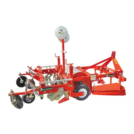
  • Seite 142: Technische Daten Der Mit Der Folienlegemaschine Kombinierten Dammhäufelmaschine (Al-S14 Plus)

    TECHNISCHE INFORMATIONEN Technische Daten der mit der Folienlegemaschine kombinierten Dammhäufelmaschine (AL-S14 PLUS) Die Maschine wurde entworfen und gebaut, um gleich- und die Mulchfolie zu verlegen. zeitig das erhöhte Saat- oder Pflanzbett vorzubereiten Hauptelemente (AL-S14 PLUS) UN41-0295LI A) Struktur für die Anbringung am Dreipunktanschluss...
  • Seite 143 TECHNISCHE INFORMATIONEN Abmessungen (AL-S14 PLUS) 3000 1650 UN41-0288II Technische Daten (AL-S14 PLUS) Abmessungen des Pflanzbettes oder Umpflanzen Erforderliche Leistung des Schleppers Maximale Breite des Dammes Reifendruck der Stützräder Druck der Reifen auf 0,5 ÷ 1 der Drückrädern auf die Folie...
  • Seite 144: Zulässiges Gefälle

    40054 - BUDRIO (BOLOGNA) - ITALIA UNI EN 13857 zur Maschinensicherheit. erklärt auf seine Verantwortung, dass die Maschinen Modell AL, Modell S14 PLUS und Modell AL-S14 PLUS Budrio den Wesentlichen Anforderungen an Sicherheit und Ge- sundheitsschutz gemäß der Richtlinie 2006/42/EG ent- CHECCHI &...
  • Seite 145: Warn- Und Hinweisschilder

    Die Abbildung zeigt die Position und die Bedeutung der Gefahr - Achtung angebrachten Schilder. Stellen Sie sicher, dass die Schilder leserlich sind; rei- nigen Sie sie anderenfalls oder bringen Sie neue in der Originalposition an. S14 PLUS AL-S14 PLUS UN41-0292II Deutsche Sprache Gebrauch und Wartung...
  • Seite 146: Sonderzubehör

    Sie den Zündschlüssel vor F) Hinweisschild: gibt die Anschlagpunkte an. jeglichen Eingriffen an der Arbeitsmaschine. Sonderzubehör Die Tabelle gibt die installierbaren Zubehörvorrichtungen an. AL-S14 PLUS PLUS Reihenzieher mit manueller Hebevorrichtung Vorrichtung zur Verlegung des Bewässerungsschlauchs Kit Schlauch-Eingraber Rolle für Drainageöffnungen in der Mulchfolie...
  • Seite 147: Informationen Zur Sicherheit

    INFORMATIONEN ZUR SICHERHEIT Allgemeine Sicherheitsvorschriften Wartung oder sonstigen Eingriffen an der Arbeits- Der Großteil der Unfälle und Verletzungen, die am maschine. Arbeitsplatz auftreten, werden durch die Nichtein- haltung einiger einfacher Regeln der Vorsicht und Lassen Sie Aufmerksamkeit walten und beachten Sie Sicherheit verursacht.
  • Seite 148 INFORMATIONEN ZUR SICHERHEIT Sicherheitsvorschriften zu Einstellung und Wartung Die Wartung ist ein Aspekt, der für die Funktions- nem und kompaktem Untergrund mit abgeschalte- tüchtigkeit und Zuverlässigkeit der Maschine von tem Schlepper, angezogener Feststellbremse und primärer Bedeutung ist; er verkörpert einen der abgezogenem Zündschlüssel ausgeführt werden.
  • Seite 149: Informationen Zur Bewegung Und Zur Installation

    Die Kollis können direkt auf das Transportmittel geladen Auf der Verpackung sind alle zum sicheren Be- und Ent- laden erforderlichen Informationen angegeben. Die Abbildung zeigt die am häufigsten verwendeten Verpackungsarten. S14 PLUS AL-S14 PLUS UN41-0296LI Deutsche Sprache Gebrauch und Wartung...
  • Seite 150: Bewegung Und Heben Der Verpackung

    Überprüfen Sie das Gewicht des Packstücks direkt und Vorsicht um, damit gefährliche Schwankungen ver- auf der Verpackung. mieden werden. Die Abbildung zeigt die Anschlagpunkte und die Vorge- hensweise beim Heben. S14 PLUS AL-S14 PLUS UN41-0299LI Deutsche Sprache Gebrauch und Wartung...
  • Seite 151: Auspacken

    3) Schlagen Sie die Maschine an und heben Sie sie. Achten Sie besonders darauf, die Sicherheit und Un- Die Arbeitsmaschine AL-S14 PLUS ist in zwei Teile versehrtheit der direkt in die Arbeitsgänge einbezo- geteilt auf Paletten verpackt, die angeschlagen und genen Personen zu schützen.
  • Seite 152 (C) blockiert ist und, dass die Ketten stabil richtung (A), die zusammen mit der Arbeitsmaschine am Rahmen (D) angebracht sind. geliefert wird. Die Abbildung zeigt die Anschlagpunkte und die Vorge- AL-S14 PLUS hensweise beim Heben des Modells AL-S14 PLUS. UN41-0306LI Deutsche Sprache Gebrauch und Wartung...
  • Seite 153: Informationen Zu Den Einstellungen

    Untergrund mit abgeschaltetem Schlepper, sämtliche Maßnahme angewendet werden, die zur angezogener Feststellbremse und abgezogenem Gewährleistung der Sicherheit erforderlich sind. Einstellen der Stützräder (AL) Die Stützräder dienen zur Bestimmung des Verdich- tungsgrades des Bodens. Gehen Sie zum Einstellen der Stützräder wie beschrie- ben vor.
  • Seite 154: Einstellungen Der Seitenteile Zur Formgebung

    INFORMATIONEN ZU DEN EINSTELLUNGEN Einstellungen der Seitenteile zur Formgebung Die kombinierte Einstellung der Seitenteile (quer und Stellen Sie die Seitenteile günstig ein, um den Damm auf senkrecht) bedingt die Breite und Höhe des Dammes. die gewünschte Weise herzustellen. Einstellen in Querrichtung __________________________________________________________________________ UN41-0338LI a) Breite des Dammes 3) Entfernen oder nähern Sie die Seitenteile in gleichem...
  • Seite 155: Einstellen Der Äußeren Förderpflugschare

    INFORMATIONEN ZU DEN EINSTELLUNGEN Einstellen der äußeren Förderpflugschare Stellen Sie die äußeren Förderpflugschare so ein, dass eine ausreichende Menge Erdreich in das Innere der Seitenteile zur Formgebung gelangen. Einstellen der Arbeitstiefe der äußeren Förderpflugschare_________________________________________________ 1) Lockern Sie die Schrauben (A) an beiden äußeren Förderpflugscharen.
  • Seite 156: Einstellen Der Inneren Förderpflugschare

    INFORMATIONEN ZU DEN EINSTELLUNGEN Einstellen der inneren Förderpflugschare Die inneren Förderpflugschare dienen zum Ansammeln einer größeren oder kleineren Menge Erdreich in der Mitte des Damms. UN41-0308LI Gehen Sie zum Einstellen der inneren Förderpflugschare - Heben oder senken Sie die Pflugschar, um die in die wie beschrieben vor.
  • Seite 157: Einstellen Der Anhäufelscheiben

    INFORMATIONEN ZU DEN EINSTELLUNGEN Die Furchenöffnerpflugschare dienen zum Herstellen - Verändern Sie die Neigung der Pflugschare, um die von Furchen im Erdreich, an denen die Ränder der Fo- Furchenbreite zu erhöhen oder zu verringern. lie verlegt werden. Sie sind hinsichtlich Breite, Tiefe und 3) Ziehen Sie die Schraube (A) an.
  • Seite 158 INFORMATIONEN ZU DEN EINSTELLUNGEN Einstellen des Drucks der Scheibe auf dem Erdreich_______________________________________________________ Gehen Sie zum Regeln des Drucks der Scheibe wie be- schrieben vor. 1) Drehen Sie das Handrad (H), um den Druck der Schei- be auf dem Boden zu erhöhen oder zu verringern. UN41-0365AL Regelung von Tiefe, Neigung und Längsverschiebung der Scheibe___________________________________________ Gehen Sie zum Einstellen der Scheibe wie beschrieben...
  • Seite 159: Einstellen Der Druckräder Auf Mulchenfolien

    INFORMATIONEN ZU DEN EINSTELLUNGEN Einstellen der Druckräder auf Mulchenfolien Die Druckräder dienen dazu, die Folie auf dem Erdreich gespannt zu halten. Einstellen der Entfernung der Druckräder zum Folienrand ________________________________________________ UN41-0315LI 1 - Mulchfolienrolle 3 - Saat- oder Pflanzbett (Damm) 2 - Auf dem Damm verlegte Mulchfolie 4 - Druckrad Gehen Sie zum Einstellen der Druckräder wie beschrieben vor.
  • Seite 160: Einstellen Der Halterung Für Die Rolle - Folienvorgelegerolle

    INFORMATIONEN ZU DEN EINSTELLUNGEN Einstellen des Radsturzes____________________________________________________________________________ Verändern Sie den Radsturz, um kleine Verschiebungen des Reifens vom Folienrand vorzunehmen. Gehen Sie zum Einstellen des Radsturzes wie beschrie- ben vor. 1) Lösen Sie die Schrauben (A). 2) Verändern Sie die Neigung des Rades je nach Bedarf. 3) Ziehen Sie die Schrauben (A) an.
  • Seite 161: Einstellen Der Folienabwickelspannung

    INFORMATIONEN ZU DEN EINSTELLUNGEN Einstellen der Folienabwickelspannung Gehen Sie zum Einstellen der Folienabwickelspannung wie beschrieben vor. 1) Senken Sie die Rollenbremse, um die Spannung der Feder aufzuheben. 2) Lösen Sie die Feder (A) aus der Spannvorrichtung (B) und fügen Sie sie in eine der vorgesehenen Öffnun- gen ein.
  • Seite 162: Informationen Zur Benutzung

    INFORMATIONEN ZUR BENUTZUNG Sicherheitsempfehlungen für den Gebrauch Lesen Sie, um Unfallgefahren vorzubeugen, sorgfäl- einzuleiten, um diese Gefahren zu beseitigen oder tig die Sicherheitshinweise im Kapitel “3”. zu verringern. Gestatten Sie die Benutzung der Maschine aus- Stellen Sie sicher, dass sich keine Personen oder Tie- schließlich dazu befugtem Personal mit gutem Ge- ren im Manöver- und Arbeitsbereich der Maschine sundheitszustand, angemessener Ausbildung sowie...
  • Seite 163: Vorgehensweise Zum Herstellen Des Damms

    INFORMATIONEN ZUR BENUTZUNG UN41-0318LI 6) Stecken Sie die Bolzen (C) in die Hubarme und setzen Gehen Sie beim Ablösen wie beschrieben vor _________ Sie die Sicherungsstifte ein (D). 1) Wählen Sie einen ebenen und festen Bereich für das 7) Drehen Sie die Zugstange (E), um den Abstand der Parken der Arbeitsmaschine - den Schlepper.
  • Seite 164: Vorgehensweise Zum Verlegen Der Folie

    INFORMATIONEN ZUR BENUTZUNG Vorgehensweise zum Verlegen der Folie Das Verlegen der Folie muss auf entspre- chend mit Egge oder Hackmaschine vorbe- reitetem Erdreich erfolgen, das ausreichend zerkleinert und eingeebnet wurde. Legen Sie die Folie nicht auf zu nassem Erd- reich aus. Gehen Sie zum Verlegen der Folie auf dem Erdreich wie beschrieben vor.
  • Seite 165: Vorgehensweise Zum Herstellen Des Damms Und Gleichzeitigen Verlegung Der Mulchfolie

    INFORMATIONEN ZUR BENUTZUNG Vorgehensweise zum Herstellen des Damms und gleichzeitigen Verlegung der Mulchfolie UN41-0339LI Das Herstellen des Damms und die gleichzeitige Verle- Stellen Sie die Position der Drückräder ein (siehe gung der Mulchfolie müssen auf einem entsprechend unter “Einstellen der Druckräder auf Mulchenfoli- mit Glättegge oder Hackmaschine vorbereiteten, ausrei- en”).
  • Seite 166: Laden Der Mulchfolienrolle

    INFORMATIONEN ZUR BENUTZUNG Laden der Mulchfolienrolle 2,5 mm 2,5 mm UN41-0325LI Gehen Sie zum Laden der Mulchfolienrolle wie beschrie- schine. ben vor. 5) Nähern Sie die Scheiben (B) unter Einhaltung des in der Abbildung angegebenen Abstandes der Rolle. 1) Lösen Sie die Schrauben (A). 6) Ziehen Sie die Schrauben (A) an.
  • Seite 167 INFORMATIONEN ZUR BENUTZUNG Transport der Arbeitsmaschine_______________________________________________________________________ Gehen Sie zum Laden der Arbeitsmaschine auf das Trans- portmittel wie beschrieben vor. 1) Schlagen Sie die Maschine an den vom Hersteller vorgesehenen Anschlagstellen an. - Nehmen Sie für die Anschlagstellen und die Vorge- hensweise zum Heben auf den Abschnitt “Heben der Arbeitsmaschine”...
  • Seite 168: Fahrt Auf Öffentlichen Straßen

    INFORMATIONEN ZUR BENUTZUNG Fahrt auf öffentlichen Straßen Gefahr - Achtung Gefahr - Achtung Es ist untersagt, Personen und/oder Sachen auf der Entfernen Sie vor dem Befahren der Straße die even- Arbeitsmaschine zu transportieren. tuelle Mulchfolienrolle von der Arbeitsmaschine und säubern Sie die Reifen sowie die Bauteile von Er- drückständen.
  • Seite 169: Informationen Zur Wartung

    INFORMATIONEN ZUR WARTUNG Sicherheitsempfehlungen zur Wartung Die Wartungseingriffe müssen auf ebenem und kom- sungshandbuch beschrieben werden, können im Un- paktem Untergrund mit abgeschaltetem Schlepper, ternehmen durchgeführt werden. angezogener Feststellbremse und abgezogenem Für außerordentliche Eingriffe (die im vorliegenden Zündschlüssel ausgeführt werden; dabei müssen Handbuch nicht behandelt werden) ist eine Werk- sämtliche Maßnahme angewendet werden, die zur statt erforderlich, die den Bestimmungen der gel-...
  • Seite 170: Reinigung Der Arbeitsmaschine

    Halterung für die Rolle - Folienvorgelegerolle” Die Stützräder sind nicht richtig Stellen Sie die Stützräder ein Siehe “Einstellen der Stützräder eingestellt (AL)” oder “Einstellen der Stützräder (S 14 PLUS)” Die Abwickelspannung der Rolle Stellen Sie die Abwickelspannung Siehe unter “Einstellen der ist falsch der Rolle ein Folienabwickelspannung”...
  • Seite 171: Plan Der Schmierungspunkte

    INFORMATIONEN ZUR WARTUNG Plan der Schmierungspunkte Schmieren Sie die abgebildeten Organe unter Beach- des verteilten Schmiermittels zu vermeiden. tung der angegebenen Zeiten und Modalitäten. Verwenden Sie wasserabstoßendes Universalfett mit Reinigen Sie vor dem Schmieren sorgfältig die betroffe- einem Tropfpunkt von 180° für Landwirtschafts- und In- nen Bauteile und Fettbüchsen, um eine Verschmutzung dustriemaschinen.
  • Seite 172: Verschrottung Der Arbeitsmaschine

    INFORMATIONEN ZUR WARTUNG Verschrottung der Arbeitsmaschine Leiten Sie geeignete Sicherheitsmaßnahmen ein, um die Art des Materials trennen, aus denen sie bestehen. Da- Unversehrtheit der direkt in die Verschrottungsarbeiten nach erfolgt die getrennte Entsorgung unter Einhaltung einbezogenen Personen zu garantieren. der diesbezüglich geltenden Gesetze. Lassen Sie keine nicht biologisch abbaubaren Produkte, Die mit der Verschrottung der Arbeitsmaschine beauf- wie Schmiermittel und nicht eisenhaltige Bauteile (Gum-...
  • Seite 173 ANLAGEN Sonderzubehör In diesem Kapitel werden die Montage und die Funkti- onsweise einiger Zubehörteile beschrieben, die auch Gefahr - Achtung nach der Übergabe der Arbeitsmaschine lieferbar sind. Die Aus- und Einbauarbeiten müssen mit geeigneten Lesen Sie zum Schutz der Sicherheit der Personen die im Werkzeugen und durch zugelassenes Personal vor- Kapitel “3”...
  • Seite 174: Eingraber Für Bewässerungsschlauch

    ANLAGEN Eingraber für Bewässerungsschlauch Der Eingraber dient dazu, eine Vertiefung im Erdreich zu schaffen und darin den Bewässerungsschlauch zu verlegen. UN41-0335-FM Montage des Eingrabers__________________________ Einstellen des Eingrabers__________________________ 1) Positionieren Sie den Eingraber auf der Arbeitsma- Gehen Sie zum Einstellen des Eingrabers wie beschrie- schine.
  • Seite 175 ANLAGEN Umbau der Arbeitsmaschine AL-S14 PLUS _____________________________________________________________ Die Arbeitsmaschine kann mit dem Zweck umgebaut enlegemaschine durch das Umbauset ergänzt wird. werden, den Damm zu erstellen sowie die Mulchfolie Das Umbauset muss direkt beim Hersteller oder bei vom unabhängig davon zu verlegen.
  • Seite 176 ANLAGEN Gehen Sie zur Montage des Umbausets wie beschrieben vor. 1) Montieren Sie das Set der Befestigungsvorrichtung am dritten Punkt des Traktors, wie in der Abbildung angegeben. UN41-0333-LI 2) Positionieren Sie in der Mitte des Rahmen die Vorrich- tung zum Anschluss an den Dritpunkt des Traktors. 3) Montieren Sie die Bügel (A, B, C).
  • Seite 177 ANLAGEN Umbau der getrennten Arbeitsmaschinen AL und S14 PLUS________________________________________________ Die Arbeitsmaschinen können mit dem Zweck umge- Der Umbau besteht darin, die Dammhäufelmaschine mit baut werden, gleichzeitig den Damm herzustellen sowie der Folienlegemaschine zu verbinden sowie die Union die Mulchfolie zu verlegen.
  • Seite 178 ANLAGEN 10) Starten Sie die Arbeitsmaschinen. 11) Schieben Sie die Böcke (B) in die Bohrungen der Platte am Gestell der Dammhäufelmaschine. 12) Ziehen Sie die Muttern (A) an. UN41-0328-LI 13) Schieben Sie die Böcke (D) in die Bohrungen der Platte am Gestell der Dammhäufelmaschine. 14) Ziehen Sie die Muttern (C) an.
  • Seite 179 Carga de la bobina de película protectora .................... 30 Circulación por carreteras ........................... 32 Conexión y desconexión de la máquina operadora al tractor ............26 Control de los neumáticos .......................... 33 Datos identificativos del fabricante y de la máquina ................1 Declaración de conformidad.........................8...
  • Seite 180 Recomendaciones sobre seguridad durante el desplazamiento y el transporte ....13 Regulación de las rejas desaporcadoras ....................20 Regulación de las ruedas de apoyo (AL) ....................17 Regulación de las ruedas de apoyo (S14 PLUS) ................... 17 Regulación de las ruedas de presión sobre la película protectora ..........23 Regulación de la tensión de desenrollado de la película ..............
  • Seite 181 INFORMACIONES DE CARACTER GENERAL Objeto del manual El manual ha sido realizado por el fabricante para pro- En caso de duda solicitar aclaraciones al fabricante o a porcionar las informaciones necesarias y los criterios a los centros de asistencia autorizados.
  • Seite 182: Exclusión De Responsabilidad

    - el uso de recambios no originales o que no sean espe- - Cualquier modificación no autorizada por el fabrican- cíficos para el modelo provocará la invalidación de la garantía y eximirá al fabri- - el uso impropio de la máquina operadora cante de toda responsabilidad por lesiones a personas o - el uso de la máquina operadora de parte del personal...
  • Seite 183: Descripción General

    Modelos de máquinas operadoras. - AL: preparadora para la formación y la compactación El fabricante ha previsto la instalación de unidades adi- del lecho realzado de siembra y de trasplante (tabla de cionales y accesorios que modifican y optimizan las fun- siembra).
  • Seite 184 INFORMACIONES TECNICAS Dimensiones lecho de siembra o de trasplante con Datos técnicos (AL) cumbrera inclinada Potencia de tracción requerida cm 45 ÷ 86 Anchura de trabajo máxima Presión neumáticos Peso total de la máquina operadora Dimensiones del lecho de siembra o de trasplante...
  • Seite 185 INFORMACIONES TECNICAS Dimensiones (S14 PLUS) 1850 1650 UN41-0287II Datos técnicos (S14 PLUS) Potencia de tracción requerida Anchura de trabajo máxima Presión neumáticos ruedas de apoyo Presión de los neumáticos de 0,5 ÷ 1 las ruedas de presión sobre la película Peso total de la máquina operadora (sin bobinas) Diámetro máximo de la bobina Anchura máxima de la bobina...
  • Seite 186 INFORMACIONES TECNICAS Características técnicas preparadora combinada con la cubridora (AL-S14 PLUS) La máquina ha sido diseñada y fabricada para efectuar para la siembra y/o trasplante y la colocación de la pelí- de modo simultáneo la preparación del lecho realzado cula protectora.
  • Seite 187 INFORMACIONES TECNICAS Dimensiones (AL-S14 PLUS) 3000 1650 UN41-0288II Datos técnicos (AL-S14 PLUS) Dimensiones del lecho de siembra o de trasplante Potencia de tracción requerida Anchura máxima de la tabla de siembra Presión neumáticos ruedas de apoyo Presión de los neumáticos de las 0,5 ÷...
  • Seite 188: Declaración De Conformidad

    40054 - BUDRIO (BOLOGNA) - ITALIA 13857 relativas a la seguridad de la maquinaria. declara bajo su propia responsabilidad que las máqui- nas modelo AL, modelo S14 PLUS y modelo AL-S14 Budrio PLUS cumplen con los Requisitos Esenciales de Seguri- dad y Protección de la Salud establecidos en la Directiva...
  • Seite 189: Señales De Seguridad E Información

    Peligro - Atención placas aplicadas. Controlar que las placas estén legibles; en caso con- trario limpiarlas y, de estar dañadas, sustituirlas con placas nuevas a aplicar en las mismas posiciones ori- ginales. S14 PLUS AL-S14 PLUS UN41-0292II Lengua español Uso y mantenimiento...
  • Seite 190 Ruido El empleo de las máquinas no comporta un aumento Consultar el manual del fabricante del tractor para esta- significativo del nivel de presión sonora del tractor al blecer cuáles son los dispositivos de protección indivi- cual son conectadas. dual que se han de adoptar para proteger los oídos.
  • Seite 191: Informaciones Sobre La Seguridad

    Normas de seguridad sobre el uso y el funcionamiento Controlar que el acoplamiento de la máquina opera- A fin de reducir al mínimo los riesgos de accidente, dora al tercer punto de conexión del tractor quede la conducción del tractor debe ser encargada sólo a...
  • Seite 192 Las intervenciones de mantenimiento y regulación de escasa seguridad.
  • Seite 193 La ilustración muestra los tipos de embalaje mayormen- te utilizados. S14 PLUS AL-S14 PLUS UN41-0296LI Lengua español Uso y mantenimiento...
  • Seite 194 Controlar el peso de cada fardo indicado directamen- dencia, para evitar peligrosas oscilaciones. te en el embalaje. En la ilustración se indican los puntos de fijación y la mo- dalidad de elevación. S14 PLUS AL-S14 PLUS UN41-0299LI Lengua español Uso y mantenimiento...
  • Seite 195 Efectuar el desembalaje sobre una superficie sólida y se- de daños, comunicar el hecho al revendedor o directa- gura. mente al fabricante dentro de los ocho días sucesivos a El personal encargado de desplazar la carga debe poseer la recepción de la máquina.
  • Seite 196 (C) y que las cadenas estén esta- silio (A) suministrado adjunto a la máquina operado- blemente enganchadas en el chasis (D). La ilustración presenta los puntos de amarre y la modali- AL-S14 PLUS dad de elevación del modelo AL-S14 PLUS. UN41-0306LI Lengua español Uso y mantenimiento...
  • Seite 197 Regulación de las ruedas de apoyo (AL) Las ruedas de apoyo sirven para determinar el grado de compactación del terreno.
  • Seite 198 INFORMACIONES SOBRE LAS REGULACIONES Regulaciones de partes laterales formadoras La regulación combinada de las partes laterales (trans- Regular convenientemente las partes laterales a fin de versal y vertical) determina la anchura y la altura de la realizar la tabla de la manera requerida. tabla.
  • Seite 199 INFORMACIONES SOBRE LAS REGULACIONES Regulación rejas conductoras externas Regular las rejas conductoras externas de modo que permitan conducir la suficiente cantidad de terreno al interior de las partes laterales formadoras. Regulación de la profundidad de trabajo de las rejas conductoras externas___________________________________ 1) Aflojar los tornillos (A) en ambas rejas conductoras externas.
  • Seite 200 INFORMACIONES SOBRE LAS REGULACIONES Regulación rejas conductoras internas Las rejas conductoras internas sirven para acumular una mayor o una menor cantidad de terreno en el centro de la tabla. UN41-0308LI Para regular las rejas conductoras internas proceder de - Alzar o bajar la reja para aumentar o disminuir la can- la siguiente forma.
  • Seite 201 INFORMACIONES SOBRE LAS REGULACIONES Las rejas desaporcadoras se utilizan para efectuar los - Variar la inclinación de las rejas para aumentar o dis- surcos en el terreno en que se colocarán los bordes de minuir la anchura del surco. la película y pueden ser reguladas en anchura, profundi- 3) Enroscar el tornillo (A).
  • Seite 202 INFORMACIONES SOBRE LAS REGULACIONES Regulación de la presión del disco sobre el terreno_______________________________________________________ Para regular la presión del disco proceder de la manera indicada. 1) Girar el volante (H) para aumentar o disminuir la pre- sión del disco sobre el terreno. UN41-0365AL Regulación de la profundidad, de la inclinación y del desplazamiento longitudinal del disco_____________________ Para regular el disco proceder de la manera indicada.
  • Seite 203 INFORMACIONES SOBRE LAS REGULACIONES Regulación de las ruedas de presión sobre la película protectora Las ruedas de presión mantienen tensada la película sobre el terreno. Regulación de la distancia de las ruedas de presión respecto del borde de la película ___________________________ UN41-0315LI 1 - Bobina de película protectora 3 - Lecho de siembra o de trasplante (tabla de siembra)
  • Seite 204 3) Sostener adecuadamente el soporte para evitar que pueda caer al suelo y causar un accidente. 4) Desenroscar los pernos (B) por ambos lados de la máquina. 5) Alzar o bajar el soporte de la manera requerida y ali- near los agujeros próximos del soporte respecto de...
  • Seite 205 INFORMACIONES SOBRE LAS REGULACIONES Regulación de la tensión de desenrollado de la película Para regular la tensión de desenrollado de la película proceder de la manera indicada. 1) Bajar el freno bobina para descargar la tensión del resorte. 2) Desenganchar el resorte (A) del dispositivo de tensa- do (B) e introducirlo en uno de los agujeros previstos para ello.
  • Seite 206: Informaciones Sobre El Uso

    Controlar que el acoplamiento de la máquina opera- dora al tercer punto de conexión del tractor quede blo- queado de manera que no pueda desengancharse. UN41-0318LI Para efectuar este acoplamiento proceder de la manera indicada___________________________________________ 1) Posicionar la máquina operadora sobre terreno sóli-...
  • Seite 207 9) Regular el tirante (E) de manera que la máquina ope- 3) Apagar el motor del tractor y extraer la llave del en- radora quede paralela al terreno. cendido desde el salpicadero. 4) Retirar la clavija de seguridad (H) y extraer el perno (G).
  • Seite 208 Para extender la película sobre el terreno, proceder de la manera indicada. Posicionar la máquina longitudinalmen- te al tramo de terreno que se ha de recu- brir con la película. Regular la posición de las rejas desapor- cadoras (véase “Regulación de las rejas desaporcadoras”).
  • Seite 209 17) Al concluir la colocación de la película sobre la ta- bla (véase “Regulación rejas conductoras internas”). bla, detener la máquina operadora y cortar la pelí- Regular las ruedas de apoyo para determinar la co- cula antes de comenzar una nueva tabla.
  • Seite 210 Peligro - Atención Peligro - Atención Para cargar y descargar la máquina operadora utili- Proceder con máxima cautela al ejecutar las opera- zar medios de elevación de capacidad adecuada con- ciones de elevación para evitar daños a la máquina siderando el peso que se debe elevar.
  • Seite 211 1) Subir al medio de transporte de la manera indicada en la figura y a velocidad mínima. 2) Hacer descender la máquina sobre la plataforma del Peligro - Atención...
  • Seite 212 Es obligatorio bloquear la conexión de tres puntos me- del control del vehículo. Inactividad prolongada de la máquina operadora Al preverse un largo período de inactividad de la má- 5) Engrasar los componentes sujetos a lubricación (ver quina operadora, se deberá aplicar el siguiente procedi- “Esquema puntos de lubricación”).
  • Seite 213: Informaciones Sobre El Mantenimiento

    INFORMACIONES SOBRE EL MANTENIMIENTO Recomendaciones de seguridad para el mantenimiento Las intervenciones de mantenimiento deben efec- aquellas del mantenimiento ordinario indicadas en tuarse sobre terreno plano y compacto, con el motor el manual de instrucciones. del tractor apagado, el freno de estacionamiento Para efectuar intervenciones extraordinarias (no aplicado, la llave de encendido extraída y adoptando señaladas en este manual), se debe disponer de un...
  • Seite 214: Inconvenientes, Causas Y Remedios

    Las ruedas de apoyo no están Regular las ruedas de apoyo Véase “Regulación de la ruedas correctamente reguladas de apoyo (AL)” o “Regulación de la ruedas de apoyo (S 14 PLUS)” La tensión de desenrollado de la Regular la tensión de Véase “Regulación de la tensión...
  • Seite 215 INFORMACIONES SOBRE EL MANTENIMIENTO Esquema puntos de lubricación Lubricar los órganos ilustrados según frecuencias y con se contamine el lubricante utilizado. modalidades indicadas. Usar grasa universal para vehículos y maquinarias agrí- Antes de lubricar, limpiar cuidadosamente los respecti- colas e industriales, hidrorrepelente y con punto de go- vos componentes y los engrasadores a fin de evitar que teo a 180°.
  • Seite 216 INFORMACIONES SOBRE EL MANTENIMIENTO Desguace de la máquina operadora Predisponer adecuadas medidas de seguridad para sal- eliminación/reciclaje diferenciado procediendo en con- vaguardar la incolumidad de las personas directamente formidad con lo establecido por las normas vigentes en involucradas en las operaciones de desguace. la materia.
  • Seite 217: Accesorios Opcionales

    ANEXOS Accesorios opcionales En este capítulo se describen el montaje y las funcio- nalidades de algunos accesorios que pueden ser sumi- Peligro - Atención nistrados con posterioridad a la entrega de la máquina Las operaciones de desmontaje y montaje deben ser operadora.
  • Seite 218 ANEXOS Enterrador de la manguera de irrigación El enterrador se utiliza para realizar una excavación en el terreno y colocar dentro del surco la manguera de irriga- ción. UN41-0335-FM Montaje del enterrador___________________________ Regulación del enterrador_________________________ 1) Posicionar el enterrador en la máquina operadora. Para regular el enterrador proceder de la manera indi- 2) Montar las abrazaderas (A).
  • Seite 219 La máquina operadora puede ser reconvertida a fin de El kit de transformación debe ser solicitado directamen- ejecutar la tabla de siembra y la colocación de la película te al fabricante o a las organizaciones autorizadas por el protectora por separado. fabricante (talleres, puntos de venta, etc.).
  • Seite 220 ANEXOS Para montar el kit de transformación proceder de la si- guiente forma. 1) Ensamblar el kit de la estructura de conexión al terce- ro punto del tractor procediendo de la manera indi- cada en la figura. UN41-0333-LI 2) Colocar en el centro del chasis la estructura de co- nexión al tercer punto del tractor.
  • Seite 221 ANEXOS Transformación de las máquinas operadoras AL y S14 PLUS separadas_______________________________________ Las máquinas operadoras pueden ser reconvertidas a La reconversión consiste en unir la preparadora a la cu- fin de ejecutar la tabla y aplicar la película protectora de bridora y completar la unión con el respectivo kit de modo simultáneo.
  • Seite 222 ANEXOS 10) Aproximar las máquinas operadoras. 11) Introducir las horquillas (B) en los agujeros de la placa en el chasis de la preparadora. 12) Enroscar las tuercas (A). UN41-0328-LI 13) Introducir las horquillas (D) en los agujeros de la placa en el chasis de la preparadora. 14) Enroscar las tuercas (C).
  • Seite 224 VIA GUIZZARDI, 38 40054 BUDRIO (BO) - ITALY TEL. (051) 80.02.53 - FAX (051) 69.20.611 www.checchiemagli.com info@checchiemagli.com...

Diese Anleitung auch für:

S14 plusAl-s14 plus

Inhaltsverzeichnis