Herunterladen Inhalt Inhalt Diese Seite drucken
Lenze EMF2133IB Montageanleitung
Vorschau ausblenden Andere Handbücher für EMF2133IB:
Inhaltsverzeichnis

Werbung

Verfügbare Sprachen

Verfügbare Sprachen

EDKMF2133
.ñTB
PROFIBUS
EMF2133IB
Kommunikationsmodul
Communication module
Module de communication
Montageanleitung
Mounting Instructions
Instructions de montage

Werbung

Inhaltsverzeichnis
loading

Inhaltszusammenfassung für Lenze EMF2133IB

  • Seite 1 EDKMF2133 .ñTB Montageanleitung Mounting Instructions Instructions de montage PROFIBUS EMF2133IB Kommunikationsmodul Communication module Module de communication ...
  • Seite 2  Lesen Sie zuerst diese Anleitung und die Dokumentation zum Grundgerät, bevor Sie mit den Arbeiten beginnen! Beachten Sie die enthaltenen Sicherheitshinweise.  Please read these instructions and the documentation of the basic device before you start working! Observe the safety instructions given therein! ...
  • Seite 3 EMF2133IB PROFIBUS DP 2131 24V DC 2133 2133PFB003 2102LEC007...
  • Seite 4 Steckerleiste mit Schraubanschluss, 2-polig  16 PE-Anschluss (nur bei 82XX) Hinweis  unten Befestigungsschraube  Typenschild  5  Tipp! Aktuelle Dokumentationen und Software-Updates zu Lenze Produkten finden Sie im Internet jeweils im Bereich ”Services & Downloads” unter http://www.Lenze.com  EDKMF2133 DE/EN/FR 4.0...
  • Seite 5: Gültigkeit

    Gültigkeit Diese Anleitung ist gültig für ƒ Kommunikationsmodule EMF2133IB (PROFIBUS) ab Version Vx. 0x. Diese Anleitung ist nur gültig zusammen mit der zugehörigen Betriebsanleitung der für den Einsatz zulässigen Grundgeräte. Identifikation 1D74 Type Id.-No. Prod.-No. Ser.-No. Input  E82AF000P0B201XX 99371BC019 ...
  • Seite 6 Einsetzbarkeit Das Kommunikationsmodul ist einsetzbar in Verbindung mit Grundgeräten ab folgenden Typenschildbezeichnungen: Version Gerätetyp Ausführung Variante Erläuterung 33.820X E./C. Vxxx 8201 - 8204 33.821X E./C. Vxxx 8211 - 8218 33.822X Vxxx 8221 - 8227 33.824X E./C. Vxxx 8241 - 8246 82EVxxxxxBxxxXX 8200 vector 82CVxxxxxBxxxXX...
  • Seite 7: Inhaltsverzeichnis

    Inhalt Sicherheitshinweise ..........Definition der verwendeten Hinweise .
  • Seite 8: Sicherheitshinweise

    Sicherheitshinweise Definition der verwendeten Hinweise Sicherheitshinweise Definition der verwendeten Hinweise Um auf Gefahren und wichtige Informationen hinzuweisen, werden in dieser Dokumenta- tion folgende Piktogramme und Signalwörter verwendet: Sicherheitshinweise Aufbau der Sicherheitshinweise:  Gefahr! (kennzeichnet die Art und die Schwere der Gefahr) Hinweistext (beschreibt die Gefahr und gibt Hinweise, wie sie vermieden werden kann) Piktogramm und Signalwort...
  • Seite 9: Restgefahren

    Sicherheitshinweise Restgefahren Restgefahren  Gefahr! Beachten Sie die in den Anleitungen zum Grundgerät enthaltenen Sicherheitshinweise und Restgefahren.  EDKMF2133 DE/EN/FR 4.0...
  • Seite 10: Lieferumfang

    Lieferumfang Lieferumfang  EMF2133IB PROFIBUS DP 2131 24V DC 2133 2133PFB003, E82ZAFX021/25 Lieferumfang siehe Kommunikationsmodul 2133 Montageanleitung Steckerleiste mit Schraubanschluss, 2-polig  16  Tipp! Ergänzend zu dieser Montageanleitung stellen wir unter der auf Seite 4 angegebenen Internetadresse weitergehende Informationen zu diesem Kommunikationsmodul zur Verfügung.
  • Seite 11: Mechanische Installation

    Mechanische Installation Mechanische Installation 2102LEC014 ƒ Stecken Sie das Kommunikationsmodul auf das Grundgerät (hier: 8200 vector). ƒ Schrauben Sie das Kommunikationsmodul mit der Befestigungsschraube auf dem Grundgerät fest, um eine gute PE-Verbindung sicher zu stellen.  Hinweis! Zur internen Versorgung des Kommunikationsmoduls durch den Frequenzumrichter 8200 vector muss der Jumper in der Schnittstellenöffnung (siehe Abb.
  • Seite 12: Elektrische Installation

    1200 m E82ZAFP005 Abb. 1 Beispiel: PROFIBUS mit RS485-Verkabelung (ohne Repeater) Element Bemerkung Leitrechner z.B. PC oder SPS mit PROFIBUS-Master-Anschaltbaugruppe Buskabel Übertragungsrate an die Länge des Buskabels anpassen PROFIBUS-Slave Einsetzbares Grundgerät (GG, siehe 6) mit Kommunikationsmodul EMF2133IB  EDKMF2133 DE/EN/FR 4.0...
  • Seite 13: Emv-Gerechte Verdrahtung

    Elektrische Installation EMV-gerechte Verdrahtung EMV-gerechte Verdrahtung Für eine EMV-gerechte Verdrahtung beachten Sie bitte folgende Punkte:  Hinweis! Bei den Antriebsreglern 820X und 821X können elektromagnetische ƒ Einstrahlungen die Kommunikation beeinträchtigen. Eine sichere Kommunikation wird durch ein zusätzliches Kabel zwischen dem PE-Anschluss des Grundgerätes und dem PE-Anschluss des Kommunikationsmoduls ermöglicht.
  • Seite 14: Verdrahtung

    Elektrische Installation Verdrahtung Verdrahtung ƒ Nur Kabel verwenden, die den aufgeführten Spezifikationen entsprechen, siehe (14). ƒ Mit dem Busanschluss-Stecker die Verbindung zu den Antriebsreglern herstellen. Das Bussystem wird nicht unterbrochen, wenn der Busanschluss-Stecker vom Antriebsregler abgezogen wird. ƒ Hinweise und Verdrahtungsvorschriften in den Unterlagen zum Steuerungssystem beachten.
  • Seite 15 Elektrische Installation Verdrahtung Teilnehmer-Anzahl 2133PFB004 Segment Master (M) Slave (S) Repeater (R)  Tipp! Repeater besitzen keine Geräteadresse. Bei der Berechnung der maximalen Teilnehmeranzahl reduzieren sie aber auf jeder Segmentseite die Teilnehmeranzahl um 1. Mit Repeatern können Linien- und Baumtopologien aufgebaut werden. Die maximale Gesamtausdehnung des Bussystems hängt dabei ab von der verwendeten Übertragungsrate ƒ...
  • Seite 16: Spannungsversorgung

    Elektrische Installation Spannungsversorgung Spannungsversorgung Externe Spannungsversorgung  Hinweis! Bei externer Spannungsversorgung des Kommunikationsmoduls wird der aktive Busabschluss-Widerstand unabhängig vom Betrieb des Grundgerätes gespeist. Das Bussystem bleibt dadurch auch dann weiter aktiv, wenn das Grundgerät abgeschaltet wird oder ausfallen sollte. Versorgen Sie bei Bedarf das Kommunikationsmodul über die zweipolige Steckerleiste mit einer separaten Versorgungsspannung.
  • Seite 17 Elektrische Installation Spannungsversorgung Interne DC-Spannungsversorgung  Hinweis! Die Möglichkeit der internen Spannungsversorgung ist bei Grundgeräten mit erweiterter AIF-Schnittstellenöffnung (Frontseite 8200 vector) gegeben. Die in der Grafik grau hervorgehobene Fläche kennzeichnet die Jumperposition. Im Auslieferungszustand des Frequenzumrichters werden diese nicht ƒ intern versorgt.
  • Seite 18: Belegung Der Sub-D-Buchse

    Elektrische Installation Belegung der Sub-D-Buchse Belegung der Sub-D-Buchse Ansicht Bezeichnung Erläuterung RxD/TxD-P Datenleitung-B (Empfangs- / Sendedaten-Plus) Request To Send (Empfangs- / Sendedaten, kein Differenzsignal) M5V2 Datenbezugspotential (Masse zu 5V) P5V2 5 V DC / 30 mA (Busabschluss) RxD/TxD-N Datenleitung-A (Empfangs- / Sendedaten-Minus) ...
  • Seite 19: Inbetriebnahme

    Inbetriebnahme Vor dem ersten Einschalten Inbetriebnahme Vor dem ersten Einschalten  Stop! Überprüfen Sie vor dem Einschalten der Netzspannung die gesamte Verdrahtung auf Vollständigkeit, Kurzschluss und Erdschluss.  Hinweis! Für die Übertragungsrate sind keine manuellen Einstellungen erforderlich. Das Kommunikationsmodul stellt sich automatisch auf die Übertragungsrate des Masters ein.
  • Seite 20: Erstes Einschalten

    Software-Kompatibilität zum Kommunikationsmodul herstellen 25 2133: Schalter S8 = OFF 2131: Schalter S8 = ON (Fahren Sie bei dieser Einstellung mit der Inbetriebnahme zum Kommunikationsmodul 2131 fort) Lenze-Einstellung: S8 = OFF Antriebsspezifische Einstellungen vornehmen Dokumentation des Antriebsreg- lers Grundgerät zur Kommunikation vorbereiten 22...
  • Seite 21 Inbetriebnahme Erstes Einschalten Schritt Vorgehensweise siehe Adressierung der Busteilnehmer 28 Jeder Busteilnehmer benötigt eine andere Adresse. Sie können jetzt mit dem Antriebsregler kommunizieren, d.h. Prozessdaten (Soll- und Istwerte) austauschen alle Codestellen lesen alle beschreibbaren Codes verändern. Siehe Attributtabelle bzw. Codestellenbeschreibung des jeweiligen Grundgerätes.
  • Seite 22: Grundgerät Zur Kommunikation Vorbereiten

    Vorgehensweise siehe Damit Sie den Antriebsregler über PROFIBUS freigeben können, stellen Sie 10 den Lenze-Parameter Bedienungsart (C0001) von 0 auf 3. Dies können Sie mit dem Keypad EMZ9371BC oder direkt über PROFIBUS vornehmen. Beispiele für PROFIBUS Write (C0001=3): 10 – Index = 0x5FFE 10...
  • Seite 23 Vorgehensweise siehe Damit Sie den Antriebsregler über PROFIBUS steuern können, stellen Sie den Lenze-Parameter Signalkonfiguration (C0005) auf einen Wert xxx3. Dies können Sie mit dem Keypad EMZ9371BC oder direkt über PROFIBUS vornehmen. Für eine erste Inbetriebnahme sollten Sie die Signalkonfigura- tion 1013 (Drehzahlregelung) wählen.
  • Seite 24 Servosystem ECS, Varianten ”Speed & Torque” und ”Posi & Shaft” 1. Damit Sie den Antriebsregler über PROFIBUS steuern können, stellen Sie den Lenze-Parameter Signalkonfiguration (C0005) mit dem Keypad EMZ9371BC oder direkt über PROFIBUS auf einen Wert, der die Kommunikation über die AIF-Schnittstelle realisiert: ƒ...
  • Seite 25 Inbetriebnahme Grundgerät zur Kommunikation vorbereiten Software-Kompatibilität einstellen  Hinweis! Wenn Sie das Kommunikationsmodul EMF2131IB durch das Kommunikationsmodul EMF2133IB ersetzen, ändern Sie keine Einstellungen am Leitsystem ƒ setzen Sie den Schalter S8 auf Position ”ON” ƒ  EDKMF2133 DE/EN/FR 4.0...
  • Seite 26: Leitsystem Konfigurieren

    Inbetriebnahme Leitsystem konfigurieren Leitsystem konfigurieren Zur Kommunikation mit der Kommunikationsbaugruppe muss zunächst das Leitsystem konfiguriert werden. Einstellungen am Master Zur Projektierung des PROFIBUS muss im Master die Gerätestammdatendatei der Kommu- nikationsbaugruppe eingelesen werden.  EDKMF2133 DE/EN/FR 4.0...
  • Seite 27: Busabschluss-Widerstand Aktivieren

    Inbetriebnahme Busabschluss-Widerstand aktivieren Busabschluss-Widerstand aktivieren Nur beim ersten und letzten physikalischen Busteilnehmer ist ein Busabschluss-Wider- stand zu platzieren. Der Busabschluss-Widerstand ist im Busanschluss-Stecker eingebaut und wird mit einem Schalter aktiviert.  Hinweis! Falls einzelne Busteilnehmer abgeschaltet werden, muss dafür gesorgt ƒ...
  • Seite 28: Adressierung

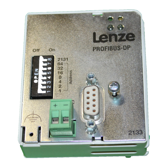
    Sobald ein Schalter S1 ... S7 = ON werden beim Einschalten die ƒ Konfigurationen aus allen Schalterstellungen aktiv. Die Lenze-Einstellung der Schalter (S1 - S8) ist OFF. Schalten Sie die Spannungsversorgung des Kommunikationsmoduls aus und anschließend wieder ein, um geänderte Einstellungen zu aktivieren.
  • Seite 29 Inbetriebnahme Adressierung Adresseinstellungen durch den frontseitigen DIP-Schalter Die Berechnung der Adresse (Dezimalzahl) ergibt sich durch Einsetzen des Schaltzustandes der Schalter S1 ... S7 (’0’ = OFF und ’1’ = ON) in die Gleichung: Adresse ⋅ 2 ⋅ 2 ⋅ 2 ⋅...
  • Seite 30 PROFIBUS-Stationsadresse Abbildung auf Codestelle C0009 (LECOM-Knotenadresse) nein (Master-Adressen) 3-99 ja (3-99) 100-125 ja (C0009=2) 126 (LENZE-Einstellung) ja (C0009=1) Tab. 1 Zuordnungen der Stationsadressen für die Antriebsregler  Hinweis! Im Zustand ”Power-On” kann vom Master-Klasse 2 mit dem ”Set_Slave_Adress”-Telegramm eine Teilnehmeradresse eingestellt werden.
  • Seite 31: Netzspannung Zuschalten

    Inbetriebnahme Netzspannung zuschalten Netzspannung zuschalten  Hinweis! Wenn Sie die externe Spannungsversorgung des Kommunikationsmoduls benutzen, schalten Sie diese ebenfalls ein. Auf der Frontseite des Kommunikationsmoduls müssen folgende LED’s leuchten: ƒ Die obere grüne LED: ”Statusanzeige Spannungsversorgung” ƒ Die untere grüne LED: ”Statusanzeige des Antriebs” Schutz vor unkontrolliertem Wiederanlauf ...
  • Seite 32: Statusanzeige

    Inbetriebnahme Statusanzeige Statusanzeige EMF2133IB PROFIBUS DP 2131 24V DC 2133 2133PFB003 Farbe Zustand Hinweise grün Kommunikationsmodul ist mit Spannung versorgt und hat Verbin-  dung zum Antriebsregler. Kommunikationsmodul ist nicht mit Spannung versorgt. Antriebsreg- ler oder externe Spannungsversorgung ist ausgeschaltet.
  • Seite 33: Technische Daten

    Technische Daten Allgemeine Daten und Einsatzbedingungen Technische Daten Allgemeine Daten und Einsatzbedingungen Kommunikationsrelevante Werte Daten Kommunikationsmedien RS 485 Netzwerk-Topologie ohne Repeater: Linie / mit Repeater: Linie oder Baum Anzahl Teilnehmer Standard: 32 (= 1 Bus-Segment) / mit Repeatern: 125 Leitungslänge / Segment 1200 m (abhängig von Übertragungsrate und verwendetem Kabeltyp) Kommunikations-Profil...
  • Seite 34 Technische Daten Allgemeine Daten und Einsatzbedingungen Protokoll-Daten Bereich Werte Prozessdaten-Wörter (PZD) 1 ... 12 Wörter (16 Bit / Wort) Parameterdaten-Kanal 4 Wörter PROFIBUS-DP-Nutzdatenlänge Prozessdaten-Wöerter (1 ... 12 Wörter) + Parameterdaten-Kanal (4 Wörter)  EDKMF2133 DE/EN/FR 4.0...
  • Seite 35: Technische Daten 6 Schutzisolierung

    Technische Daten Schutzisolierung Schutzisolierung Isolierung zwischen Bus und ... Art der Isolierung (nach EN 61800-5-1) Betriebsisolierung Bezugserde / PE Betriebsisolierung externer Versorgung Leistungsteil – 820X / 821X Basisisolierung – 822X / 8200 vector verstärkte Isolierung – 93XX / 9300 Servo PLC verstärkte Isolierung –...
  • Seite 36: Abmessungen

    Technische Daten Abmessungen Abmessungen PROFIBUS DP 2131 24V DC 2133 2133PFB003 61 mm 75 mm 28 mm 18 mm  EDKMF2133 DE/EN/FR 4.0...
  • Seite 37 Technische Daten Abmessungen  EDKMF2133 DE/EN/FR 4.0...
  • Seite 38 PE connection (only with 82XX) Note  below Fixing screw  Nameplate  39  Tip! Current documentations and software updates concerning Lenze products can be found on the Internet, respectively in the ”Services & Downloads” area under http://www.Lenze.com  EDKMF2133 DE/EN/FR 4.0...
  • Seite 39 Validity These Instructions are valid for ƒ EMF2133IB (PROFIBUS) communication modules as of version Vx. 0x. These Instructions are only valid together with the Operating Instructions for the standard devices permitted for the application. Identification 1D74 Type Id.-No. Prod.-No. Ser.-No.
  • Seite 40: Application Range

    Application range The communication module can be used together with basic devices as of the following nameplate data: Version Type Design Variant Explanation 33.820X E./C. Vxxx 8201 - 8204 33.821X E./C. Vxxx 8211 - 8218 33.822X Vxxx 8221 - 8227 33.824X E./C.
  • Seite 41 Contents Safety instructions ..........Definition of notes used .
  • Seite 42: Safety Instructions

    Safety instructions Definition of notes used Safety instructions Definition of notes used The following pictographs and signal words are used in this documentation to indicate dangers and important information: Safety instructions Structure of safety instructions:  Danger! (characterises the type and severity of danger) Note (describes the danger and gives information about how to prevent dangerous situations)
  • Seite 43: Residual Hazards

    Safety instructions Residual hazards Residual hazards  Danger! Observe the safety instructions and residual hazards included in the Instructions for the basic device.  EDKMF2133 DE/EN/FR 4.0...
  • Seite 44: Scope Of Supply

    Scope of supply Scope of supply  EMF2133IB PROFIBUS DP 2131 24V DC 2133 2133PFB003, E82ZAFX021/25 Scope of supply 2133 communication module Mounting Instructions Plug connector with screw connection, 2-pole  50  Tip! Additional information on this communication module that is supplementary to the information in these Mounting Instructions can be found at the Internet address shown on page 4.
  • Seite 45: Mechanical Installation

    Mechanical installation Mechanical installation 2102LEC014 ƒ Plug the communication module onto the basic device (here: 8200 vector). ƒ Screw the communication module to the basic device to ensure a good PE connection.  Note! For the internal supply of the communication module through the 8200 vector frequency inverter, the jumper in the interface opening must be adapted (see fig.
  • Seite 46: Electrical Installation

    Example: PROFIBUS with RS485 wiring (without repeater) Element Note Host e.g. PC or PLC with PROFIBUS master interface module Bus cable Adapt baud rate to bus cable length PROFIBUS slave Controller (see 40) which can be used with the EMF2133IB communication module  EDKMF2133 DE/EN/FR 4.0...
  • Seite 47: Wiring According To Emc

    Electrical installation Wiring according to EMC Wiring according to EMC Please observe the following for wiring according to EMC guidelines:  Note! With 820X and 821X controllers, communication can be impaired by ƒ electromagnetic interferences. For safe communication, use an additional cable between the PE connection of the basic device and the PE connection of the communication module.
  • Seite 48: Wiring

    Electrical installation Wiring Wiring ƒ Only use cables which correspond to the listed specifications, see (48). ƒ Provide connection to the controllers by means of the bus connector. The bus system will not be interrupted if the bus connector is removed from the controller. ƒ...
  • Seite 49 Electrical installation Wiring Number of devices connected to the bus 2133PFB004 Segment Master (M) Slave (S) Repeater (R)  Tip! Repeaters do not have a station address but in the calculation of the number of stations they reduce the number of stations by 1 on each side of the segment.
  • Seite 50: Voltage Supply

    Electrical installation Voltage supply Voltage supply External voltage supply  Note! With external voltage supply of the communication module, the active bus terminating resistor is fed independently of the operation of the basic device. Thus the bus system remains active even if the basic device is switched off or fails.
  • Seite 51 In the delivery status of the frequency inverters, these are not supplied ƒ internally. For internal voltage supply put the jumper on the position indicated below. ƒ Lenze setting Internal voltage supply (only external voltage supply)  EDKMF2133 DE/EN/FR 4.0...
  • Seite 52: Sub-D Socket Assignment

    Electrical installation Sub-D socket assignment Sub-D socket assignment View Designation Explanation RxD/TxD-P Data cable B (receive / send data plus) Request To Send (receive / send data, no differential signal) M5V2 Data reference potential (ground to 5V) P5V2 5 V DC / 30 mA (bus termination) RxD/TxD-N Data cable A (receive / send data minus) ...
  • Seite 53: Commissioning

    Commissioning Before switching on Commissioning Before switching on  Stop! Prior to switching on the mains voltage, check the wiring for completeness, short-circuit and earth fault.  Note! Manual settings are not required for the baud rate. The communication module is automatically adjusted to the baud rate of the master. ...
  • Seite 54: Initial Switch-On

    Provide software compatibility with the communication module 58 2133: Switch S8 = OFF 2131: Switch S8 = ON (with this setting, continue commissioning for the 2131 communication module) Lenze setting: S8 = OFF Drive-specific settings Documentation for the controller Prepare controller for communication 55...
  • Seite 55: Preparing The Controller For Communication

    82XX / 8200 vector frequency inverter Step Procedure The controller can only be enabled via PROFIBUS if the Lenze parameter 44 operating mode (C0001) is set to 3. This setting can be made using the EMZ9371BC keypad or directly via PROFIBUS.
  • Seite 56 93XX servo inverter Step Procedure For drive control via PROFIBUS set the Lenze parameter signal configuration (C0005) to a value xxx3. This change can be carried out using the EMZ9371BC keypad or the PROFIBUS. Select signal configuration 1013 (speed control) for the first commissioning.
  • Seite 57 ECS servo system, variants ”Speed & Torque” and ”Posi & Shaft” 1. For drive control via PROFIBUS use the EMZ9371BC keypad or the PROFIBUS and set the Lenze parameter signal configuration (C0005) to a value implementing communication via the AIF interface: ƒ...
  • Seite 58 Commissioning Preparing the controller for communication Software compatibility setting  Note! If the EMF2131IB communication module is replaced by the EMF2133IB communication module, do not change the host settings ƒ set switch S8 = ”ON” ƒ  EDKMF2133 DE/EN/FR 4.0...
  • Seite 59: Configuring The Host

    Commissioning Configuring the host Configuring the host The host must be configured before communication with the communication module is possible. Master settings For configuring the PROFIBUS, the device data base file of the communication module must be read into the master. ...
  • Seite 60: Activating The Bus Terminating Resistor

    Commissioning Activating the bus terminating resistor Activating the bus terminating resistor Place a bus terminating resistor only at the first and last physical bus station. The bus terminating resistor is integrated into the bus connector and can be activated via a switch.
  • Seite 61: Addressing

    If S1 ... S7 = ON, the configurations of all switch positions will become active ƒ when the device is switched on. The Lenze setting for the switches (S1 - S8) is OFF. Switch off the voltage supply of the communication module and switch it on again to activate the changed settings.
  • Seite 62 Commissioning Addressing Address settings through the front DIP switch The address (decimal number) is calculated by inserting the different switch states S1 ... S7 (’0’ = OFF and ’1’ = ON) into the equation: Address ⋅ 2 ⋅ 2 ⋅ 2 ⋅...
  • Seite 63 Mapping to code C0009 (LECOM node address) No (master addresses) 3-99 Yes (3-99) 100-125 Yes (C0009=2) 126 (LENZE setting) Yes (C0009=1) Tab. 2 Assignment of station addresses to controllers  Note! In the ”Power On” status, the class 2 master can set a device address via the ”Set_Slave_Address”...
  • Seite 64: Connecting The Mains Voltage

    Commissioning Connecting the mains voltage Connecting the mains voltage  Note! If you use the external voltage supply for the communication module, please switch it on. The following LEDs at the front of the communication module must be on: ƒ The top green LED: ”Status display for voltage supply” ƒ...
  • Seite 65: Status Display

    Commissioning Status display Status display EMF2133IB PROFIBUS DP 2131 24V DC 2133 2133PFB003 Colour Status Notes Green Communication module is supplied with voltage and connected to the  controller. Communication module is not supplied with voltage. Controller or external voltage supply is switched off.
  • Seite 66: Technical Data

    Technical data General data and operating conditions Technical data General data and operating conditions Communication-relevant data Values Communication media RS 485 Network topology without repeater: line / with repeater: line or tree Number of devices Standard: 32 (= 1 bus segment) / with repeaters: 125 Cable length / segment 1200 m (depending on the baud rate and the cable type used)
  • Seite 67 Technical data General data and operating conditions Protocol data Field Values Process data words (PCD) 1 ... 12 words (16 bits / word) Parameter data channel 4 words PROFIBUS-DP user data length Process data words (1 ... 12 words) + parameter data channel (4 words) ...
  • Seite 68: Protective Insulation

    Technical data Protective insulation Protective insulation Insulation between bus and ... Type of insulation (to EN 61800-5-1) Functional insulation Reference earth / PE Functional insulation External supply Power stage – 820X / 821X Basic insulation – 822X / 8200 vector Reinforced insulation –...
  • Seite 69: Dimensions

    Technical data Dimensions Dimensions PROFIBUS DP 2131 24V DC 2133 2133PFB003 61 mm 75 mm 28 mm 18 mm  EDKMF2133 DE/EN/FR 4.0...
  • Seite 70 Vis de fixation  Plaque signalétique  71  Conseil ! Les mises à jour de logiciels et les documentations récentes relatives aux produits Lenze sont disponibles dans la zone ”Téléchargements” du site Internet : http://www.Lenze.com  EDKMF2133 DE/EN/FR 4.0...
  • Seite 71 Validité Le présent document s’applique : ƒ aux modules de communication EMF2133IB (PROFIBUS) à partir de la version Vx. 0x. Ce document est uniquement valable avec la documentation relative aux appareils de base compatibles. Identification 1D74 Type Id.-No. Prod.-No. Ser.-No.
  • Seite 72 Utilisation Le module de communication peut être utilisé avec les appareils de base dont la plaque signalétique contient les indications suivantes : Version matérielle logicielle Type d’appareil Version Variante Précisions 33.820X E./C. Vxxx 8201 - 8204 33.821X E./C. Vxxx 8211 - 8218 33.822X Vxxx 8221 - 8227...
  • Seite 73 Sommaire Consignes de sécurité ..........Définition des conventions utilisées .
  • Seite 74: Consignes De Sécurité

    Consignes de sécurité Définition des conventions utilisées Consignes de sécurité Définition des conventions utilisées Pour indiquer des risques et des informations importantes, la présente documentation utilise les mots et symboles suivants : Consignes de sécurité Présentation des consignes de sécurité ...
  • Seite 75: Dangers Résiduels

    Consignes de sécurité Dangers résiduels Dangers résiduels  Danger ! Tenir compte des consignes de sécurité et des dangers résiduels décrits dans la documentation de l’appareil de base concerné.  EDKMF2133 DE/EN/FR 4.0...
  • Seite 76: Equipement Livré

    Equipement livré Equipement livré  EMF2133IB PROFIBUS DP 2131 24V DC 2133 2133PFB003, E82ZAFX021/25 Pos. Equipement livré Voir Module de communication 2133 Instructions de montage Bornier enfichable à vis, 2 bornes  82  Conseil ! Pour compléter ces instructions de montage, nous vous fournissons à l’adresse Internet indiquée à...
  • Seite 77: Installation Mécanique

    Installation mécanique Installation mécanique 2102LEC014 ƒ Enficher le module de communication sur l’appareil de base (ici : 8200 vector). ƒ Visser le module de communication sur l’appareil de base à l’aide de la vis de fixation pour assurer une bonne liaison avec la terre (PE). ...
  • Seite 78: Installation Électrique

    Exemple : PC ou API avec interface maître PROFIBUS Câble bus Adapter la vitesse de transmission à la longueur du câble bus. Esclave Appareil de base compatible (voir 72) avec le module de PROFIBUS communication EMF2133IB  EDKMF2133 DE/EN/FR 4.0...
  • Seite 79: Câblage Conforme Cem

    Installation électrique Câblage conforme CEM Câblage conforme CEM Pour s’assurer que le câblage est conforme aux exigences à respecter en matière de CEM, vérifier les points suivants :  Remarque importante ! Avec les variateurs de vitesse 820X et 821X, des perturbations ƒ...
  • Seite 80: Câblage

    Installation électrique Câblage Câblage ƒ Utiliser uniquement des câbles correspondant aux spécifications fournies, voir (80). ƒ Utiliser le connecteur de bus pour établir la liaison avec les variateurs de vitesse. Le fonctionnement du bus de terrain n’est pas interrompu lorsque le connecteur est retiré...
  • Seite 81 Installation électrique Câblage Nombre de participants 2133PFB004 Segment Maître (M) Esclave (S) Répétiteur (R)  Conseil ! Bien qu’ils ne soient pas dotés d’une adresse d’appareil, les répétiteurs entrent tout de même dans le calcul du nombre maxi de participants en réduisant, de chaque côté...
  • Seite 82: Alimentation

    Installation électrique Alimentation Alimentation Alimentation externe  Remarque importante ! En cas d’alimentation externe du module de communication, la résistance d’extrémité de bus active est alimentée indépendamment de l’état de l’appareil de base. Le bus de terrain reste actif même lorsque l’appareil de base est déconnecté.
  • Seite 83 Installation électrique Alimentation Alimentation CC interne  Remarque importante ! Les appareils de base avec une interface AIF étendue (face avant du 8200 vector) offrent la possibilité d’une alimentation interne. Sur l’illustration, la partie grise désigne la position du pont. A la livraison du variateur, une alimentation interne du module de ƒ...
  • Seite 84: Affectation De La Prise Sub-D

    Installation électrique Affectation de la prise Sub-D Affectation de la prise Sub-D Broche Désignation Description RxD/TxD-P Ligne de données B (réception/émission +) Request To Send (réception/émission, pas de signe de différenciation) M5V2 Potentiel de référence des données (masse par rapport à 5 V) P5V2 5 V CC / 30 mA (extrémité...
  • Seite 85: Mise En Service

    Mise en service Avant la première mise en service Mise en service Avant la première mise en service  Stop ! Avant la mise sous tension, contrôler l’ensemble du câblage et rechercher d’éventuels courts-circuits ou défauts de mise à la terre. ...
  • Seite 86: Première Mise En Service

    2133 : interrupteur DIP S8 = OFF 2131 : interrupteur DIP S8 = ON (passer directement à la mise en service du module de communication 2131) Réglage Lenze : S8 = OFF Réglages spécifiques à l’entraînement Documentation du variateur de vitesse Préparation de l’appareil de base pour la communication...
  • Seite 87 Mise en service Première mise en service Etape Opération Voir Adressage des participants au bus 94 Chaque participant doit disposer d’une adresse distincte. Vous pouvez désormais communiquer avec le variateur, c’est-à-dire échanger des données process (consignes et valeurs réelles), lire tous les codes, modifier tous les codes programmables.
  • Seite 88: Préparation De L'appareil De Base Pour La Communication

    Voir Pour pouvoir débloquer le variateur de vitesse via PROFIBUS, régler le 76 paramètre Lenze ”Mode de commande” (C0001) sur 3. Ceci peut être effectué à l’aide du clavier de commande EMZ9371BC ou directement via PROFIBUS. Exemples pour PROFIBUS Write (C0001=3) : 76...
  • Seite 89 Voir Afin de pouvoir commander le variateur de vitesse via PROFIBUS, régler le paramètre Lenze ”Configuration des signaux” (C0005) sur xxx3. Ceci peut être effectué à l’aide du clavier de commande EMZ9371BC ou directement via PROFIBUS. Lors de la première mise en service, nous recommandons la configuration de signaux 1013 (régulation de vitesse).
  • Seite 90 Systèmes Servo ECS : variantes ”Speed & Torque” et ”Posi & Shaft” 1. Afin de pouvoir commander le variateur de vitesse via PROFIBUS, régler le paramètre Lenze ”Configuration des signaux” (C0005) sur une valeur permettant de réaliser la communication via interface AIF. Ceci peut être effectué à l’aide du clavier de commande EMZ9371BC ou directement via PROFIBUS.
  • Seite 91 Réglage de la compatibilité logicielle  Remarque importante ! Lorsque le module de communication EMF2131IB est remplacé par le module de communication EMF2133IB : ne pas modifier les réglages sur le maître, ƒ positionner l’interrupteur DIP S8 sur ”ON”. ƒ...
  • Seite 92: Configuration Du Système Maître

    Mise en service Configuration du système maître Configuration du système maître Pour pouvoir communiquer via le module de communication, il faut d’abord configurer le maître. Réglages effectués sur le maître Pour configurer le PROFIBUS, le fichier descriptif du module de communication doit être chargé...
  • Seite 93: Activation De La Résistance D'extrémité De Bus

    Mise en service Activation de la résistance d’extrémité de bus Activation de la résistance d’extrémité de bus La résistance d’extrémité de bus doit être activée uniquement sur le premier et le dernier participant au bus. La résistance d’extrémité de bus est intégrée dans la prise de raccordement au bus et activée à...
  • Seite 94: Adressage

    Dès qu’un interrupteur DIP S1 ... S7 est en position ON, toutes les ƒ configurations correspondantes sont activées. Le réglage Lenze des interrupteurs DIP (S1 - S8) est OFF. Pour activer les modifications apportées aux réglages, couper brièvement l’alimentation du module de communication et du variateur de vitesse.
  • Seite 95 Mise en service Adressage Réglage de l’adresse via les interrupteurs DIP situés sur la face avant Dans l’équation ci-dessous, l’adresse calculée (chiffre décimal) résulte de la position des interrupteurs DIP S1 à S7 (’0’ = OFF et ’1’ = ON). Adresse ⋅...
  • Seite 96 Apparaît dans le code C0009 (adresse du noeud LECOM) Non (adresses maître) 3-99 Oui (3-99) 100-125 Oui (C0009=2) 126 (réglage LENZE) Oui (C0009=1) Tab. 3 Affectation des adresses de station aux variateurs de vitesse  Remarque importante ! A l’état ”Power On”, il est possible de régler l’adresse d’un participant à l’aide du maître classe 2 via le télégramme ”Set_Slave_Adress”.
  • Seite 97: Mise Sous Tension

    Mise en service Mise sous tension Mise sous tension  Remarque importante ! Enclencher également la tension d’alimentation externe du module de communication, si utilisée. Les LED suivantes, situées sur la face avant du module de communication, doivent être allumées : ƒ...
  • Seite 98: Affichage D'état

    Mise en service Affichage d’état Affichage d’état EMF2133IB PROFIBUS DP 2131 24V DC 2133 2133PFB003 Pos. Couleur Etat LED Explication Le module de communication est sous tension et la liaison avec le  verte variateur de vitesse est établie. Le module de communication n’est pas sous tension. Le variateur est déconnecté...
  • Seite 99: Spécifications Techniques

    Spécifications techniques Caractéristiques générales et conditions d’utilisation Spécifications techniques Caractéristiques générales et conditions d’utilisation Données relatives à la Valeurs communication Support de communication RS485 Topologie du réseau Sans répétiteur : ligne ; avec répétiteurs : ligne ou arborescence Nombre de participants Standard : 32 (= 1 segment de bus) ;...
  • Seite 100 Spécifications techniques Caractéristiques générales et conditions d’utilisation Caractéristiques du protocole Domaine Valeurs Mots de données process (PZD) 1 ... 12 mots (16 bits/mot) Canal de données paramètres 4 mots Longueur des données utiles Mots de données process (1 ..12 mots) + canal de données PROFIBUS-DP paramètres (4 mots) ...
  • Seite 101: Isolement

    Spécifications techniques Isolement Isolement Isolement entre bus et ... Type d’isolement (selon EN 61800-5-1) Isolement fonctionnel point de terre/PE Isolement fonctionnel alimentation externe partie puissance – 820X/821X Isolement principal – 822X/8200 vector Isolement renforcé – 93XX/9300 Servo PLC Isolement renforcé –...
  • Seite 102: Encombrements

    Spécifications techniques Encombrements Encombrements PROFIBUS DP 2131 24V DC 2133 2133PFB003 61 mm 75 mm 28 mm 18 mm  EDKMF2133 DE/EN/FR 4.0...
  • Seite 103 Spécifications techniques Encombrements  EDKMF2133 DE/EN/FR 4.0...
  • Seite 104  Lenze Drive Systems GmbH EDKMF2133 Hans-Lenze-Straße 1 DE/EN/FR 4.0 D-31855 Aerzen © 02/2006 Germany TD06 +49 (0) 51 54 82-0 Service 00 80 00 24 4 68 77 (24 h helpline) Service +49 (0) 51 54 82-1112 E-Mail Lenze@Lenze.de Internet www.Lenze.com...

Inhaltsverzeichnis