Herunterladen Inhalt Inhalt Diese Seite drucken
Lenze E82ZAFSC Montageanleitung

Lenze E82ZAFSC Montageanleitung

Funktionsmodul
Vorschau ausblenden Andere Handbücher für E82ZAFSC:

Werbung

Verfügbare Sprachen

Verfügbare Sprachen

EDK82ZAFSC
.5r÷
STANDARD−I/O
E82ZAFSC
Funktionsmodul
Function module
Module de fonction
Montageanleitung
Mounting Instructions
Instructions de montage
l

Werbung

Inhaltsverzeichnis
loading

Inhaltszusammenfassung für Lenze E82ZAFSC

  • Seite 1 EDK82ZAFSC .5r÷ Montageanleitung Mounting Instructions Instructions de montage STANDARD−I/O E82ZAFSC Funktionsmodul Function module Module de fonction...
  • Seite 2 Lesen Sie zuerst diese Anleitung und die Dokumentation zum Grundgerät, bevor Sie mit den Arbeiten beginnen! Beachten Sie die enthaltenen Sicherheitshinweise. Please read these instructions and the documentation of the standard device before you start working! Observe the safety instructions given therein! Lire le présent fascicule et la documentation relative à...
  • Seite 3 E82ZAFS002A...
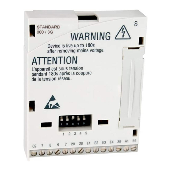
  • Seite 4 Schalter zur Konfigurierung des analogen Frequenzsollwertes an Klemme X3/8 ^ 14 Digitale und analoge Ein− und Ausgänge, Klemmenleiste X3 Typenschild 0Abb. 0Tab. 0 Tipp! Aktuelle Dokumentationen und Software−Updates zu Lenze Produkten finden Sie im Internet jeweils im Bereich "Services & Downloads" unter http://www.Lenze.com EDK82ZAFSC DE/EN/FR 4.0...
  • Seite 5: Funktion

    Gerätegeneration Variante 000: Standardausführung 001: Verlackte Ausführung Hardwarestand Bestellbezeichnung E82ZAFSC00x Funktion Das Funktionsmodul ermöglicht das Ansteuern von Lenze Frequenzumrichtern und der Lenze Antriebs−SPS mit analogen und digitalen Steuersignalen. Einsetzbarkeit Einsetzbare Grundgeräte Einsetzbar ab Grundgeräte−Version Frequenzumrichter 8200 vector Vx14 8200 motec Vx14 Antriebs−SPS...
  • Seite 6: Inhaltsverzeichnis

    ............Mit Lenze−Einstellung .
  • Seite 7: Sicherheitshinweise

    Sicherheitshinweise Definition der verwendeten Hinweise Sicherheitshinweise Definition der verwendeten Hinweise Um auf Gefahren und wichtige Informationen hinzuweisen, werden in dieser Dokumenta- tion folgende Piktogramme und Signalwörter verwendet: Sicherheitshinweise Aufbau der Sicherheitshinweise: Gefahr! (kennzeichnet die Art und die Schwere der Gefahr) Hinweistext (beschreibt die Gefahr und gibt Hinweise, wie sie vermieden werden kann) Piktogramm und Signalwort...
  • Seite 8: Restgefahren

    Sicherheitshinweise Restgefahren Restgefahren Gefahr! Beachten Sie die in den Anleitungen zum Grundgerät enthaltenen Sicherheitshinweise und Restgefahren. EDK82ZAFSC DE/EN/FR 4.0...
  • Seite 9: Lieferumfang

    Lieferumfang Lieferumfang E82ZAFX019/misc, E82ZAFS002A Pos. Lieferumfang Funktionsmodul E82ZAFSC Schraubendreher Aufkleber Montageanleitung EDK82ZAFSC DE/EN/FR 4.0...
  • Seite 10: Mechanische Installation

    Mechanische Installation Mechanische Installation Folgen Sie zur mechanischen Installation des Funktionsmoduls den Hinweisen in der Mon- tageanleitung des Grundgerätes. Die Montageanleitung des Grundgerätes ƒ ist Teil des Lieferumfangs und liegt jedem Gerät bei. ƒ gibt Hinweise, um Beschädigungen durch unsachgemäße Behandlung zu vermeiden. ƒ...
  • Seite 11: Elektrische Installation

    Elektrische Installation EMV−gerechte Verdrahtung Elektrische Installation EMV−gerechte Verdrahtung Für eine EMV−gerechte Verdrahtung beachten Sie folgende Punkte: Hinweis! Steuerleitungen getrennt von Motorleitungen verlegen. ƒ Schirme so weit wie möglich an die Klemmen führen (ungeschirmte ƒ Aderlänge < 40 mm). Legen Sie die Schirme der Steuerleitungen bzw. Datenleitungen wie folgt ƒ...
  • Seite 12: Verdrahtung

    Elektrische Installation Verdrahtung Verdrahtung Daten der Anschlussklemmen Elektrischer Anschluss Klemmleiste mit Schraubanschluss Anschlussmöglichkeiten starr: 1,5 mm (AWG 16) flexibel: ohne Aderendhülse 1,0 mm (AWG 18) mit Aderendhülse, ohne Kunststoffhülse 0,5 mm (AWG 20) mit Aderendhülse, mit Kunststoffhülse 0,5 mm (AWG 20) Anzugsmoment 0,22 ...
  • Seite 13 Elektrische Installation Verdrahtung Versorgung über die interne Spannungsquelle (X3/20): X3/28, Reglersperre (CINH) X3/E1 ..X3/E4, digitale Eingänge GND2 GND1 GND1 +20V 20 28 E1 E2 E3 E4 39 A1 59 AOUT1 AIN1 DIGOUT1 1k … 10k E82ZAFS004 Versorgung über eine externe Spannungsquelle: X3/28, Reglersperre (CINH) X3/E1 ...
  • Seite 14 Ausgangspegel 0 … +10 V: Offset (C0109/C0422) und Verstärkung (C0108/C0420) anpassen Offset (C0026) und Verstärkung (C0027) für jedes Funktionsmodul separat abgleichen: Nach Austausch des Funktionsmoduls oder des Grundgerätes Nach Laden der Lenze−Einstellung Wahlweise Frequenzeingang 0 … 10 kHz einspurig oder 0 ... 1 kHz zweispurig, Konfiguration über C0425...
  • Seite 15: Inbetriebnahme

    Inbetriebnahme Vor dem ersten Einschalten Inbetriebnahme Vor dem ersten Einschalten Hinweis! Wenn Sie die Inbetriebnahme mit einer von der Lenze−Einstellung ƒ abweichenden Konfiguration durchführen, lesen Sie die Anweisungen "Individuelle Einstellungen" ^ 17. Achten Sie darauf, ƒ – dass Sie mit dem DIP−Schalter am Funktionsmodul den Sollwertbereich richtig eingestellt haben, siehe ^ 16.
  • Seite 16: Schalterstellung

    DIP−Schalter auf Spannungsbereich 0 ... 5 V einstellen. Andernfalls kann nicht der ganze Drehzahlbereich durchfahren werden. Signal an X3/8 C0034 Schalterstellung 0 ... 5 V 0 ... 10 V (Lenze−Einstellung) 0 ... 20 mA 4 ... 20 mA 4 ... 20 mA drahtbruchüberwacht −10 V ... +10 V...
  • Seite 17: Mit Lenze−Einstellung

    Inbetriebnahme Mit Lenze−Einstellung Mit Lenze−Einstellung Schritt Vorgehensweise Bemerkungen Netzspannung zuschalten. Das Grundgerät ist nach ca. 1 Sekunde betriebsbereit. Die Reglersperre ist aktiv. Reaktion des Grundgerätes Die grüne LED blinkt. Keypad: (falls aufgesteckt) Digitale Eingänge ansteu- Lenze−Einstellung ern. Rechtslauf: – E1, E2, E3, E4: LOW Linkslauf: –...
  • Seite 18 Inbetriebnahme Mit Lenze−Einstellung Hinweis! Das Grundgerät ist nur funktionsfähig, wenn HIGH−Pegel an X3/28 anliegt ƒ (Reglerfreigabe über Klemme). – Beachten Sie, dass die Reglersperre über mehrere Quellen gesetzt werden kann. Die Quellen wirken wie eine Reihenschaltung von Schaltern. – Wenn der Antrieb trotz Reglerfreigabe über X3/28 nicht anläuft, überprüfen Sie, ob noch über eine andere Quelle Reglersperre gesetzt...
  • Seite 19: Technische Daten

    Technische Daten Anschlussdaten Technische Daten Anschlussdaten Auflösung: 10 Bit Linearitätsfehler: ±0,5 % Temperaturfehler: 0,3 % (0 … +60 °C) Belastbarkeit I = 2 mA Auflösung: 10 Bit Linearitätsfehler: ±0,5 % Temperaturfehler: 0,3 % (0 … +60 °C) Eingangswiderstand > 50 k (bei Spannungssignal) Eingang = 250...
  • Seite 20: Einsatzbedingungen

    Technische Daten Einsatzbedingungen Einsatzbedingungen Umgebungsbedingungen Klimatische Bedingungen Lagerung 1 K3 nach IEC/EN 60721−3−1 − 25 ... + 60 °C Transport 2 K3 nach IEC/EN 60721−3−2 − 25 ... + 70 °C Betrieb 3 K3 nach IEC/EN 60721−3−3 − 20 ... + 60 °C Verschmutzungsgrad 2 nach IEC/EN 61800−5−1 Schutzart...
  • Seite 21: Abmessungen

    Technische Daten Abmessungen Abmessungen E82ZAFS002A alle Maße in mm EDK82ZAFSC DE/EN/FR 4.0...
  • Seite 22 Digital and analog inputs and outputs, terminal strip X3 ^ 23 Nameplate 0Fig. 0Tab. 0 Tip! Current documentation and software updates concerning Lenze products can be found on the Internet in the "Services & Downloads" area under http://www.Lenze.com EDK82ZAFSC DE/EN/FR 4.0...
  • Seite 23 Hardware version Order designation E82ZAFSC00x Function The function module enables the user to control Lenze frequency inverters and Drive PLCs with analog and digital control signals. Application range Can be used together with: Can be used as of standard device version...
  • Seite 24 ............Commissioning using Lenze settings .
  • Seite 25: Safety Instructions

    Safety instructions Definition of notes used Safety instructions Definition of notes used The following pictographs and signal words are used in this documentation to indicate dangers and important information: Safety instructions Structure of safety instructions: Danger! (characterises the type and severity of danger) Note (describes the danger and gives information about how to prevent dangerous situations)
  • Seite 26: Residual Hazards

    Safety instructions Residual hazards Residual hazards Danger! Observe the safety instructions and residual hazards included in the instructions for the standard device. EDK82ZAFSC DE/EN/FR 4.0...
  • Seite 27: Scope Of Supply

    Scope of supply Scope of supply E82ZAFX019/misc, E82ZAFS002A Pos. Scope of supply E82ZAFSC function module Screw driver Sticker Mounting Instructions EDK82ZAFSC DE/EN/FR 4.0...
  • Seite 28: Mechanical Installation

    Mechanical installation Mechanical installation Follow the notes given in the Mounting Instructions for the standard device for the mechanical installation of the function module. The Mounting Instructions for the standard device ƒ are part of the scope of supply and are enclosed with each device. ƒ...
  • Seite 29: Electrical Installation

    Electrical installation Wiring according to EMC Electrical installation Wiring according to EMC Please observe the following for wiring according to EMC guidelines: Note! Separate control cables from motor cables. ƒ Lead the shields as far as possible to the terminals (unshielded core length ƒ...
  • Seite 30: Wiring

    Electrical installation Wiring Wiring Terminal data Electrical connection Terminal strip with screw connection Possible connections rigid: 1.5 mm (AWG 16) flexible: without wire end ferrule 1.0 mm (AWG 18) with wire end ferrule, without plastic sleeve 0.5 mm (AWG 20) with wire end ferrule, with plastic sleeve 0.5 mm (AWG 20)
  • Seite 31 Electrical installation Wiring Supply via the internal voltage source (X3/20): X3/28, controller inhibit (CINH) X3/E1 ..X3/E4, digital inputs GND2 GND1 GND1 +20V 20 28 E1 E2 E3 E4 39 A1 59 AOUT1 AIN1 DIGOUT1 1k … 10k E82ZAFS004 Supply via an external voltage source: X3/28, controller inhibit (CINH) X3/E1 ...
  • Seite 32 Adjust offset (C0026) and gain (C0027) separately for each function module: After replacing the function module or the standard device After loading the Lenze setting Alternatively frequency input 0 … 10 kHz single−tracked or 0 ... 1 kHz double−tracked, configuration via C0425 EDK82ZAFSC DE/EN/FR 4.0...
  • Seite 33: Commissioning

    Commissioning Before switching on Commissioning Before switching on Note! If your configuration differs from the Lenze settings, please read the ƒ ^ 35 instructions given under "Individual settings" Please check ƒ – that the setpoint range is set correctly for the function module using...
  • Seite 34: Switch Position

    0 ... 5 V. Otherwise it is not possible to use the whole speed range. Signal at X3/8 C0034 Switch position 0 ... 5 V 0 ... 10 V (Lenze setting) 0 ... 20 mA 4 ... 20 mA 4 ... 20 mA Open−circuit monitoring −10 V ...
  • Seite 35: Commissioning Using Lenze Settings

    Commissioning Commissioning using Lenze settings Commissioning using Lenze settings Step Procedure Remarks Switch on the mains The controller is ready for operation after approx. 1 second. voltage. Controller inhibit is active. Drive response: The green LED is blinking. Keypad: (if attached) Control digital inputs.
  • Seite 36 Commissioning Commissioning using Lenze settings Note! The controller is only ready for operation if a HIGH signal is applied to ƒ X3/28 (controller enable via terminal). – Please observe that the controller can be inhibited through various sources. All sources act like a series connection of switches.
  • Seite 37: Technical Data

    Technical data Connection data Technical data Connection data Resolution: 10 bit Linearity error: ±0.5 % Temperature error: 0.3 % (0 … +60 °C) Carrying capacity I = 2 mA Resolution: 10 bit Linearity error: ±0.5 % Temperature error: 0.3 % (0 … +60 °C) Input resistance >...
  • Seite 38: Operating Conditions

    Technical data Operating conditions Operating conditions Ambient conditions Climatic conditions Storage 1 K3 acc. to IEC/EN 60721−3−1 − 25 ... + 60 °C Transport 2 K3 acc. to IEC/EN 60721−3−2 − 25 ... + 70 °C Operation 3 K3 acc. to IEC/EN 60721−3−3 −...
  • Seite 39: Dimensions

    Technical data Dimensions Dimensions E82ZAFS002A All dimensions in mm EDK82ZAFSC DE/EN/FR 4.0...
  • Seite 40 Entrées et sorties numériques et analogiques, bornier X3 ^ 41 Plaque signalétique 0Fig. 0Tab. 0 Conseil ! Les mises à jour de logiciels et les documentations récentes relatives aux produits Lenze sont disponibles dans la zone "Téléchargements" du site Internet : http://www.Lenze.com EDK82ZAFSC DE/EN/FR 4.0...
  • Seite 41 Validité Le présent document s’applique aux modules suivants : ƒ Modules de fonction E82ZAFSC (E/S standard) à partir de la version 3A : Ce document est uniquement valable avec la documentation relative aux appareils de base compatibles. Identification ‚ƒ ...
  • Seite 42 ..........Avec réglage Lenze .
  • Seite 43: Consignes De Sécurité

    Consignes de sécurité Définition des conventions utilisées Consignes de sécurité Définition des conventions utilisées Pour indiquer des risques et des informations importantes, la présente documentation utilise les mots et symboles suivants : Consignes de sécurité Présentation des consignes de sécurité Danger ! (Le pictogramme indique le type de risque.) Explication...
  • Seite 44: Dangers Résiduels

    Consignes de sécurité Dangers résiduels Dangers résiduels Danger ! Tenir compte des consignes de sécurité et des dangers résiduels décrits dans la documentation de l’appareil de base concerné. EDK82ZAFSC DE/EN/FR 4.0...
  • Seite 45: Equipement Livré

    Equipement livré Equipement livré E82ZAFX019/misc, E82ZAFS002A Pos. Equipement livré Module de fonction E82ZAFSC Tournevis Autocollant Instructions de montage EDK82ZAFSC DE/EN/FR 4.0...
  • Seite 46: Installation Mécanique

    Installation mécanique Installation mécanique Pour l’installation mécanique du module de fonction, suivre les consignes fournies dans les instructions de montage de l’appareil de base. Les instructions de montage de l’appareil de base ƒ font partie de la livraison standard et sont comprises dans l’emballage, ƒ...
  • Seite 47: Installation Électrique

    Installation électrique Câblage conforme CEM Installation électrique Câblage conforme CEM Pour réaliser un câblage conforme CEM, respectez les points suivants : Remarque importante ! Poser les câbles de commande séparément des câbles moteur. ƒ Conduire le blindage aussi loin que possible vers les bornes (longueur de fil ƒ...
  • Seite 48: Câblage

    Installation électrique Câblage Câblage Spécifications des bornes de raccordement Raccordement électrique Bornier à vis Raccordements possibles Rigide : 1,5 mm (AWG 16) Souple : sans embout 1,0 mm (AWG 18) avec embout, sans cosse en plastique 0,5 mm (AWG 20) avec embout et cosse en plastique 0,5 mm (AWG 20)
  • Seite 49 Installation électrique Câblage Alimentation via tension interne (X3/20) : X3/28, blocage variateur (CINH) X3/E1 ..X3/E4, entrées numériques GND2 GND1 GND1 +20V 20 28 E1 E2 E3 E4 39 A1 59 AOUT1 AIN1 DIGOUT1 1k … 10k E82ZAFS004 Alimentation via tension externe : X3/28, blocage variateur (CINH) X3/E1 ...
  • Seite 50 Installation électrique Câblage Type de signal Fonction Niveau (réglage Lenze : en caractères gras) Sortie Fréquence de sortie 0 … +6 V analogique 0 … +10 V − GND1, potentiel de référence pour les signaux − analogiques Entrée Entrée pour valeur réelle ou consigne analogique Commuter la plage à...
  • Seite 51: Mise En Service

    Avant la première mise sous tension Mise en service Avant la première mise sous tension Remarque importante ! Pour la mise en service d’une configuration qui diffère du réglage Lenze, ƒ ^ 53 lire les instructions fournies au paragraphe "Réglages individuels"...
  • Seite 52: Position De L'interrupteur

    0 ... 5 V. Autrement, il ne sera pas possible de parcourir la plage de vitesse dans son intégralité. Signal au niveau de X3/8 C0034 Position de l’interrupteur 0 ... 5 V 0 ... 10 V (réglage Lenze) 0 ... 20 mA 4 ... 20 mA 4 ... 20 mA avec protection contre rupture de fil −10 V ...
  • Seite 53: Avec Réglage Lenze

    Mise en service Avec réglage Lenze Avec réglage Lenze Etape Action Remarques Activer la tension réseau L’appareil de base est opérationnel après env. 1 seconde. Le blocage variateur est activé. Réaction de l’appareil de base La LED verte clignote. Clavier de commande : (s’il est raccordé)
  • Seite 54 Mise en service Avec réglage Lenze Remarque importante ! L’appareil de base n’est opérationnel que lorsque le niveau HAUT est requis ƒ au niveau de la borne X3/28 (déblocage du variateur par la borne). – Veiller à ce que le blocage variateur puisse être défini au moyen de plusieurs sources.
  • Seite 55: Spécifications Techniques

    Spécifications techniques Données de raccordement Spécifications techniques Données de raccordement Résolution : 10 bits Erreur de linéarité : ±0,5 % Erreur de température : 0,3 % (0 … +60 °C) Capacité de charge I = 2 mA Résolution : 10 bits Erreur de linéarité...
  • Seite 56: Conditions D'utilisation

    Spécifications techniques Conditions d’utilisation Conditions d’utilisation Conditions ambiantes Conditions climatiques Stockage 1 K3 selon CEI/EN 60721−3−1 − 25 ... + 60 °C Transport 2 K3 selon CEI/EN 60721−3−2 − 25 ... + 70 °C Fonctionnement 3 K3 selon CEI/EN 60721−3−3 −...
  • Seite 57: Encombrements

    Spécifications techniques Encombrements Encombrements E82ZAFS002A Toutes les cotes en mm EDK82ZAFSC DE/EN/FR 4.0...
  • Seite 58 Lenze Drive Systems GmbH EDK82ZAFSC Hans−Lenze−Straße 1 DE/EN/FR 4.0 D−31855 Aerzen © 06/2007 Germany TD06 +49 (0) 51 54 82−0 Service 00 80 00 24 4 68 77 (24 h helpline) Ê Service +49 (0) 51 54 82−1112 E−Mail Lenze@Lenze.de Internet www.Lenze.com...

Inhaltsverzeichnis