Lenze E94AYCPM Montageanleitung
Vorschau ausblenden
Andere Handbücher für E94AYCPM:
- Montageanleitung (114 Seiten) ,
- Kommunikationshandbuch (125 Seiten)

Verwandte Anleitungen für Lenze E94AYCPM


Inhaltszusammenfassung für Lenze E94AYCPM
- Seite 2 Lesen Sie zuerst diese Anleitung, bevor Sie mit den Arbeiten beginnen! Beachten Sie die enthaltenen Sicherheitshinweise. Please read these Instructions before you start working! Follow the enclosed safety instructions. Veuillez lire attentivement cette documentation avant toute action ! Les consignes de sécurité doivent impérativement être respectées.
- Seite 3 E894YCPM001A...
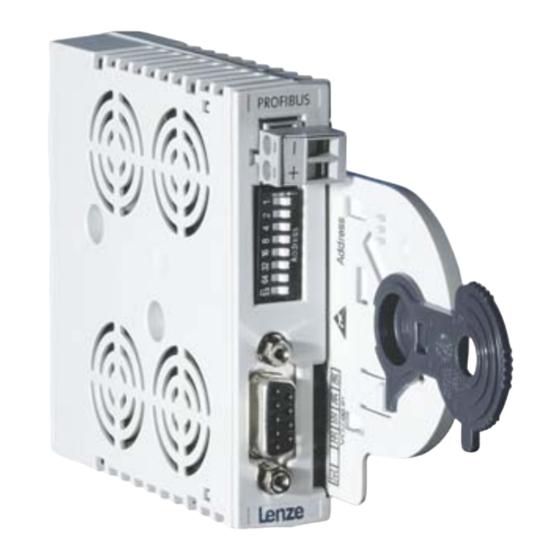
- Seite 4 Pos. Lieferumfang Kommunikationsmodul E94AYCPM Montageanleitung Pos. Steckverbindungen / Schalter Steckbare Klemmenleiste mit Schraubanschluss, 2-polig, zur externen Versorgung des Kommunikationsmoduls DIP-Schalter zur Adressierung des Teilnehmers Anschluss für PROFIBUS-DP Ausführung: Sub-D-Buchse, 9-polig Zustandsmeldungen LED-Zustand Erläuterung Pos. MS (grün)
-
Seite 5: Montage
Montage E94AYCXX001G Demontage E94AYCXX001H EDK94AYCPM DE/EN/FR 1.0... - Seite 6 Gültigkeit Diese Anleitung ist gültig für ƒ Kommunikationsmodule E94AYCPM (PROFIBUS-DP) ab Version VA.05. Identifikation E94YCEI003C E94YCXX006 Typenschlüssel Produktreihe Gerätegeneration Modulkennung: Erweiterungsmodul Modultyp: Kommunikationsmodul PROFIBUS-DP Hardwarestand Softwarestand Einsetzbarkeit Die Verwendung dieses Kommunikationsmoduls ist zulässig mit Grundgeräten der Produktreihe 9400 ab der Typenschildbezeichnung ƒ...
-
Seite 7: Sicherheitshinweise
Sicherheitshinweise Sicherheit Gefahr! Unsachgemäßer Umgang mit dem Kommunikationsmodul und dem Grundgerät kann schwere Personenschäden und Sachschäden verursachen. Beachten Sie die in den Anleitungen zum Grundgerät enthaltenen Sicherheitshinweise und Restgefahren. EDK94AYCPM DE/EN/FR 1.0... -
Seite 8: Elektrische Installation
Elektrische Installation Elektrische Installation Externe Spannungsversorgung Versorgen Sie bei Bedarf das Kommunikationsmodul über die zweipolige Steckerleiste mit einer separaten Versorgungsspannung. Verwenden Sie bei größeren Entfernungen zwischen den Schaltschränken in jedem Schalt- schrank ein separates Netzteil. Anschluss Steckerleiste, Pos. : Steckerleiste Bezeichnung Erläuterung Vcc24... - Seite 9 Elektrische Installation Belegung der Sub-D-Buchse Anschluss des PROFIBUS an 9-poliger Sub-D-Buchse, Pos. : Ansicht Bezeichnung Erläuterung frei frei RxD/TxD-P Datenleitung-B (Empfangsdaten- / Sendedaten-Plus) Request To Send (Empfangsdaten / Sendedaten, kein Diffe- renzsignal) M5V2 Datenbezugspotential (Masse zu 5V) P5V2 5 V DC / 30 mA (Busabschluss) frei RxD/TxD-N Datenleitung-A (Empfangsdaten- / Sendedaten-Minus)
- Seite 10 Elektrische Installation Spezifikation des Übertragungskabels Bitte folgen Sie bei der Verwendung des Signalkabels unseren Empfehlungen. Spezifikation Buskabel Leitungswiderstand 135 - 165 Ω/km, (f = 3 - 20 MHz) Kapazitätsbelag ≤ 30 nF/km Schleifenwiderstand < 110 Ω/km Aderdurchmesser > 0,64 mm Aderquerschnitt >...
- Seite 11 Elektrische Installation EDK94AYCPM DE/EN/FR 1.0...