Herunterladen Inhalt Inhalt Diese Seite drucken
Lenze E94AYCPM Montageanleitung
Vorschau ausblenden Andere Handbücher für E94AYCPM:
Inhaltsverzeichnis

Werbung

Verfügbare Sprachen
  • DE

Verfügbare Sprachen

  • DEUTSCH, seite 4
EDK94AYCPM
.Bö$
L−force Communication
PROFIBUS
E94AYCPM
Kommunikationsmodul
Communication module
Module de communication
Módulo de comunicaciones
Modulo di comunicazione
Montageanleitung
Mounting Instructions
Instructions de montage
Instrucciones para el montaje
Istruzioni per il montaggio
l

Werbung

Inhaltsverzeichnis
loading

Inhaltszusammenfassung für Lenze E94AYCPM

  • Seite 1 EDK94AYCPM L−force Communication .Bö$ Montageanleitung Mounting Instructions Instructions de montage Instrucciones para el montaje Istruzioni per il montaggio PROFIBUS E94AYCPM Kommunikationsmodul Communication module Module de communication Módulo de comunicaciones Modulo di comunicazione...
  • Seite 3 Lesen Sie zuerst diese Anleitung, bevor Sie mit den Arbeiten beginnen! Beachten Sie die enthaltenen Sicherheitshinweise. Please read these instructions before you start working! Follow the enclosed safety instructions. Veuillez lire attentivement cette documentation avant toute action ! Les consignes de sécurité doivent impérativement être respectées. Lea las instrucciones antes de empezar a trabajar.
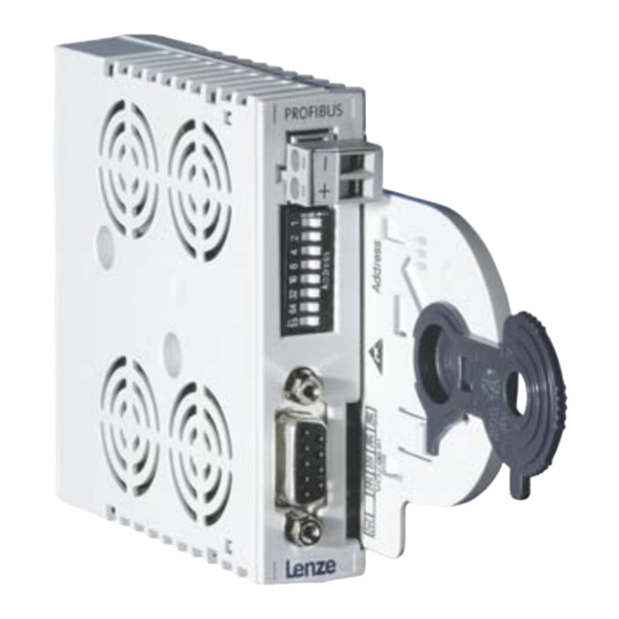
  • Seite 4 E94YCPM001A 0Abb. 0Tab. 0 Pos. Beschreibung Ausführliche Information ^ 22 S200 DIP−Schalter zur Einstellung der Stationsadresse Kompatibilität zum Kommunikationsmodul EMF2133IB ^ 21 X200 Anschluss für externe Spannungsversorgung 2−polige Steckerleiste mit Schraubanschluss ^ 18 X201 PROFIBUS−Anschluss 9−polige Sub−D−Buchse EDK94AYCPM DE/EN/FR/ES/IT 6.1...
  • Seite 5 Pos. Beschreibung Ausführliche Information ^ 25 LED−Statusanzeigen zur Diagnose EDK94AYCPM DE/EN/FR/ES/IT 6.1...
  • Seite 6: Inhaltsverzeichnis

    Inhalt Über diese Dokumentation ......... . Verwendete Konventionen .
  • Seite 7: Über Diese Dokumentation

    Softwarestand PROFIBUS E94AYCPM 01.00 Zielgruppe Diese Dokumentation wendet sich an Personen, die das beschriebene Produkt nach Projekt- vorgabe installieren und in Betrieb nehmen. Tipp! Informationen und Hilfsmittel rund um die Lenze−Produkte finden Sie im Download−Bereich unter www.lenze.com EDK94AYCPM DE/EN/FR/ES/IT 6.1...
  • Seite 8: Verwendete Konventionen

    Über diese Dokumentation Verwendete Konventionen Verwendete Konventionen Diese Dokumentation verwendet folgende Konventionen zur Unterscheidung verschiede- ner Arten von Information: Informationsart Auszeichnung Beispiele/Hinweise Zahlenschreibweise Dezimaltrennzeichen Punkt Es wird generell der Dezimalpunkt verwendet. Beispiel: 1234.56 Symbole Seitenverweis Verweis auf eine andere Seite mit zu- sätzlichen Informationen Beispiel: 16 = siehe Seite 16...
  • Seite 9: Verwendete Hinweise

    Über diese Dokumentation Verwendete Hinweise Verwendete Hinweise Um auf Gefahren und wichtige Informationen hinzuweisen, werden in dieser Dokumenta- tion folgende Piktogramme und Signalwörter verwendet: Sicherheitshinweise Aufbau der Sicherheitshinweise: Gefahr! (kennzeichnet die Art und die Schwere der Gefahr) Hinweistext (beschreibt die Gefahr und gibt Hinweise, wie sie vermieden werden kann) Piktogramm und Signalwort Bedeutung Gefahr von Personenschäden durch gefährliche elektri-...
  • Seite 10 Über diese Dokumentation Verwendete Hinweise Anwendungshinweise Piktogramm und Signalwort Bedeutung Wichtiger Hinweis für die störungsfreie Funktion Hinweis! Nützlicher Tipp für die einfache Handhabung Tipp! Verweis auf andere Dokumentation EDK94AYCPM DE/EN/FR/ES/IT 6.1...
  • Seite 11: Sicherheitshinweise

    Sicherheitshinweise Sicherheitshinweise Gefahr! Unsachgemäßer Umgang mit dem Kommunikationsmodul und dem Grundgerät kann schwere Personenschäden und Sachschäden verursachen. Beachten Sie die in der Dokumentation zum Grundgerät enthaltenen Sicherheitshinweise und Restgefahren. Stop! Elektrostatische Entladung Durch elektrostatische Entladung können elektronische Bauteile innerhalb des Kommunikationsmoduls beschädigt oder zerstört werden.
  • Seite 12: Produktbeschreibung

    Produktbeschreibung Funktion Produktbeschreibung Funktion Das Kommunikationsmodul koppelt Lenze Servo Drives 9400 an das Kommunikationssys- tem PROFIBUS. Bestimmungsgemäße Verwendung Das Kommunikationsmodul ... ƒ ist eine Zubehör−Baugruppe, die mit folgenden Lenze Grundgeräten eingesetzt werden kann: Produktreihe Typenbezeichnung ab Hardwarestand ab Softwarestand Servo Drives 9400 E94AxHExxxx 01.35...
  • Seite 13: Identifikation

    Produktbeschreibung Identifikation Identifikation E94YCPM005  ‚ ƒ 01.00 Produktreihe Gerätegeneration Modulkennung: Erweiterungsmodul Modultyp: Kommunikationsmodul PROFIBUS Hardwarestand Softwarestand EDK94AYCPM DE/EN/FR/ES/IT 6.1...
  • Seite 14: Technische Daten

    Technische Daten Allgemeine Daten Technische Daten Allgemeine Daten Bereich Werte Bestell−Bezeichnung E94AYCPM Kommunikationsprofil PROFIBUS DP−V1 PROFIBUS DP−V0 PROFIBUS−Teilnehmer Slave PNO−Identifikationsnummer 0x07A8 Schnittstellen 9−polige Sub−D−Buchse Kommunikationsmedium RS485 Netzwerktopologie Linie (ohne Repeater), Baum/Linie (mit Repeater) Slave−Teilnehmeranzahl max. 31 (ohne Repeater), max. 125 (mit Repeater) Max.
  • Seite 15: Abmessungen

    Technische Daten Abmessungen Abmessungen E94YCXX005 89 mm 134 mm 87 mm 23 mm EDK94AYCPM DE/EN/FR/ES/IT 6.1...
  • Seite 16: Mechanische Installation

    Mechanische Installation Mechanische Installation Montage Hinweis! Ein Sicherheits−Bussystem (PROFIsafe) kann nur über den oberen Modulschacht (MXI1) des Servo Drive 9400 betrieben werden. E94YCXX001G EDK94AYCPM DE/EN/FR/ES/IT 6.1...
  • Seite 17 Mechanische Installation Demontage E94AYCXX001H EDK94AYCPM DE/EN/FR/ES/IT 6.1...
  • Seite 18: Elektrische Installation

    Elektrische Installation Verdrahtung des PROFIBUS Elektrische Installation Verdrahtung des PROFIBUS ƒ Verdrahten sie die PROFIBUS−Teilnehmer miteinander. Nur Kabel verwenden, die den aufgeführten Spezifikationen entsprechen (^ 18). ƒ Aktivieren Sie am ersten und letzten physikalischen Busteilnehmer den Busabschlusswiderstand im Busanschlussstecker. – PROFIBUS−Kabel mit integriertem Busabschlusswiderstand können Sie von diversen Kabelherstellern frei beziehen.
  • Seite 19 Elektrische Installation Verdrahtung des PROFIBUS Übertragungsrate / Länge des Buskabels Die Länge des Buskabels ist abhängig von der verwendeten Übertragungsrate: Übertragungsrate [kBit/s] Länge [m] 9.6 ... 93.75 1200 187.5 1000 1500 3000 ... 12000 Hinweis! Die von Datenmenge, Zykluszeit und Teilnehmeranzahl abhängige Übertragungsrate sollte nur so hoch gewählt werden, wie es für die Anwendung erforderlich ist.
  • Seite 20 Elektrische Installation Verdrahtung des PROFIBUS Belegung der Sub−D−Buchse Ansicht Bezeichnung Erläuterung frei − frei − RxD/TxD−P Datenleitung−B (Empfangsdaten−/Sendedaten−Plus) Request To Send (Empfangsdaten/Sendedaten, kein Diffe- renzsignal) M5V2 Datenbezugspotenzial (Masse zu 5V) P5V2 5 V DC / 30 mA (Busabschluss) frei − RxD/TxD−N Datenleitung−A (Empfangsdaten−/Sendedaten−Minus) frei...
  • Seite 21: Externe Spannungsversorgung

    Elektrische Installation Externe Spannungsversorgung Externe Spannungsversorgung Hinweis! Verwenden Sie bei externer Spannungsversorgung und bei größeren Entfernungen zwischen den Schaltschränken in jedem Schaltschrank immer ein separates und nach EN 61800−5−1 sicher getrenntes Netzteil ("SELV"/"PELV"). ƒ Die externe Spannungsversorgung des Kommunikationsmoduls ist notwendig, wenn beim Ausfall der Versorgung des Grundgerätes die Kommunikation bestehen bleiben soll.
  • Seite 22: Inbetriebnahme

    DIP−Schalter C13899 / C14899 Bedingung mind. ein Schalter 1 … 64 = ON Alle Schalter 1 ... 64 = OFF (Lenze− Standardeinstellung) Alle Schalter 1 ... 64 = ON (ungülti- ger Wert "127") Die Gehäuse−Beschriftung entspricht den Wertigkeiten der einzelnen DIP−Schalter zur Be- stimmung der Stationsadresse.
  • Seite 23 Keine EMF2133IB−Kompatibilität Hinweis! Die Profile PROFIdrive und DRIVECOM werden nicht unterstützt. Es kann ƒ nur der DRIVECOM−Parameterkanal und die Lenze−Gerätesteuerung im Kompatibilitätsmodus "EMF2133IB" genutzt werden. Schalten Sie die Spannungsversorgung des Kommunikationsmoduls aus ƒ und anschließend wieder ein, um geänderte Einstellungen zu aktivieren.
  • Seite 24: Vor Dem Ersten Einschalten

    Inbetriebnahme Vor dem ersten Einschalten Vor dem ersten Einschalten Stop! Bevor Sie das Grundgerät mit dem Kommunikationsmodul erstmalig einschalten, überprüfen Sie die gesamte Verdrahtung auf Vollständigkeit, Kurzschluss und Erdschluss. ƒ ob das Bussystem beim physikalisch ersten und letzten Busteilnehmer ƒ durch den Busabschlusswiderstand abgeschlossen ist.
  • Seite 25: Diagnose

    Diagnose LED−Statusanzeigen Diagnose LED−Statusanzeigen E94YCIB001F Pos. Farbe Zustand Beschreibung grün Das Kommunikationsmodul ist mit Spannung versorgt und hat eine Verbindung zum Grundgerät. blinkt Das Kommunikationsmodul ist mit Spannung versorgt, hat aber keine Verbindung zum Grundgerät. (Das Grundgerät ist ausge- schaltet, in der Initialisierungsphase oder nicht vorhanden.) Ein Fehler liegt im Bereich des Kommunikationsmoduls vor.
  • Seite 26 E94YCPM001A 0Fig. 0Tab. 0 Pos. Description Detailed information ^ 44 S200 DIP switches for setting the Station address Compatibility with the EMF2133IB communication module ^ 43 X200 Connection for external voltage supply 2−pole plug connector with screw connection ^ 40 X201 PROFIBUS connection 9−pole Sub−D socket...
  • Seite 27 Pos. Description Detailed information ^ 47 LED status displays for diagnostics EDK94AYCPM DE/EN/FR/ES/IT 6.1...
  • Seite 28 Contents About this documentation ......... . . Conventions used .
  • Seite 29: About This Documentation

    Target group This documentation is intended for persons who install and commission the described product according to the project requirements. Tip! Information and tools concerning the Lenze products can be found in the download area under www.lenze.com EDK94AYCPM DE/EN/FR/ES/IT 6.1...
  • Seite 30: Conventions Used

    About this documentation Conventions used Conventions used This documentation uses the following conventions to distinguish between different types of information: Type of information Identification Examples/notes Numbers Decimal separator Point The decimal point is used throughout this documentation. Example: 1234.56 Symbols Page reference Reference to another page with additional information...
  • Seite 31: Notes Used

    About this documentation Notes used Notes used The following pictographs and signal words are used in this documentation to indicate dangers and important information: Safety instructions Structure of safety instructions: Danger! (characterises the type and severity of danger) Note (describes the danger and gives information about how to prevent dangerous situations) Pictograph and signal word Meaning...
  • Seite 32 About this documentation Notes used Application notes Pictograph and signal word Meaning Important note to ensure troublefree operation Note! Useful tip for simple handling Tip! Reference to another documentation EDK94AYCPM DE/EN/FR/ES/IT 6.1...
  • Seite 33: Safety Instructions

    Safety instructions Safety instructions Danger! Inappropriate handling of the communication module and the standard device can cause serious personal injury and material damage. Observe the safety instructions and residual hazards described in the documentation for the standard device. Stop! Electrostatic discharge Electronic components of the communication module can be damaged or destroyed through electrostatic discharge.
  • Seite 34: Product Description

    The communication module connects the Lenze Servo Drives 9400 to the PROFIBUS communication system. Application as directed The communication module ... ƒ is an accessory module which can be used in conjunction with the following Lenze standard devices: Product series Type designation...
  • Seite 35: Identification

    Product description Identification Identification E94YCPM005  ‚ ƒ 01.00 Product series Version Module identification: extension module Module type: communication module PROFIBUS Hardware version Software version EDK94AYCPM DE/EN/FR/ES/IT 6.1...
  • Seite 36: Technical Data

    Technical data General data Technical data General data Area Values Order designation E94AYCPM Communication profile PROFIBUS DP−V1 PROFIBUS DP−V0 PROFIBUS node Slave PNO identification number 0x07A8 Interfaces 9−pole Sub−D socket Communication medium RS485 Network topology Line (without repeater), tree/line (with repeater) Number of slaves Max.
  • Seite 37: Dimensions

    Technical data Dimensions Dimensions E94YCXX005 89 mm 134 mm 87 mm 23 mm EDK94AYCPM DE/EN/FR/ES/IT 6.1...
  • Seite 38: Mechanical Installation

    Mechanical installation Mechanical installation Mounting Note! A safety bus system (PROFIsafe) can only be operated via the upper module slot (MXI1) of the Servo Drive 9400. E94YCXX001G EDK94AYCPM DE/EN/FR/ES/IT 6.1...
  • Seite 39 Mechanical installation Dismounting E94AYCXX001H EDK94AYCPM DE/EN/FR/ES/IT 6.1...
  • Seite 40: Electrical Installation

    Electrical installation Wiring of the PROFIBUS Electrical installation Wiring of the PROFIBUS ƒ Wire the PROFIBUS nodes to each other. Only use cables which correspond to the listed specifications (^ 40). ƒ Activate the bus terminating resistor in the bus connector at the first and last physical node.
  • Seite 41 Electrical installation Wiring of the PROFIBUS Baud rate / length of bus cable The length of the bus cable depends on the baud rate used: Baud rate [kbps] Length [m] 9.6 ... 93.75 1200 187.5 1000 1500 3000 ... 12000 Note! The baud rate depending of the data volume, cycle time and number of nodes should only be selected as high as required for the application.
  • Seite 42 Electrical installation Wiring of the PROFIBUS Assignment of the Sub−D socket View Designation Explanation free − free − RxD/TxD−P Data line B (received data/transmitted data plus) Request To Send (received data/transmitted data, no differential signal) M5V2 Data ground (ground to 5V) P5V2 5 V DC / 30 mA (bus termination) free...
  • Seite 43: External Voltage Supply

    Electrical installation External voltage supply External voltage supply Note! Always use a separate power supply unit in every control cabinet and safely separate it according to EN 61800−5−1 ("SELV"/"PELV") in the case of external voltage supply and larger distances between the control cabinets. ƒ...
  • Seite 44: Commissioning

    DIP switch C13899 / C14899 Condition At least one switch 1 … 64 = ON All switches 1 ... 64 = OFF (Lenze standard setting) All switches 1 ... 64 = ON (invalid value "127") The labelling of the housing corresponds to the values of the individual DIP switches for defining the station address.
  • Seite 45 Note! The PROFIdrive and DRIVECOM profiles are not supported. Only the ƒ DRIVECOM parameter channel and the Lenze device control in the "EMF2133IB" compatibility mode can be used. Switch off the voltage supply of the communication module and then on ƒ...
  • Seite 46: Before Switching On

    Commissioning Before switching on Before switching on Stop! Before you switch on the standard device with the communication module for the first time, check the entire wiring for completeness, short circuit and earth fault. ƒ whether the bus system is terminated through the bus terminating ƒ...
  • Seite 47: Diagnostics

    Diagnostics LED status displays Diagnostics LED status displays E94YCIB001F Pos. Colour Condition Description Green The communication module is supplied with voltage and connected to the standard device. Blinking The communication module is supplied with voltage, but has no connection to the standard device. (The standard device is switched off, initialising, or not present.) An error in the communication module has occurred.
  • Seite 48 E94YCPM001A 0Fig. 0Tab. 0 Pos. Description Informations détaillées ^ 22 S200 Interrupteurs DIP pour le réglage de l’adresse de station la compatibilité avec le module de communication EMF2133IB ^ 65 X200 Raccordement pour alimentation externe Bornier à vis à 2 pôles ^ 62 X201 Raccordement PROFIBUS...
  • Seite 49 Pos. Description Informations détaillées ^ 69 Affichage d’état par LED pour le diagnostic EDK94AYCPM DE/EN/FR/ES/IT 6.1...
  • Seite 50 Sommaire Présentation du document ......... . . Conventions utilisées .
  • Seite 51: Présentation Du Document

    Ce document est destiné aux personnes chargées d’installer et de mettre en service le produit décrit selon les exigences du projet. Conseil ! Toutes les informations relatives aux produits Lenze peuvent être téléchargées sur notre site à l’adresse suivante : www.Lenze.com...
  • Seite 52: Conventions Utilisées

    Présentation du document Conventions utilisées Conventions utilisées Pour distinguer les différents types d’information, cette documentation utilise les conventions suivantes : Type d’information Aperçu Exemples/remarques Représentation des chiffres Séparateur décimal Point Le point décimal est généralement utilisé. Exemple : 1234.56 Pictogrammes Renvoi à...
  • Seite 53: Consignes Utilisées

    Présentation du document Consignes utilisées Consignes utilisées Pour indiquer des risques et des informations importantes, la présente documentation utilise les mots et pictogrammes suivants : Consignes de sécurité Présentation des consignes de sécurité Danger ! (Le pictogramme indique le type de risque.) Explication (L’explication décrit le risque et les moyens de l’éviter.) Pictogramme et mot associé...
  • Seite 54: Remarque Importante

    Présentation du document Consignes utilisées Consignes d’utilisation Pictogramme et mot associé Explication Remarque Remarque importante pour assurer un fonctionnement correct importante ! Conseil utile pour faciliter la mise en œuvre Conseil ! Renvoi à une autre documentation EDK94AYCPM DE/EN/FR/ES/IT 6.1...
  • Seite 55: Consignes De Sécurité

    Consignes de sécurité Consignes de sécurité Danger ! Toute utilisation non conforme à la fonction du module de communication et de l’appareil de base risque d’entraîner des blessures graves et des dommages matériels. Tenir compte des consignes de sécurité et des dangers résiduels indiqués dans la documentation de l’appareil de base.
  • Seite 56: Description Du Produit

    Description du produit Fonction Description du produit Fonction Le module de communication relie l’appareil Servo Drives 9400 de Lenze au système de communication PROFIBUS. Utilisation conforme à la fonction Le module de communication ... ƒ est un accessoire compatible avec les appareils de base Lenze suivants : Série d’appareils...
  • Seite 57: Identification

    Description du produit Identification Identification E94YCPM005  ‚ ƒ 01.00 Série d’appareils Génération d’appareils Identification du module : module d’extension Type de module : module de communication PROFIBUS Version matérielle Version logicielle EDK94AYCPM DE/EN/FR/ES/IT 6.1...
  • Seite 58: Spécifications Techniques

    Spécifications techniques Caractéristiques générales Spécifications techniques Caractéristiques générales Domaine Valeurs Référence de commande E94AYCPM Profil de communication PROFIBUS DP−V1 PROFIBUS DP−V0 Participant PROFIBUS Esclave Numéro d’identification PNO 0x07A8 Interface Connecteur Sub−D femelle à 9 broches Support de communication RS485 Topologie du réseau Ligne (sans répétiteur), arborescence/ligne (avec répétiteurs)
  • Seite 59: Encombrements

    Spécifications techniques Encombrements Encombrements E94YCXX005 89 mm 134 mm 87 mm 23 mm EDK94AYCPM DE/EN/FR/ES/IT 6.1...
  • Seite 60: Installation Mécanique

    Installation mécanique Installation mécanique Montage Remarque importante ! Le bus de sécurité (PROFIsafe) peut être raccordé uniquement via l’emplacement supérieur (MXI1) de l’appareil Servo Drive 9400. E94YCXX001G EDK94AYCPM DE/EN/FR/ES/IT 6.1...
  • Seite 61 Installation mécanique Démontage E94AYCXX001H EDK94AYCPM DE/EN/FR/ES/IT 6.1...
  • Seite 62: Installation Électrique

    Installation électrique Câblage du PROFIBUS Installation électrique Câblage du PROFIBUS ƒ Relier entre eux les participants PROFIBUS. Utiliser uniquement des câbles conformes aux spécifications indiquées (^ 62). ƒ Activer la résistance d’extrémité de bus au niveau du premier et du dernier participant au bus.
  • Seite 63 Installation électrique Câblage du PROFIBUS Vitesse de transmission/longueur du câble bus La longueur du câble bus dépend de la vitesse de transmission utilisée : Vitesse de transmission [Kbits/s] Longueur [m] 9.6 ... 93.75 1200 187.5 1000 1500 3000 ... 12000 Remarque importante ! La vitesse de transmission dépend de la quantité...
  • Seite 64 Installation électrique Câblage du PROFIBUS Affectation du connecteur Sub−D femelle Broche Désignation Description Libre − Libre − RxD/TxD−P Ligne de données B (réception/émission de données +) Request To Send (réception/émission de données, pas de signe de différenciation) M5V2 Potentiel de référence de données (masse par rapport à 5 V) P5V2 5 V CC / 30 mA (extrémité...
  • Seite 65: Alimentation Externe

    Installation électrique Alimentation externe Alimentation externe Remarque importante ! En cas d’alimentation externe et de distances importantes entre les armoires électriques, toujours utiliser un bloc d’alimentation avec coupure de sécurité ("SELV"/"PELV") distinct et conforme à la norme EN 61800−5−1 pour chaque armoire électrique.
  • Seite 66: Mise En Service

    Condition Au moins un des interrupteurs Tous les interrupteurs 1 … 64 = ON 1 ... 64 = OFF (réglage Lenze) Tous les interrupteurs 1 ... 64 = ON (valeur non valable "127") Le marquage du boîtier correspond aux valeurs des différents interrupteurs DIP pour le calcul de l’adresse de station.
  • Seite 67 Les profils PROFIdrive et DRIVECOM ne sont pas pris en charge. Seul le ƒ canal de paramètres DRIVECOM et le contrôle variateur Lenze peuvent être utilisés en mode de compatibilité "EMF2133IB". Pour activer des modifications apportées aux réglages, couper brièvement ƒ...
  • Seite 68: Avant La Première Mise Sous Tension

    Mise en service Avant la première mise sous tension Avant la première mise sous tension Stop ! Avant la première mise sous tension de l’appareil de base avec le module de communication, vérifier le câblage dans son intégralité afin d’éviter un court−circuit ou un défaut ƒ...
  • Seite 69: Diagnostic

    Diagnostic Affichages d’état par LED Diagnostic Affichages d’état par LED E94YCIB001F Pos. Couleur Etat Description Vert Le module de communication est sous tension et la liaison avec l’appareil de base est établie. Clignote Le module de communication est sous tension, mais aucune liaison n’est établie avec l’appareil de base (appareil de base hors tension, en cours d’initialisation ou non raccordé).
  • Seite 70 E94YCPM001A 0Fig. 0Tab. 0 Pos. Descripción Información detallada ^ 88 S200 Interruptor DIP para la configuración de Dirección de estación Compatibilidad con el módulo de comunicaciones EMF2133IB ^ 86 X200 Conexión para voltaje de alimentación externo Regleta de enchufes de 2 polos con conexión roscada ^ 83 X201 Conexión PROFIBUS...
  • Seite 71 Pos. Descripción Información detallada ^ 91 Indicadores de estado LED para diagnóstico EDK94AYCPM DE/EN/FR/ES/IT 6.1...
  • Seite 72 Contenido Acerca de esta documentación ........Convenciones utilizadas .
  • Seite 73: Acerca De Esta Documentación

    Esta documentación está dirigida a las personas que tomarán parte en la puesta en servicio e instalación del producto descrito de acuerdo a las especificaciones del proyecto. ¡Sugerencia! Encontrará información y consejos sobre los productos de Lenze en el área de descargas en www.lenze.com...
  • Seite 74: Convenciones Utilizadas

    Acerca de esta documentación Convenciones utilizadas Convenciones utilizadas Esta documentación utiliza las siguientes convenciones para distinguir diferentes tipos de información: Tipo de información Marcación Ejemplos/indicaciones Números Separador decimal Punto En general se usa el punto decimal. Ejemplo: 1234.56 Símbolos Referencia de página Referencia con información adicional sobre otra página Ejemplo:...
  • Seite 75: Indicaciones Utilizadas

    Acerca de esta documentación Indicaciones utilizadas Indicaciones utilizadas Para indicar peligros e información importante, se utilizan en esta documentación los siguientes términos indicativos y símbolos: Instrucciones de seguridad Estructura de las instrucciones de seguridad: ¡Peligro! (indican el tipo y la gravedad del peligro) Texto indicativo (describe el peligro y da instrucciones para evitarlo) Pictograma y término indicativo...
  • Seite 76: Instrucciones De Seguridad

    Instrucciones de seguridad Instrucciones de seguridad ¡Peligro! El uso inapropiado del módulo de comunicaciones y del equipo básico puede causar accidentes y daños materiales. Observe las Instrucciones de Seguridad y Riesgos Residuales contenidos en la documentación del equipo básico. ¡Alto! Descarga electrostática A causa de una descarga electrostática podrían resultar dañados o destruidos componentes electrónicos dentro del módulo de comunicaciones.
  • Seite 77: Descripción Del Producto

    Descripción del producto Función Descripción del producto Función El módulo de comunicaciones conecta los Servo Drives 9400 de Lenze al sistema de comunicación PROFIBUS. Uso previsto El módulo de comunicaciones... ƒ es un accesorio que puede conectarse con el siguiente equipo básico Lenze: Serie de productos Denominación de tipo...
  • Seite 78: Identificación

    Descripción del producto Identificación Identificación E94YCPM005  ‚ ƒ 01.00 Serie de productos Generación de equipos Característica del módulo: módulo de ampliación Tipo de módulo: módulo de comunicaciones PROFIBUS Versión de hardware Versión de software EDK94AYCPM DE/EN/FR/ES/IT 6.1...
  • Seite 79: Datos Técnicos

    Datos técnicos Datos generales Datos técnicos Datos generales Área Valores Referencia de pedido E94AYCPM Perfil de comunicación PROFIBUS DP−V1 PROFIBUS DP−V0 Participantes en PROFIBUS Slave Número de identificación PNO 0x07A8 Interfaces Conector hembra Sub−D de 9 polos Medio de comunicación RS485 Topología de red...
  • Seite 80: Dimensiones

    Datos técnicos Dimensiones Dimensiones E94YCXX005 89 mm 134 mm 87 mm 23 mm EDK94AYCPM DE/EN/FR/ES/IT 6.1...
  • Seite 81: Instalación Mecánica

    Instalación mecánica Instalación mecánica Montaje ¡Aviso! Un sistema de bus de seguridad (PROFIsafe) sólo se puede operar a través del conector para módulos superior (MXI1) del Servo Drive 9400. E94YCXX001G EDK94AYCPM DE/EN/FR/ES/IT 6.1...
  • Seite 82 Instalación mecánica Desmontaje E94AYCXX001H EDK94AYCPM DE/EN/FR/ES/IT 6.1...
  • Seite 83: Instalación Eléctrica

    Instalación eléctrica Cableado del PROFIBUS Instalación eléctrica Cableado del PROFIBUS ƒ Cablear los dispositivos participantes de PROFIBUS entre ellos. Utilizar sólo cables que cumplan con las especificaciones indicadas (^ 83). ƒ Activar la resistencia de terminación de bus que se encuentra en el conector del bus, en el primer y el último dispositivo físico participante del bus.
  • Seite 84 Instalación eléctrica Cableado del PROFIBUS Velocidad de transmisión / Longitud del cable de bus La longitud del cable de bus depende de la velocidad de transmisión utilizada: Velocidad de transmisión [kBit/s] Longitud [m] 9.6 ... 93.75 1200 187.5 1000 1500 3000 ...
  • Seite 85 Instalación eléctrica Cableado del PROFIBUS Asignación del conector Sub−D Vista general Pin Denominación Explicación libre − libre − RxD/TxD−P Cable de datos B (datos de recepción / datos de envío positivo) Request To Send (datos de recepción / datos de envío, sin señal diferencial) M5V2 Potencial de referencia de datos (masa a 5V)
  • Seite 86: Voltaje De Alimentación Externo

    Instalación eléctrica Voltaje de alimentación externo Voltaje de alimentación externo ¡Aviso! En caso de que exista un voltaje de alimentación externo y que haya una gran distancia entre los armarios de distribución, utilice en cada armario de distribución una fuente de alimentación independiente y con separación segura conforme a EN 61800−5−1 («SELV»/«PELV»).
  • Seite 87 Instalación eléctrica Voltaje de alimentación externo Datos de los bornes de conexión Área Valores Conexión eléctrica Regleta de enchufes roscables Posibilidades de conexión rígido: 1.5 mm (AWG 16) flexible: sin terminal grimpado 1.5 mm (AWG 16) con terminal grimpado, sin terminal de plástico 1.5 mm (AWG 16)
  • Seite 88: Puesta En Marcha

    Todos los interruptores 1 … 64 = ON 1 ... 64 = OFF (configuración estándar de Lenze) Todos los interruptores 1 ... 64 = ON (valor no válido "127") La rotulación de la carcasa corresponde a los valores de los distintos interruptores DIP para la determinación de la dirección de la estación.
  • Seite 89 Los perfiles PROFIdrive y DRIVECOM no son compatibles. Sólo se pueden ƒ utilizar el canal de parámetros DRIVECOM y el control de periféricos Lenze en el módulo de compatibilidad "EMF2133IB". Desconecte el voltaje de alimentación del módulo de comunicaciones y a ƒ...
  • Seite 90: Antes De La Primera Conexión

    Puesta en marcha Antes de la primera conexión Antes de la primera conexión ¡Alto! Antes de conectar el equipo básico con el módulo de comunicaciones por primera vez, deberá comprobar lo siguiente: todo el cableado en cuanto a su integridad, cortocircuito y puesta a tierra. ƒ...
  • Seite 91: Diagnóstico

    Diagnóstico Indicadores de estado LED Diagnóstico Indicadores de estado LED E94YCIB001F Pos. Color Estado Descripción verde encendido El módulo de comunicaciones está siendo alimentado con voltaje y tiene conexión con el equipo básico. parpadea El módulo de comunicaciones está siendo alimentado con voltaje, pero no tiene conexión con el equipo básico.
  • Seite 92 E94YCPM001A 0Fig. 0Tab. 0 Pos. Descrizione Informazioni dettagliate ^ 109 S200 DIP switch per l’impostazione di Indirizzo di stazione Compatibilità con il modulo di comunicazione EMF2133IB ^ 108 X200 Collegamento per alimentazione esterna Morsettiera a 2 poli con collegamento a vite ^ 105 X201 Collegamento PROFIBUS...
  • Seite 93 Pos. Descrizione Informazioni dettagliate ^ 112 Indicatori di stato a LED per la diagnostica EDK94AYCPM DE/EN/FR/ES/IT 6.1...
  • Seite 94 Sommario Informazioni sul manuale ..........Convenzioni utilizzate .
  • Seite 95: Informazioni Sul Manuale

    A chi è rivolta La presente documentazione è rivolta al personale responsabile dell’installazione e della messa in funzione come da progetto del prodotto descritto. Suggerimento: Per informazioni e ausili sui prodotti Lenze, consultare l’area Download all’indirizzo www.lenze.com EDK94AYCPM DE/EN/FR/ES/IT 6.1...
  • Seite 96: Convenzioni Utilizzate

    Informazioni sul manuale Convenzioni utilizzate Convenzioni utilizzate La presente documentazione utilizza le seguenti convenzioni tipografiche per distinguere i diversi tipi di informazioni: Tipo di informazione Convenzione Esempi/Note tipografica Modalità di scrittura dei numeri Separatore decimale Punto Generalmente si utilizza il punto decimale.
  • Seite 97: Avvertenze Utilizzate

    Informazioni sul manuale Avvertenze utilizzate Avvertenze utilizzate Per segnalare pericoli ed informazioni importanti, nella presente documentazione sono riportati i seguenti simboli e parole di segnalazione: Note di sicurezza Struttura delle note di sicurezza: Pericolo! (indica il tipo e la gravità del pericolo) Testo della nota (descrive il pericolo e fornisce indicazioni su come può...
  • Seite 98: Informazioni Sulla Sicurezza

    Informazioni sulla sicurezza Informazioni sulla sicurezza Pericolo! Un utilizzo improprio del modulo di comunicazione e del dispositivo base può causare gravi danni materiali e alle persone. Rispettare le informazioni sulla sicurezza e sugli altri pericoli contenute nella documentazione relativa al dispositivo base. Stop! Scariche elettrostatiche Eventuali scariche elettrostatiche possono danneggiare o distruggere le...
  • Seite 99: Descrizione Del Prodotto

    ƒ è un apparecchio destinato all’impiego in impianti industriali ad alta tensione ƒ deve essere utilizzato solo in reti PROFIBUS. Ogni altro utilizzo sarà considerato non conforme. Oggetto della fornitura ƒ Modulo di comunicazione E94AYCPM ƒ Istruzioni di montaggio Suggerimento: Informazioni dettagliate su questo modulo di comunicazione sono disponibili nel relativo manuale di comunicazione.
  • Seite 100: Identificazione

    Descrizione del prodotto Identificazione Identificazione E94YCPM005  ‚ ƒ 01.00 Serie Versione Identificazione modulo: modulo di espansione Tipo di modulo: modulo di comunicazione PROFIBUS Versione hardware Versione software EDK94AYCPM DE/EN/FR/ES/IT 6.1...
  • Seite 101: Dati Tecnici

    Dati tecnici Dati generali Dati tecnici Dati generali Specifica Valori Codice per l’ordine E94AYCPM Profilo di comunicazione PROFIBUS DP−V1 PROFIBUS DP−V0 Dispositivo PROFIBUS Slave Numero identificativo PNO 0x07A8 Interfacce Connettore femmina Sub−D a 9 poli Mezzo di comunicazione RS485 Topolgia di rete Lineare (senza ripetitore), ad albero/lineare (con ripetitore) N.
  • Seite 102: Dimensioni

    Dati tecnici Dimensioni Dimensioni E94YCXX005 89 mm 134 mm 87 mm 23 mm EDK94AYCPM DE/EN/FR/ES/IT 6.1...
  • Seite 103: Installazione Meccanica

    Installazione meccanica Installazione meccanica Montaggio Avvertenza: Un sistema bus di sicurezza (PROFIsafe) può essere gestito solo tramite lo slot per moduli superiore (MXI1) del Servo Drive 9400. E94YCXX001G EDK94AYCPM DE/EN/FR/ES/IT 6.1...
  • Seite 104 Installazione meccanica Smontaggio E94AYCXX001H EDK94AYCPM DE/EN/FR/ES/IT 6.1...
  • Seite 105: Installazione Elettrica

    Installazione elettrica Cablaggio del bus PROFIBUS Installazione elettrica Cablaggio del bus PROFIBUS ƒ Collegare i nodi PROFIBUS l’uno con l’altro. Utilizzare solo cavi conformi alle specifiche (^ 105). ƒ Sul primo e sull’ultimo nodo fisico del bus attivare la resistenza di terminazione bus nel connettore di terminazione bus.
  • Seite 106 Installazione elettrica Cablaggio del bus PROFIBUS Velocità di trasmissione / Lunghezza del cavo bus La lunghezza del cavo bus dipende dalla velocità di trasmissione utilizzata: Velocità di trasmissione [kbit/s] Lunghezza [m] 9.6 ... 93.75 1200 187.5 1000 1500 3000 ... 12000 Avvertenza: La velocità...
  • Seite 107 Installazione elettrica Cablaggio del bus PROFIBUS Assegnazione dei pin del connettore femmina Sub−D Rappresentazione Pin Denominazione Spiegazione libero − libero − RxD/TxD−P Linea dati B (ricezione/trasmissione dati, pos.) Request To Send (ricezione/trasmissione dati, nessun segnale differenziale) M5V2 Potenziale di riferimento dati (massa a 5V) P5V2 5 V DC / 30 mA (terminazione bus) libero...
  • Seite 108: Alimentazione Esterna

    Installazione elettrica Alimentazione esterna Alimentazione esterna Avvertenza: In caso di alimentazione esterna e di distanze elevate tra gli armadi elettrici, utilizzare sempre in ciascun armadio elettrico un alimentatore separato e con isolamento sicuro secondo la norma EN 61800−5−1 ("SELV/PELV"). ƒ L’alimentazione esterna del modulo di comunicazione è necessaria quando la comunicazione deve rimanere attiva anche in caso di mancanza dell’alimentazione del dispositivo base.
  • Seite 109: Messa In Servizio

    Condizione almeno uno switch 1 … 64 = ON tutti gli switch 1 ... 64 = OFF (impostazione Lenze) tutti gli switch 1 ... 64 = ON (valore non valido "127") I numeri riportati sul modulo corrispondono alle valenze dei singoli DIP switch per la determinazione dell’indirizzo di stazione.
  • Seite 110 Attualmente i profili PROFIdrive e DRIVECOM non sono supportati. Nel ƒ modo compatibilità "EMF2133IB" possono essere utilizzati soltanto il canale parametri DRIVECOM e il controllo drive Lenze. Per attivare le impostazioni modificate, spegnere e riaccendere il modulo ƒ di comunicazione.
  • Seite 111: Prima Dell'accensione

    Messa in servizio Prima dell’accensione Prima dell’accensione Stop! Prima di accendere per la prima volta il dispositivo base con il modulo di comunicazione, verificare: l’intero cablaggio, accertandone integrità, cortocircuitazione e messa a ƒ terra; la chiusura del sistema bus tramite la resistenza di terminazione attiva in ƒ...
  • Seite 112: Diagnostica

    Diagnostica Indicatori di stato a LED Diagnostica Indicatori di stato a LED E94YCIB001F Pos. Colore Stato Descrizione verde acceso Il modulo di comunicazione riceve la tensione di alimentazione ed è connesso al dispositivo base. lampeggia Il modulo di comunicazione riceve la tensione di alimentazione, ma non è...
  • Seite 113 Diagnostica Indicatori di stato a LED EDK94AYCPM DE/EN/FR/ES/IT 6.1...
  • Seite 114 ã C Q © 04/2015 Lenze Automation GmbH Service Lenze Service GmbH Postfach 10 13 52, 31763 Hameln Breslauer Straße 3, D−32699 Extertal Hans−Lenze−Str. 1, 31855 Aerzen GERMANY Germany HR Hannover B 205381 +49 5154 82−0 008000 2446877 (24 h helpline) Ê...

Inhaltsverzeichnis