
Verwandte Anleitungen für Next Level Racing FLIGHT SEAT PRO


Inhaltszusammenfassung für Next Level Racing FLIGHT SEAT PRO
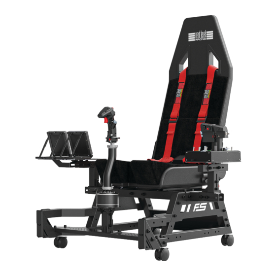
- Seite 1 T A K E I T T O T H E S K I E S Video Instruction: bit.ly/nlrbuild FLIGHT SEAT INSTRUCTION MANUAL *ELECTRONICS NOT INCLUDED...
- Seite 2 We know you’re eager to start flying! Take your time with the instructions and follow this guide to assemble your product. You’ll be setting yourself up for success by following the instruction booklet to fully optimize your product. ASSEMBLY VIDEO bit.ly/nlrbuild @next_level_racing @nextlevelracingOfficial @nextlvlracing Next Level Racing FOLLOW support@nextlevelracing.com...
- Seite 3 Video Instruction: bit.ly/nlrbuild T A K E I T T O T H E S K I E S N E X T L E V E L R A C I N G . C O M...
-
Seite 4: Pre-Flight Checks
support@nextlevelracing.com PRE-FLIGHT CHECKS WARNING • Please do not use power tools for assembly as over tightening can damage parts. • If you require further support, consult the installation video or contact us at support@nextlevelracing.com • Ensure all Castor Wheels are locked before sitting on the cockpit. •... - Seite 5 Video Instruction: bit.ly/nlrbuild IN THE *NOT TO SCALE (LEFT) (LEFT) (RIGHT) (RIGHT) 1 x LEFT FRAME MEMBER 1 x LEFT SIDE PANEL 1 x RIGHT FRAME MEMBER 1 x RIGHT SIDE PANEL 1 x FLIGHT PLATE 1 x MOUSE PLATE 1 x H FRAME 1 x SAFETY STEP 1 x CENTRE POLE BRACKET...
- Seite 6 support@nextlevelracing.com 1 x SEAT BOTTOM 1 x SEAT BACKREST 2 x MOTION V3 MOUNTING ARM 1 x SEAT BELT 5 x M8 20mm SOCKETHEAD BOLTS 56 x M8 16mm SOCKETHEAD BOLTS 16 x M6 16mm SOCKETHEAD BOLTS 1 x HOTAS EXTENSION BRACKET 16 x M5 16mm SOCKETHEAD BOLTS 5 x M8 16mm COUNTERSUNK BOLTS MOUNT...
-
Seite 7: Inhaltsverzeichnis
Video Instruction: bit.ly/nlrbuild KEY STEPS MOUNTING LOCATION DIAGRAMS page 8 Hotas Plate page 8 Flight Plate page 9 Mouse Plate page 10 GENERAL ASSEMBLY page 12 Extended HOTAS Mount Installation page 18 HOTAS Extension Mount Adjustment page 19 HOTAS Mount Installation page 19 Centre Pole Bracket Adjustment page 21... -
Seite 8: Mounting Location Diagrams
support@nextlevelracing.com MOUNTING LOCATIONS HOTAS PLATE PRODUCT LEGEND: TM HOTAS Warthog Stick / Winwing HOTAS Orion 2 VKB Gunfighter PRO MK.II Virpil Mongoos T-50CM3 with WarBRD Base Winwing Super Libra NOT TO SCALE... -
Seite 9: Flight Plate
Video Instruction: bit.ly/nlrbuild FLIGHT PLATE PRODUCT LEGEND: Logitech G X56 Throttle/HOTAS Logitech G X52 Throttle/HOTAS TMT.16000M / TCA Sidestick Airbus TM HOTAS Warthog Stick / Winwing HOTAS Orion 2 TM HOTAS Warthog Duel Throttle / Winwing Orion 2 Throttle TM TCA Quadrant Airbus Edition Throttle TM TCA Throttle Quadrant Boeing Edition TM TWCS Throttle Turtle Beach VelocityOne Flightstick... -
Seite 10: Mouse Plate
support@nextlevelracing.com MOUSE PLATE PRODUCT LEGEND: Virtual Fly TQ6+ Logitech G X56 Throttle/HOTAS Virtual Fly V3RNIO+ Logitech G X52 Throttle/HOTAS VKB Gladiator NXT TM 16000M / TCA Sidestick Airbus VKB Gunfighter PRO MK.II TM HOTAS Warthog Stick / Winwing HOTAS Orion 2 Virpil Mongoos T-50CM3 with WarBRD Base TM HOTAS Warthog Duel Throttle / Winwing Orion 2 Throttle Virpil Mongoos T-50CM3 Throttle... - Seite 11 Video Instruction: bit.ly/nlrbuild ADJUSTMENT POINTS The Flight Seat Pro is a fully adjustable cockpit making it perfect for flight enthusiasts of all sizes. Utilize the various adjustment points to achieve your desired position. FLIGHT SEAT MOUSE PLATE FLIGHT PLATE HOTAS PLATE...
-
Seite 12: General Assembly
support@nextlevelracing.com PARTS: • • 1 x Left Frame Member • • 1 x Right Frame Member (LEFT) (RIGHT) • • 1 x End Panel • • 4 x M8 55mm Sockethead Bolts Repeat • • 4 x M8 Washers on Other Side A) Align the Left and Right Frame Members with the threaded inserts on the End Panel. -
Seite 13: Bottom View
Video Instruction: bit.ly/nlrbuild PARTS: • • 1 x H Frame • • 4 x M8 55mm Sockethead Bolts Repeat on Other • • 4 x M8 Washers Side A) Align the threaded inserts on the H Frame with the mounting holes on the Frame Members. B) Bolt through and secure with 2 x M8 Bolts and Washers. - Seite 14 support@nextlevelracing.com PARTS: • • 1 x Seat Bottom • • 1 x Seat Backrest WARNING: Ensure you are firmly holding the Recliner before lifting the adjustment lever to avoid injury. A) Uninstall the pre-installed Bolts on the Seat Backrest. B) Adjust the Seat Recliners on the Seat Bottom to an upright position. PARTS: •...
- Seite 15 Video Instruction: bit.ly/nlrbuild PARTS: • • 2 x M8 16mm Sockethead Bolts • • 2 x M8 Washers A) Slide the Flight Seat all the way back to access the front mounting holes on the Seat Sliders. B) Bolt through and secure with 2 x M8 Bolts and Washers. PARTS: •...
- Seite 16 support@nextlevelracing.com PARTS: • • 1 x Telescoping Inner Arm • • 2 x M8 16mm Sockethead Bolts • • 2 x M8 Washers A) Align the threaded inserts on the Telescopic Inner Arm with the mounting slot on the Telescoping Outer Arm. B) Bolt through and secure with 2 x M8 Bolts and Washers.
- Seite 17 Video Instruction: bit.ly/nlrbuild PARTS: • • 1 x Telescoping Outer Arm • • 4 x M8 16mm Sockethead Bolts • • 4 x M8 Washers A) Align the mounting slots on the Telescoping Outer Arm with the threaded inserts on the Flight Arm. B) Bolt through and secure with 4 x M8 Bolts and Washers.
-
Seite 18: Extended Hotas Mount Installation
support@nextlevelracing.com PARTS: • • 2 x Plastic Caps Align the Plastic Caps with the Bolt cut-outs on the Frame Members and press them on to fit. PARTS: EXTENDED HOTAS MOUNT INSTALLATION (RECOMMENDED FOR EXTENDED HOTAS STICKS) • • 1 x HOTAS Extension Mount •... -
Seite 19: Hotas Extension Mount Adjustment
Video Instruction: bit.ly/nlrbuild PARTS: • • 4 x M8 16mm Sockethead Bolts • • 4 x M8 Washers Align the mounting slots on the HOTAS Extension Adjustment Bracket assembly with the threaded inserts on the HOTAS Extension Mount. Bolt through and secure with 4 x M8 Bolts and Washers. PARTS: HOTAS EXTENSION MOUNT ADJUSTMENT •... - Seite 20 support@nextlevelracing.com PARTS: • • 1 x Centre Pole Bracket • • 1 x M8 60mm Sockethead Bolt • • 2 x M8 12mm Knobs • • 3 x M8 Washers • • 1 x M8 Ny-lock Nut A) Align the mounting holes on the Centre Pole Bracket with the mounting slots and inserts on the Centre Pole Mount. B) Bolt through and secure with 2 x M8 Knobs and Washers &...
-
Seite 21: Centre Pole Bracket Adjustment
Video Instruction: bit.ly/nlrbuild PARTS: CENTRE POLE BRACKET ADJUSTMENT • • NIL A) Loosen the Knobs securing the Centre Pole Bracket to the Centre Pole Mount. B) Adjust to the desired angle and tighten the Knobs to secure. PARTS: HOTAS ANGLE ADJUSTMENT •... -
Seite 22: Flight Simulator Pro Setup
support@nextlevelracing.com FLIGHT SIMULATOR PRO SETUP... - Seite 23 Uninstall 2 x Rear Castor Wheels and Square Washers from the Flight Stand Pro Assembly. PARTS: • • NIL A) Uninstall 4 x Bolts and Washers securing the Steel Safety Caps to the Flight Seat Pro Frame. Remove the Plastic Caps. B) Uninstall the 2 x Steel Safety Caps.
- Seite 24 PARTS: • • NIL Align the slots on the Frame of the Flight Seat Pro to the threaded inserts on the Frame of the Flight Stand Pro. PARTS: • • NIL Repeat on Other Side Bolt through and secure with Bolts and Washers previously uninstalled in Step 33a. Repeat on the other side.
-
Seite 25: Seat Belt Installation
Video Instruction: bit.ly/nlrbuild PARTS: • • NIL Re-install Plastic Caps previously uninstalled in Step 33a. PARTS: SEAT BELT INSTALLATION • • 1 x Seat Belt A) Slide the Seat all the way backwards. B) Thread the Seat Belt through Seat Belt cut outs on the Flight Seat. PARTS: •... - Seite 26 support@nextlevelracing.com PARTS: • • NIL Repeat on Other Side A) Uninstall 2 x M8 Bolts and Washers securing the H Frame to the Frame. B) Align the Seat Belt end plates to the mounting holes on the Frame. PARTS: • • NIL Repeat on Other Side...
-
Seite 27: Motion Plus Platform Installation
Video Instruction: bit.ly/nlrbuild MOTION PLUS PLATFORM INSTALLATION PARTS: LOWER FLIGHT ARM ASSEMBLY (RECOMMENDED FOR COLLECTIVES) • • NIL Uninstall the Bolts and Washers securing the Flight Arm Assembly to the Frame and remove it. PARTS: • • NIL A) Align the mounting holes on the Flight Arm Assembly with the threaded inserts on the bottom rail of the Frame. B) Bolt through and secure with 2 x M8 Bolts and Washers previously uninstalled in Step 43. - Seite 28 support@nextlevelracing.com PARTS: • • NIL Align the threaded inserts on the Motion Plus Platform with the mounting holes on the Frames. PARTS: • • 2 x M8 55mm Sockethead Bolts • • 2 x M8 60mm Sockethead Bolts • • 4 x M8 Washers M8 60mm Repeat M8 55mm...
-
Seite 29: Buttkicker Pole Installation
Video Instruction: bit.ly/nlrbuild PARTS: BUTTKICKER POLE INSTALLATION (SKIP TO STEP 44 FOR MOTION V3 PLATFORM INSTALLATION) • • 1 x Buttkicker Pole • • 2 x M8 60mm Sockethead Bolts • • 2 x M8 Washers Note: The Buttkicker pole can be •... - Seite 30 support@nextlevelracing.com PARTS: • • NIL WARNING: The NLR Motion V3 is heavy and will require 2 people to install the setup. Align the Motion V3 unit with the mounting holes on the Frame. PARTS: • • 6 x M8 55mm Sockethead Bolts •...
-
Seite 31: Seat Belt Installation
Video Instruction: bit.ly/nlrbuild PARTS: • • 4 x M8 16mm Sockethead Bolts • • 4 x M8 Washers A) Bolt through the front mounting holes of the Motion V3 platform and secure with 2 x M8 Bolts and Washers. B) Bolt through the rear mounting holes of the Motion V3 platform and secure with 2 x M8 Bolts and Washers. PARTS: SEAT BELT INSTALLATION Repeat... - Seite 32 support@nextlevelracing.com PARTS: • • NIL Install the HOTAS Mount Assembly to the H Frame. Please refer to Step 24 to 27 for HOTAS Mount Assembly. PARTS: • • 8 x M8 16mm Sockethead Bolts • • 8 x M8 Washers Repeat on Other Side...
-
Seite 33: Flight Arm Adjustment
Video Instruction: bit.ly/nlrbuild PARTS: FLIGHT ARM ADJUSTMENT • • NIL Front View Loosen the Bolts on the Flight Arm Assembly, adjust to the desired position and tighten the Bolts to secure. PARTS: FLIGHT/MOUSE PLATE ADJUSTMENT • • NIL Side View Loosen Bolts securing the Flight Plate to the Flight Arm Assembly. - Seite 34 FLIGHT SEAT PRO ENTRY LEVEL UPGRADE PATH NLR HF8 Haptic Gaming Pad NLR Free Standing Keyboard & Mouse Stand NLR Lite Free Standing Monitor Stand NLR Floor Mat...
- Seite 35 Video Instruction: bit.ly/nlrbuild FLIGHT SEAT PRO ADVANCED UPGRADE PATH NLR Flight Stand Pro NLR Free Standing Keyboard & Mouse Stand NLR Free Standing Triple Monitor Stand NLR Floor Mat NLR Motion Plus Platform NLR Motion Platform V3...
- Seite 36 support@nextlevelracing.com WARNING Please do not use power tools for assembly as over tightening can damage parts. If you require further support, consult the installation video or contact us at support@nextlevelracing.com Ensure all Castor Wheels are locked before sitting on the cockpit. Do not force parts together.
- Seite 37 32 – Reportez-vous à l’image. Désinstallez les 2 roues pivotantes arrière et les rondelles carrées de l’ensemble Flight Stand Pro. 33 – Reportez-vous à l’image. A) Désinstallez 4 boulons et rondelles fixant les capuchons de sécurité en acier au cadre Flight Seat Pro. Retirez les capuchons en plastique. B) Désinstallez les 2 capuchons de sécurité en acier.
- Seite 38 32 – Zie afbeelding. Verwijder 2 achterste zwenkwielen en vierkante ringen van de Flight Stand Pro-constructie. 33 – Zie afbeelding. A) Verwijder de 4 x bouten en ringen waarmee de stalen veiligheidskappen aan het frame van de Flight Seat Pro zijn bevestigd. Verwijder de plastic doppen. B) Verwijder de 2 x stalen veiligheidskappen.
- Seite 39 33 – Fare riferimento all’immagine. A) Disinstallare i 4 bulloni e le rondelle che fissano i cappucci di sicurezza in acciaio al telaio Flight Seat Pro. Rimuovere i tappi di plastica. B) Disinstallare i 2 tappi di sicurezza in acciaio.
- Seite 40 32 – Consulte la imagen. Desinstale las 2 ruedas giratorias traseras y las arandelas cuadradas del ensamblaje Flight Stand Pro. 33 – Consulte la imagen. A) Desinstale los 4 pernos y arandelas que sujetan las tapas de seguridad de acero al armazón Flight Seat Pro. Retire las tapas de plástico. B) Desinstale las 2 tapas de seguridad de acero.
- Seite 41 32 – Siehe Bild. Deinstallieren Sie 2 x hintere Lenkrollen und quadratische Unterlegscheiben von der Flight Stand Pro-Baugruppe. 33 – Siehe Bild. A) Entfernen Sie 4 x Schrauben und Unterlegscheiben, mit denen die Stahlsicherheitskappen am Rahmen des Flight Seat Pro befestigt sind. Entfernen Sie die Plastikkappen. B) Entfernen Sie die 2 x Sicherheitskappen aus Stahl.
- Seite 42 30 – 画像を参照して ください。 1) 肩が露出して自由に動けるようになるまで、 肩ボルトを緩めます。 M8ボルトを緩めて動かせるようにします。 2) 希望の高さに調整し、 M8 ボルトとショルダーボルトの両方を締めて固定します。 31 – 画像を参照して ください。 A) スイベル フライ ト アーム アセンブリと HOTAS センター ポール アセンブリを Flight Stand Pro のフレームから取り外します。 B) Flight Seat Pro のフレームからマウス プレート アセンブリと HOTAS センター ポール アセンブリを取り...
- Seite 43 32 – Consulte a imagem. Desinstale 2 rodas giratórias traseiras e arruelas quadradas do conjunto Flight Stand Pro. 33 – Consulte a imagem. A) Desinstale 4 parafusos e arruelas que prendem as tampas de segurança de aço à estrutura do Flight Seat Pro. Remova as tampas plásticas. B) Desinstale as 2 tampas de segurança de aço.
- Seite 44 болт с буртиком, чтобы зафиксировать. 31 – См. изображение. A) Снимите сборку поворотного кронштейна и сборку центральной стойки HOTAS с рамы стенда Flight Stand Pro. B) Снимите узел пластины для мыши и узел центральной стойки HOTAS с рамы кресла Flight Seat Pro.
- Seite 45 31 – Resme bakın. A) Döner Uçuş Kolu Tertibatını ve HOTAS Merkez Direk Tertibatını Flight Stand Pro Çerçevesinden çıkarın. B) Fare Plakası Tertibatını ve HOTAS Merkez Direk Tertibatını Flight Seat Pro Çerçevesinden çıkarın. 32 – Resme bakın. Flight Stand Pro Tertibatından 2 x Arka Küçük Tekerleği ve Kare Pulları çıkarın.
- Seite 46 30 – Viz obrázek. 1) Povolte ramenní šroub, dokud nebude rameno odhaleno a volně se pohybovat. Uvolněte šrouby M8, abyste umožnili pohyb. 2) Nastavte na požadovanou výšku a utáhněte šroub M8 i ramenní šroub pro zajištění. 31 – Viz obrázek. A) Odmontujte sestavu otočného letového ramene a sestavu středové tyče HOTAS z rámu stojanu Pro. B) Odmontujte sestavu desky myši a sestavu středové tyče HOTAS z rámu sedadla Flight Seat Pro.
- Seite 47 30 – Patrz obraz. 1) Poluzuj śrubę pasowaną, aż ramię będzie odsłonięte i będzie mogło się swobodnie poruszać. Poluzuj śruby M8, aby umożliwić ruch. 2) Ustaw żądaną wysokość i dokręć zarówno śrubę M8, jak i śrubę pasowaną, aby zabezpieczyć. 31 – Patrz obraz. A) Zdemontuj zespół ramienia obrotowego i zespół słupka środkowego HOTAS z ramy Flight Stand Pro. B) Zdemontuj zespół płytki myszy i zespół słupka środkowego HOTAS z ramy siedziska Flight Seat Pro.
- Seite 48 31 - زكرم دومع ةعومجمو ، راودلا ناريطلا عارذ ةعومجم تيبثت ءاغلإب مق )أ .ةروصلا ىلإ عوجرلاHOTAS راطإ نمFlight Stand Pro. زكرم دومع ةعومجمو ، سواملا ةحول ةعومجم تيبثت ءاغلإب مق )بHOTAS راطإ نمFlight Seat Pro.
- Seite 49 30 – 参考图像。 1) 松开肩部螺栓, 直到肩部露出并可以自由移动。 松开 M8 螺栓以允许移动。 2) 调整到所需高度并拧紧 M8 螺栓和带肩螺栓以固定。 31 – 参考图像。 A) 从 Flight Stand Pro 的框架上卸下旋转飞行臂组件和 HOTAS 中心杆组件。 B) 从 Flight Seat Pro 框架上卸下鼠标板组件和 HOTAS 中心杆组件。 32 – 参考图像。 从 Flight Stand Pro 组件上卸下 2 个后脚轮和方形垫圈。...
- Seite 50 support@nextlevelracing.com support@nextlevelracing.com...