Herunterladen Inhalt Inhalt Diese Seite drucken
Inhaltsverzeichnis

Werbung

Verfügbare Sprachen

Verfügbare Sprachen

ENGLISH
DEUTSCH
FRANÇAIS
Mounting Instructions
Montageanleitung
Notice de montage
MCS10

Werbung

Inhaltsverzeichnis
loading

Inhaltszusammenfassung für HBK MCS10

  • Seite 1 ENGLISH DEUTSCH FRANÇAIS Mounting Instructions Montageanleitung Notice de montage MCS10...
  • Seite 2 Hottinger Brüel & Kjaer GmbH Im Tiefen See 45 D-64293 Darmstadt Tel. +49 6151 803-0 Fax +49 6151 803-9100 info@hbkworld.com www.hbkworld.com Mat.: 7-0111.0015 DVS: A04466 05 Y00 03 07.2022 E Hottinger Brüel & Kjaer GmbH Subject to modifications. All product descriptions are for general information only.
  • Seite 3: Mounting Instructions

    ENGLISH DEUTSCH FRANÇAIS Mounting Instructions MCS10...
  • Seite 4: Inhaltsverzeichnis

    ........... . 12.3 MCS10-010-3C, MCS10-025-3C, MCS10-050-3C ......
  • Seite 5 12.5 MCS10-100-3C ........... .
  • Seite 6: Safety Instructions

    SAFETY INSTRUCTIONS Appropriate use The MCS10 multicomponent sensor is used to measure up to six loads, such as axial force Fz, lateral forces Fx, Fy, bending moments Mx, My, and torsional moment Mz, in the positive and negative signal direction. Although this only applies in the context of the range stated in the specifications.
  • Seite 7 3. As commissioning engineers or service engineers, they have successfully completed the training to qualify them to repair the automation systems. They are also authorized to operate, ground and label circuits and equipment in accordance with safety engineering stan­ dards. MCS10 SAFETY INSTRUCTIONS...
  • Seite 8: Scope Of Supply

    SCOPE OF SUPPLY Sensor in accordance with the ordering code Test certificate of the individual components for the positive signal direction Mounting instructions MCS10 SCOPE OF SUPPLY...
  • Seite 9: Markings Used

    CE mark The CE mark enables the manufacturer to guarantee that the product complies with the requirements of the relevant EU direc­ tives (the EU declaration of conformity can be found on the HBK website at www.hbm.com). MCS10 MARKINGS USED...
  • Seite 10 Ö GB/T Å 。 26572 X: Indicates that said hazardous substance contained in at least one of the homoge­ neous materials used for this part is above the limit requirement of GB/T 26572. Ö GB/T 。 26572 MCS10 MARKINGS USED...
  • Seite 11: Application

    The housing protects the application from moisture and various media. No load or force may be applied to the sensor via the housing. The MCS10 multicomponent sensor is reliably protected against electromagnetic inter­ ference. It has been tested in accordance with harmonized European standards. The product carries the CE mark.
  • Seite 12: Structure And Mode Of Operation

    STRUCTURE AND MODE OF OPERATION The MCS10 multicomponent sensor is designed with a monolithic measuring body on which strain gages (SG) are installed. The measuring body is enclosed in a housing. On the housing is a terminal box with connector plugs for the measuring bridge power supply and transferring output signals.
  • Seite 13: Mechanical Installation

    Protect the transducer from weather conditions such as rain, snow, ice, and salt water. Ambient temperature There is wide ranging compensation for the effects of temperature on the zero signal and on sensitivity (see the “Specifications” chapter, starting on page 40). To obtain optimum MCS10 MECHANICAL INSTALLATION...
  • Seite 14: Mounting The Sensor

    = 0.125), permitted size and shape variance as per DIN ISO 4759, Part 1, product class A. 3. Fasten all screws with the specified torque (see Tab. 6.1). Fit the screws by tightening them diagonally in two steps (50% and 100% of the full tightening torque). MCS10 MECHANICAL INSTALLATION...
  • Seite 15: Measurement Range

    → Positioning pin Please use the centering pin for positioning and aligning the load application/mounting parts to the sensor. Fig. 6.1 Mechanical interface description Measurement MCS10-005 MCS10-010 MCS10-025 MCS10-100 MCS10-200 range & -050 Centering Ø30 H8 Ø45 H8 Ø45 H8 Ø60 H8...
  • Seite 16: Quality Of The Customer's Own Attachment Parts

    Table 1, as this affects the coefficient of friction. Quality of the customer's own attachment parts The customers' own attachment parts (contact surfaces) must meet the following condi­ tions to achieve optimum and repeatable measurement results: MCS10 MECHANICAL INSTALLATION...
  • Seite 17: Recommended Fits For The Customer's Own Attachment Parts

    They must be made of steel and have a minimum hardness of 40HRC. For types MCS10-005 and MCS10-010, a titanium customer-side construction is also possible. The hardness of the stainless steel transducer body is at least 42HRC for steel and about 30HRC for titanium.
  • Seite 18: Mounting Position And Force Application

    In the three-dimensional coordinate system, the so-called right-hand rule clearly defines the orientation of the three force directions and the moments rotating clockwise around the axes of the positive force directions (also see Fig. 6.5). Fig. 6.5 Right-hand rule MCS10 MECHANICAL INSTALLATION...
  • Seite 19 If the forces are applied in the application in such a way that they do not go through the point of origin, the moments that are then generated (force times lever arm) must be observed (see Fig. 6.7). MCS10 MECHANICAL INSTALLATION...
  • Seite 20 The maximum permitted loads stated in the specifications must be complied with, even if measurement is not taking place in individual axes. Sensor height [mm] Tab. 6.2 Sensor heights MCS10 MECHANICAL INSTALLATION...
  • Seite 21: Crosstalk

    Fx, Fy, Fz, and the moments Mx, My and Mz. If a single load is applied, e.g. the axial force Fz, the other measuring bridges will output a very small signal. This unwanted signal is called crosstalk. MCS10 CROSSTALK...
  • Seite 22: Electrical Connection

    All cable plug connections or swivel nuts must be properly connected. Important Transducer connection cables from HBK with fitted plugs are marked in accordance with their intended purpose. When cables are shortened, inserted into cable ducts or installed in control cabinets, this marking can be lost or hidden. Mark the cables before laying them in this case.
  • Seite 23: Pin Assignment

    In order to avoid interference coupling, please note the following information: Use shielded, low-capacitance measurement cables only (HBK cables fulfill both con­ ditions). Only use plugs that meet EMC guidelines.
  • Seite 24 PIN 2: Bridge excitation voltage (+) bu (blue) PIN 3: Sense lead (+) gn (green) PIN 5: Sense lead (-) (TEDS optional) gy (gray) Cable shield, connected to the Shield housing Fig. 8.1 Pin assignment for the 6-wire configuration MCS10 ELECTRICAL CONNECTION...
  • Seite 25: Teds Transducer Identification

    PIN 5 and PIN 6. Its content can be edited and modified with suitable hardware and software. The Quantum Assistant, or DAQ CATMAN software from HBK, can be used for this purpose, for example. Please pay attention to the operating manuals of these products.
  • Seite 26: Maintenance

    MAINTENANCE MCS10 multicomponent sensors are maintenance free. MCS10 MAINTENANCE...
  • Seite 27: Waste Disposal & Environmental Protection

    Packaging The original packaging of HBK devices is made from recyclable material and can be sent for recycling. Store the packaging for at least the duration of the warranty. In the case of complaints, the multicomponent sensor must be returned in the original packaging.
  • Seite 28: Dimensions

    DIMENSIONS 12.1 MCS10-005-3C 45° 8 mm 30.033 Ø58 Ø30 H8 30.000 0.03 B 25±0.1 0.02 A Maximum centering depth 25±0.1 30.033 Ø30 H8 30.000 45° (4x) 22.5° (4x) 22.5° (4x) 8 mm MCS10 DIMENSIONS...
  • Seite 29: Mcs10-005-6C

    12.2 MCS10-005-6C 45° 8 mm 30.033 Ø58 Ø30 H8 30.000 0.03 B 25±0.1 0.02 A Maximum centering depth 25±0.1 30.033 Ø30 H8 30.000 45° (4x) 22.5° (4x) 22.5° (4x) 8 mm MCS10 DIMENSIONS...
  • Seite 30: Mcs10-010-3C, Mcs10-025-3C, Mcs10-050-3C

    12.3 MCS10-010-3C, MCS10-025-3C, MCS10-050-3C 45° 11 mm Ø86 45.039 Ø45 H8 45.000 0.03 B 35±0.1 0.02 A Maximum centering depth 35±0.1 45.039 Ø45 H8 45.000 45° (4x) 22.5° (4x) 22.5° (4x) 11 mm MCS10 DIMENSIONS...
  • Seite 31: Mcs10-010-6C, Mcs10-025-6C, Mcs10-050-6C

    12.4 MCS10-010-6C, MCS10-025-6C, MCS10-050-6C 45° 11 mm 45.039 Ø86 Ø45 H8 45.000 0.03 B 35±0.1 0.02 A Maximum centering depth 35±0.1 45.039 Ø45 H8 45.000 45° (4x) 22.5° (4x) 22.5° (4x) 11 mm MCS10 DIMENSIONS...
  • Seite 32: Mcs10-100-3C

    12.5 MCS10-100-3C 45° 14 mm 60.046 Ø111 Ø60 H8 60.000 0.03 B 45±0.1 0.02 A Maximum centering depth 45±0.1 60.046 Ø60 H8 60.000 45° (4x) 22.5° (4x) 22.5° (4x) 14 mm MCS10 DIMENSIONS...
  • Seite 33: Mcs10-100-6C

    12.6 MCS10-100-6C 45° 14 mm 60.046 Ø111 Ø60 H8 60.000 0.03 B 45±0.1 0.02 A Maximum centering depth 45±0.1 60.046 Ø60 H8 60.000 45° (4x) 22.5° (4x) 22.5° (4x) 14 mm MCS10 DIMENSIONS...
  • Seite 34: Mcs10-200-3C

    12.7 MCS10-200-3C 45° 16 mm 60.046 Ø111 Ø60 H8 60.000 0.03 B 45±0.1 0.02 A Maximum centering depth 45±0.1 60.046 Ø60 H8 60.000 45° (4x) 25° (4x) 25° (4x) 16 mm MCS10 DIMENSIONS...
  • Seite 35: Mcs10-200-6C

    12.8 MCS10-200-6C 45° 16 mm 60.046 Ø111 Ø60 H8 60.000 0.03 B 45±0.1 0.02 A Maximum centering depth 45±0.1 60.046 Ø60 H8 60.000 45° (4x) 25° (4x) 25° (4x) 16 mm MCS10 DIMENSIONS...
  • Seite 36: Cable Outlet For A Three-Component Transducer

    12.9 Cable outlet for a three-component transducer 13.5 44.5 12.10 Cable outlet for a six-component transducer 44.5 13.5 MCS10 DIMENSIONS...
  • Seite 37: 12.11 Cable Connection

    12.11 Cable connection MCS10 DIMENSIONS...
  • Seite 38: Ordering Number And Accessories

    ORDERING NUMBER AND ACCESSORIES 13.1 Ordering number MSC10 Ordering number K‐MCS10 Code Option 1: Measurement range =1 kN; F =1 kN; F =5 kN; M =0.05 kNm; M =0.05 kNm; =0.05 kNm =2 kN; F =2 kN; F =10 kN; M =0.15 kNm;...
  • Seite 39 Without TEDS chip With TEDS chip For example: K-MCS10 - 0 1 0 - 6 C - F X - F Y - 0 0 - M X - 0 0 - M Z - S MCS10 ORDERING NUMBER AND ACCESSORIES...
  • Seite 40: Connection Cable K-Kab-M And 1-Kab146

    (blue) PIN 2: Bridge excitation voltage (+) U PIN 3: Sense lead (+) gn (green) gy (gray) PIN 5: Sense lead (-) (TEDS optional) Cable shield, connected to the Shield housing Fig. 13.1 Pin assignment MCS10 ORDERING NUMBER AND ACCESSORIES...
  • Seite 41 Ordering numbers K-KAB-M Ordering number K‐KAB-M Code Option 1: Cable type 0228 6-wire cable, TPE, Ø4.8 mm, gray, for MCS10 0151 6-wire cable, TPE-U, Ø3.8 mm, suitable for drag chains, black for MCS10 Code Option 2: Sensor side connection Lemo plug type 0T, 6-pin straight, for MCS10...
  • Seite 42: Specifications

    <±0.05 tivity Rel. reversibility error (0.2F to F ), related to nominal sensitivity Forces (F & F <±0.1 U (d Moments (M & M <±0.15 <±0.1 <±0.15 Rel. creep over 30 mins. <±0.15 crF+E MCS10 SPECIFICATIONS...
  • Seite 43 Storage temperature °C -30 to +85 range Reference temperature °C The individual sensitivity can be found in the test certificate and, as an option, can be stored in the TEDS chip. This sensitivity has a maximum deviation of 0.5% MCS10 SPECIFICATIONS...
  • Seite 44 ; y,nom My->Mx Torsional moment Mz->Mx <±1.5 <±1 z,nom Mz->My Axial force (F <±3 <±1.5 z,nom Fz->Mz Lateral force (F Torsional x,nom; Fx->Mz <±3 <±1 moment y,nom Fy->Mz z,nom Bending moment Mx->Mz <±1.5 <±1 x,nom ; y,nom My->Mz MCS10 SPECIFICATIONS...
  • Seite 45 Lateral force limit (Fx, Fy), related x(y),L to F y,nom Axial force limit (Fz), related to Bending moment limit (Mx, My), x(y),L related to M x,nom y,nom Torsional moment limit (Mz), related to M z,nom MCS10 SPECIFICATIONS...
  • Seite 46 <0.05 <0.05 <0.06 <0.05 <0.05 x,nom y,nom Torsion angle at M degrees <0.08 <0.08 <0.06 <0.07 <0.08 <0.07 z,nom Stiffness in the radial direction kN/mm (x or y) Stiffness in the axial direction (z) kN/mm 1664 3018 4824 MCS10 SPECIFICATIONS...
  • Seite 47 Section 7) RFI field strength Class B Immunity to interference (EN 61326-1, Table 2; EN 61326-2-3) Electromagnetic fields (AM) Power-frequency magnetic fields Electrostatic discharge (ESD) Contact discharge Air discharge Fast transients (burst) Impulse voltages (surge) Conducted interference (AM) MCS10 SPECIFICATIONS...
  • Seite 48 The relevant natural frequency of the overall setup changes naturally if additional masses are mounted on the transducer. Consequently, this is a recommended value serving as a guide, which always requires consideration of the mounting conditions for a dynamic setup. MCS10 SPECIFICATIONS...
  • Seite 49 ENGLISH DEUTSCH FRANÇAIS Montageanleitung MCS10...
  • Seite 50 ..........MCS10...
  • Seite 51 ........... . 12.3 MCS10-010-3C, MCS10-025-3C, MCS10-050-3C ......
  • Seite 52: Sicherheitshinweise

    SICHERHEITSHINWEISE Bestimmungsgemäße Verwendung Der Mehrkomponentenaufnehmer MCS10 ist für Messungen von bis zu sechs Lasten wie der Axialkraft Fz, den Querkräften Fx, Fy, den Biegemomenten Mx, My, sowie des Tor­ sionsmoments Mz, in positiver und negativer Signalrichtung, zu verwenden. Dies gilt allerdings nur im Rahmen des durch die technischen Daten spezifizierten Bereichs.
  • Seite 53 Betrieb des Produktes vertraut sind und die über die ihrer Tätigkeit entsprechende Quali­ fikationen verfügen. Dazu zählen Personen, die mindestens eine der drei folgenden Voraussetzungen erfüllen: 1. Ihnen sind die Sicherheitskonzepte der Automatisierungstechnik bekannt und sie sind als Projektpersonal damit vertraut. MCS10 SICHERHEITSHINWEISE...
  • Seite 54 3. Sie sind Inbetriebnehmer oder für den Service eingesetzt und haben eine Ausbildung absolviert, die sie zur Reparatur der Automatisierungsanlagen befähigt. Außerdem haben sie eine Berechtigung, Stromkreise und Geräte gemäß den Normen der Sicherheitstechnik in Betrieb zu nehmen, zu erden und zu kennzeichnen. MCS10 SICHERHEITSHINWEISE...
  • Seite 55: Lieferumfang

    LIEFERUMFANG Aufnehmer gemäß Bestellcode Prüfprotokoll der Einzelkomponenten für die positive Signalrichtung Montageanleitung MCS10 LIEFERUMFANG...
  • Seite 56: Verwendete Kennzeichnungen

    Auf dem Aufnehmer verwendete Symbole Angaben in dieser Anleitung nachlesen und berücksichtigen CE-Kennzeichnung Mit der CE-Kennzeichnung garantiert der Hersteller, dass sein Produkt den Anforderungen der relevanten EU-Richtlinien ent­ spricht (die EU-Konformitätserklärung finden Sie auf der Website von HBK unter www.hbm.com). MCS10 VERWENDETE KENNZEICHNUNGEN...
  • Seite 57 Baugruppe geringer als der Grenzwert laut GB/T 26572 ist. Ö GB/T 26572 Å 。 X: Bedeutet, dass mindestens einer der betreffende gefährliche Stoff innerhalb der homogenen Stoffe der Baugruppe oberhalb des Grenzwerts laut GB/T 26572 ist. Ö GB/T 26572 。 MCS10 VERWENDETE KENNZEICHNUNGEN...
  • Seite 58: Anwendung

    Das Gehäuse schützt die Applikation vor Feuchtigkeit und diversen Medien. Über das Gehäuse darf keine Last bzw. Kraft in den Aufnehmer eingeleitet werden. Der Mehrkomponentenaufnehmer MCS10 verfügt über einen zuverlässigen Schutz vor elektromagnetischen Störungen. Er wurde gemäß harmonisierten europäischen Normen getestet.
  • Seite 59: Aufbau Und Wirkungsweise

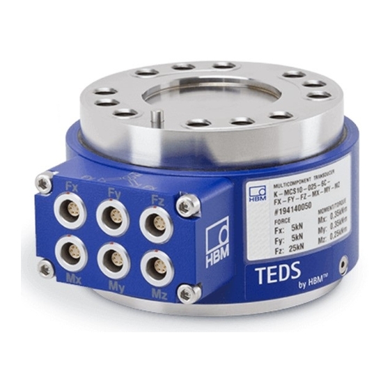
    AUFBAU UND WIRKUNGSWEISE Bei dem Mehrkomponentenaufnehmer MCS10 handelt es sich um einen monolithisch aufgebauten Messkörper, auf welchem Dehnungsmessstreifen (DMS) installiert sind. Der Messkörper ist durch ein Gehäuse abgeschlossen. Am Gehäuse befindet sich ein Steckerkasten mit Anschlusssteckern für die Spannungsversorgung der Messbrücken und die Übertragung der Ausgangssignale.
  • Seite 60: Mechanischer Einbau

    Ist der bleibende Nullpunktversatz im ausgebauten Zustand größer als 1% vom Kennwert senden Sie den Aufnehmer bitte zur Prüfung ins Werk Darmstadt. Bedingungen am Einbauort Schützen Sie den Aufnehmer vor Witterungseinflüssen wie beispielsweise Regen, Schnee, Eis und Salzwasser. MCS10 MECHANISCHER EINBAU...
  • Seite 61: Montage Des Aufnehmers

    =0,125), zulässige Maß- und Formabweichung nach DIN ISO 4759, Teil1, Produktklasse A. 3. Ziehen Sie alle Schrauben mit dem vorgeschriebenen Drehmoment an (siehe Tab. 6.1). Montieren Sie die Schrauben über Kreuz in zwei Stufen (50% und 100% des vollen Anzugsmoments). MCS10 MECHANISCHER EINBAU...
  • Seite 62: Messbereich

    → Positionierstift Bitte nutzen Sie die Zentrierstifte für die Positionierung und Ausrichtung der Lasteinleitungs-/Befestigungsteile auf den Aufnehmer. Abb. 6.1 Beschreibung der mechanischen Schnittstelle Messbereich MCS10-005 MCS10-010 MCS10-025 MCS10-100 MCS10-200 und -050 Zentrierung Ø30 H8 Ø45 H8 Ø45 H8 Ø60 H8 Ø60 H8...
  • Seite 63: Beschaffenheit Der Kundeneigenen Anbauteile

    Anzugsmomente können sich auch ändern, falls Sie Schrauben mit anderer Oberfläche oder anderer Festigkeitsklasse als in Tab. 1 angegeben verwenden, da dies den Reibfaktor beeinflusst. Beschaffenheit der kundeneigenen Anbauteile Die kundeneigenen Anbauteile (Auflageflächen) sollten folgende Bedingungen erfüllen, um optimale, wiederholbare Messergebnisse zu erreichen: MCS10 MECHANISCHER EINBAU...
  • Seite 64: Passungsempfehlungen Für Die Kundeneigenen Anbauteile

    Sie müssen lackfrei sein. Sie sollten aus Stahl sein und eine Härte von mindestens 40HRC aufweisen. Bei den Typen MCS10-005 und MCS10-010 ist auch eine kundenseitige Konstruktion aus Titan möglich. Der Edelstahlmesskörper des Aufnehmers hat eine Härte von mindestens 42HRC bei Stahl und von ca. 30HRC bei Titan.
  • Seite 65: Einbaulage Und Krafteinleitung

    Die Einbaulage des Mehrkomponentenaufnehmers wird durch die auf dem Steckerkasten angebrachten Pfeile vorgegeben. Werden die Kräfte und Momente in Pfeilrichtung einge­ leitet, liefern angeschlossene HBK-Messverstärker ein positives Ausgangssignal (siehe Kapitel 12 „Abmessungen“, Seite 27). Zur anschaulichen Bestimmung der Orientierung der drei Kraftrichtungen und der Momente, welche im Uhrzeigersinn um die Achsen der positiven Kraftrichtungen drehen, dient im dreidimensionalen Koordinatensystem die sogenannte Rechte-Hand-Regel (ver­...
  • Seite 66 Krafteinleitung weit vom Aufnehmer entfernt, kann das größer werdende Biegemoment die Messergebnisse der anderen Komponenten beeinflussen. Werden in der Anwendung die Kräfte so eingeleitet, dass sie nicht durch den Koordinatenursprung gehen, sind die dadurch auftretenden Momente (Kraft mal Hebelarm) zu beachten (siehe Abb. 6.7). MCS10 MECHANISCHER EINBAU...
  • Seite 67 Hebelarms die halbe Aufnehmerhöhe (vergleiche Tab. 6.2) berücksichtigt werden, da sich der Koordinatenursprung in der Mitte des Aufnehmers befindet. Die maximal zulässigen Lasten laut technischer Daten sind einzuhalten. Auch wenn in einzel­ nen Achsen nicht gemessen wird. Aufnehmerhöhe [mm] Tab. 6.2 Aufnehmerhöhen MCS10 MECHANISCHER EINBAU...
  • Seite 68: Übersprechen

    Sechskomponentenaufnehmer, der alle Freiheitsgrade beschreibt: die drei Kräfte Fx, Fy, Fz, sowie die Momente Mx, My und Mz. Unter Belastung einer einzelnen Last, z.B. der Axialkraft Fz, zeigen die übrigen Mess­ brücken ein sehr kleines Signal. Dieses unerwünschte Signal wird als Übersprechen bezeichnet. MCS10 ÜBERSPRECHEN...
  • Seite 69: Elektrischer Anschluss

    Alle Kabel-Steckverbindungen oder Überwurfmuttern müssen ordnungsgemäß ver­ bunden werden. Wichtig Aufnehmer-Anschlusskabel von HBK mit montierten Steckern sind ihrem Verwendungs­ zweck entsprechend gekennzeichnet. Beim Kürzen der Kabel, Einziehen in Kabelkanälen oder Verlegen in Schaltschränken kann diese Kennzeichnung verloren gehen oder verdeckt sein.
  • Seite 70: Hinweise Für Die Verkabelung

    Das geschieht insbesondere durch Erdung der Messkette an verschie­ denen Punkten, die nicht dasselbe Potenzial aufweisen. Um Einkopplungen von Störungen zu vermeiden beachten Sie bitte folgende Hinweise: Verwenden Sie nur abgeschirmte, kapazitätsarme Messkabel (HBK-Kabel erfüllen diese Bedingungen). Verwenden Sie ausschließlich Stecker, die den EMV-Richtlinien entsprechen.
  • Seite 71: Pinbelegung Für Die Sechsleiterschaltung

    PIN 4: Messsignal (-) U rt (rot) PIN 2: Brückenspeisespannung (+) U bl (blau) PIN 3: Fühlerleitung (+) gn (grün) PIN 5: Fühlerleitung (-) gr (grau) (optional: TEDS) Schirm Kabelschirm, verbunden mit Gehäuse Geh. Geh. Abb. 8.1 Pinbelegung für die Sechsleiterschaltung MCS10 ELEKTRISCHER ANSCHLUSS...
  • Seite 72: Aufnehmer-Identifikation Teds

    Steckeranschluss zwischen PIN 5 und PIN 6 zur Verfügung. Der Inhalt kann mit entspre­ chender Hard‐ und Software editiert und geändert werden. Hierzu kann z.B. der Quantum Assistent oder auch die DAQ Software CATMAN von HBK dienen. Bitte beachten Sie die Bedienungsanleitungen dieser Produkte.
  • Seite 73: Wartung

    WARTUNG Die Mehrkomponentenaufnehmer MCS10 sind wartungsfrei. MCS10 WARTUNG...
  • Seite 74: Entsorgung Und Umweltschutz

    Bedarfsfall Ihren Lieferanten anzusprechen, welche Art von Entsorgung oder Recycling in Ihrem Land vorgeschrieben ist. Verpackungen Die Originalverpackung der HBK-Geräte besteht aus recycelbarem Material und kann der Wiederverwertung zugeführt werden. Bewahren Sie die Verpackung jedoch mindestens für den Zeitraum der Gewährleistung auf. Bei Reklamationen muss der Mehr­...
  • Seite 75: Abmessungen

    ABMESSUNGEN 12.1 MCS10-005-3C 45° 30,033 Ø58 Ø30 H8 30,000 0,03 B 25±0,1 0,02 A maximale Zentriertiefe 25±0,1 30,033 Ø30 H8 30,000 45° (4x) 22,5° (4x) 22,5° (4x) MCS10 ABMESSUNGEN...
  • Seite 76: Mcs10-005-6C

    12.2 MCS10-005-6C 45° 30,033 Ø58 Ø30 H8 30,000 0,03 B 25±0,1 0,02 A maximale Zentriertiefe 25±0,1 30,033 Ø30 H8 30,000 45° (4x) 22,5° (4x) 22,5° (4x) MCS10 ABMESSUNGEN...
  • Seite 77: Mcs10-010-3C, Mcs10-025-3C, Mcs10-050-3C

    12.3 MCS10-010-3C, MCS10-025-3C, MCS10-050-3C 45° 11mm Ø86 45,039 Ø45 H8 45,000 0,03 B 35±0,1 0,02 A maximale Zentriertiefe 35±0,1 45,039 Ø45 H8 45,000 45° (4x) 22,5° (4x) 22,5° (4x) 11mm MCS10 ABMESSUNGEN...
  • Seite 78: Mcs10-010-6C, Mcs10-025-6C, Mcs10-050-6C

    12.4 MCS10-010-6C, MCS10-025-6C, MCS10-050-6C 45° 11mm 45,039 Ø86 Ø45 H8 45,000 0,03 B 35±0,1 0,02 A maximale Zentriertiefe 35±0,1 45,039 Ø45 H8 45,000 45° (4x) 22,5° (4x) 22,5° (4x) 11mm MCS10 ABMESSUNGEN...
  • Seite 79: Mcs10-100-3C

    12.5 MCS10-100-3C 45° 14mm 60,046 Ø111 Ø60 H8 60,000 0,03 B 45±0,1 0,02 A maximale Zentriertiefe 45±0,1 60,046 Ø60 H8 60,000 45° (4x) 22,5° (4x) 22,5° (4x) 14mm MCS10 ABMESSUNGEN...
  • Seite 80: Mcs10-100-6C

    12.6 MCS10-100-6C 45° 14mm 60,046 Ø111 Ø60 H8 60,000 0,03 B 45±0,1 0,02 A maximale Zentriertiefe 45±0,1 60,046 Ø60 H8 60,000 45° (4x) 22,5° (4x) 22,5° (4x) 14mm MCS10 ABMESSUNGEN...
  • Seite 81: Mcs10-200-3C

    12.7 MCS10-200-3C 45° 16mm 60,046 Ø111 Ø60 H8 60,000 0,03 B 45±0,1 0,02 A maximale Zentriertiefe 45±0,1 60,046 Ø60 H8 60,000 45° (4x) 25° (4x) 25° (4x) 16mm MCS10 ABMESSUNGEN...
  • Seite 82: Mcs10-200-6C

    12.8 MCS10-200-6C 45° 16mm 60,046 Ø111 Ø60 H8 60,000 0,03 B 45±0,1 0,02 A maximale Zentriertiefe 45±0,1 60,046 Ø60 H8 60,000 45° (4x) 25° (4x) 25° (4x) 16mm MCS10 ABMESSUNGEN...
  • Seite 83: Kabelabgang Für Dreikomponentenaufnehmer

    12.9 Kabelabgang für Dreikomponentenaufnehmer 13,5 44,5 12.10 Kabelabgang für Sechskomponentenaufnehmer 44,5 13,5 MCS10 ABMESSUNGEN...
  • Seite 84: 12.11 Kabelanschluss

    12.11 Kabelanschluss MCS10 ABMESSUNGEN...
  • Seite 85: Bestellnummern Und Zubehör

    BESTELLNUMMERN UND ZUBEHÖR 13.1 Bestellnummer MSC10 Bestell‐Nr. K‐MCS10 Code Option 1: Messbereich =1 kN; F =1 kN; F =5 kN; M =0,05 kNm; M =0,05 kNm; =0,05 kNm =2 kN; F =2 kN; F =10 kN; M =0,15 kNm; M =0,15 kNm;...
  • Seite 86 Option 9: Aufnehmeridentifikation Ohne TEDS Mit TEDS Zum Beispiel: K-MCS10 - 0 1 0 - 6 C - F X - F Y - 0 0 - M X - 0 0 - M Z - S MCS10 BESTELLNUMMERN UND ZUBEHÖR...
  • Seite 87: Anschlusskabel K-Kab-M Und 1-Kab146

    PIN 4: Messsignal (-) U rt (rot) PIN 2: Brückenspeisespannung (+) bl (blau) PIN 3: Fühlerleitung (+) gn (grün) PIN 5: Fühlerleitung (-) (optional: gr (grau) TEDS) Kabelschirm, verbunden mit Schirm Geh. Gehäuse Geh. Abb. 13.1 Steckerbelegung MCS10 BESTELLNUMMERN UND ZUBEHÖR...
  • Seite 88 Bestellnummern K-KAB-M Bestell‐Nr. K-KAB-M Code Option 1: Kabeltyp 0228 Kabel 6-adrig, TPE-V, Ø4,8 mm, grau für MCS10 0151 Kabel 6-adrig, TPE-U, Ø3,8 mm, schleppkettentauglich, schwarz für MCS10 Code Option 2: Anschluss Aufnehmerseite Lemo Stecker Typ 0T, gerade 6-polig, für MCS10 Code Option 3: Länge...
  • Seite 89: Technische Daten

    Linearitätsabweichung, bezogen auf den Nenn­ <±0,05 kennwert Rel. Umkehrspanne (0,2F bis F bezogen auf den Nenn­ kennwert Kräfte (F & F <±0,1 U (d Momente (M & M <±0,15 <±0,1 <±0,15 Rel. Kriechen über <±0,15 crF+E 30min MCS10 TECHNISCHE DATEN...
  • Seite 90 Gebrauchstemperatur­ °C -10 … +85 bereich Lagerungstemperatur­ °C -30 … +85 bereich Referenztemperatur °C Der individuelle Kennwert kann dem Prüfprotokoll entnommen werden und ist optional im TEDS hinterlegt. Dieser Kennwert hat eine maximale Abweichung von 0,5% MCS10 TECHNISCHE DATEN...
  • Seite 91 <±0,5 x,nom ; y,nom My->Mx Torsionsmoment Mz->Mx <±1,5 <±1 z,nom Mz->My Axialkraft (F <±3 <±1,5 z,nom Fz->Mz Querkraft (F Torsions­ x,nom ; Fx->Mz <±3 <±1 moment y,nom Fy->Mz z,nom Biegemoment Mx->Mz <±1,5 <±1 x,nom ; y,nom My->Mz MCS10 TECHNISCHE DATEN...
  • Seite 92 (Die jeweilige Last der Einzelkomponente darf deren Grenzlast nicht überschreiten) Grenzquerkraft (Fx, Fy), bezogen x(y),L auf F y,nom Grenzaxialkraft (Fz), bezogen auf Grenzbiegemoment (Mx, My), x(y),L bezogen auf M x,nom y,nom Grenztorsionsmoment (Mz), bezo­ gen auf M z,nom MCS10 TECHNISCHE DATEN...
  • Seite 93 Steifigkeit in radialer Richtung (x oder y) Steifigkeit in axialer Richtung (z) 1664 3018 4824 Steifigkeit bei Biegemoment um eine 13,3 41,5 83,7 radiale Achse (x oder y) kN·m/ Grad Steifigkeit bei Torsionsmoment um 27,4 44,5 die axiale Achse (z) MCS10 TECHNISCHE DATEN...
  • Seite 94 TEDS, gemäß IEEE 1451.4 Emission (EN 61326‐1, Abschnitt 7) Funkstörfeldstärke Klasse B Störfestigkeit (EN 61326-1, Tabelle 2; EN 61326-2-3) Elektromagnetische Felder (AM) Netzfrequente Magnetfelder Elektrostatische Entladungen (ESD) Kontaktentladung Luftentladung Schnelle Transienten (Burst) Stoßspannungen (Surge) Leitungsgeführte Störungen (AM) MCS10 TECHNISCHE DATEN...
  • Seite 95 Einbauteile. Die relevante Resonanzfrequenz des gesamten Aufbaus ändert sich natürlich, wenn zusätzliche Massen an den Aufnehmer montiert werden. Deshalb ist diese Angabe ein Richtwert, der für die dynamische Auslegung eines Aufbaus immer die Beachtung der Einbausituation erfordert. MCS10 TECHNISCHE DATEN...
  • Seite 96 MCS10 TECHNISCHE DATEN...
  • Seite 97 ENGLISH DEUTSCH FRANÇAIS Notice de montage MCS10...
  • Seite 98 ........... . 12.3 MCS10-010-3C, MCS10-025-3C, MCS10-050-3C ......
  • Seite 99 12.5 MCS10-100-3C ........... .
  • Seite 100: Consignes De Sécurité

    CONSIGNES DE SÉCURITÉ Utilisation conforme Le capteur multicomposantes MCS10 permet de mesurer jusqu'à six charges telles que la force axiale Fz, les forces transverses Fx, Fy, les moments de flexion Mx, My, ainsi que le moment de torsion Mz, dans le sens positif et négatif du signal. Cela s'applique tou­...
  • Seite 101 à l'accomplissement de leur tâche. En font partie les personnes remplissant au moins une des trois conditions suivantes : 1. Elles connaissent les concepts de sécurité de la technique d'automatisation et les maîtrisent en tant que chargé de projet. MCS10 CONSIGNES DE SÉCURITÉ...
  • Seite 102 à réparer les installations d'automatisation. En outre, ces personnes sont autorisées à mettre en service, mettre à la terre et marquer des circuits électriques et des instruments selon les normes des techniques de sécurité. MCS10 CONSIGNES DE SÉCURITÉ...
  • Seite 103: Étendue De La Livraison

    ÉTENDUE DE LA LIVRAISON Capteur correspondant au code de commande Protocole d'essai des différentes composantes pour le sens de signal positif Notice de montage MCS10 ÉTENDUE DE LA LIVRAISON...
  • Seite 104: Marquages Utilisés

    Lire les indications de cette notice et en tenir compte Marquage CE Le marquage CE permet au constructeur de garantir que son produit est conforme aux exigences des directives UE (la décla­ ration UE de conformité est disponible sur le site Internet de HBK (www.hbm.com). MCS10 MARQUAGES UTILISÉS...
  • Seite 105 GB/T 26572 Å 。 X : signifie qu'au moins une des substances dangereuses se trouve dans les matériaux homogènes du sous-ensemble à une concentration supérieure à la valeur limite spécifiée dans la norme GB/T 26572. Ö GB/T 26572 。 MCS10 MARQUAGES UTILISÉS...
  • Seite 106: Application

    Le boîtier protège l'application de l'humidité et de différents fluides. Le boîtier ne doit permettre aucune application de charge ou de force dans le capteur. Le capteur multicomposantes MCS10 est protégé efficacement contre les perturbations électromagnétiques. Il a été testé selon des normes européennes harmonisées. Le pro­...
  • Seite 107: Structure Et Principe De Fonctionnement

    STRUCTURE ET PRINCIPE DE FONCTIONNEMENT Le capteur multicomposantes MCS10 est un élément de mesure monolithique sur lequel sont installées des jauges d'extensométrie. L'élément de mesure est fermé her­ métiquement par un boîtier. Sur ce boîtier se trouve un boîtier de connexion avec des connecteurs pour l'alimentation en tension des ponts de mesure et pour la transmission des signaux de sortie.
  • Seite 108: Montage Mécanique

    Si le décalage du zéro, après le démontage, reste supérieur à 1 % de la sensibilité retournez le capteur à l'usine de Darmstadt (Allemagne) afin qu'il soit contrôlé. Conditions environnantes à respecter Protégez le capteur des intempéries, telles que la pluie, la neige, le gel et l'eau salée. MCS10 MONTAGE MÉCANIQUE...
  • Seite 109: Montage Du Capteur

    à DIN ISO 4759, partie , catégorie de produit A. 3. Serrez toutes les vis au couple prescrit (voir Tab. 6.1). Montez les vis en croix en deux étapes (50 % puis 100 % du couple de serrage final). MCS10 MONTAGE MÉCANIQUE...
  • Seite 110 Veuillez utiliser les tiges de centrage pour positionner et aligner les pièces d'application de charge / de fixation sur le capteur. Fig. 6.1 Description de l'interface mécanique Étendue de MCS10-005 MCS10-010 MCS10-025 MCS10-100 MCS10-200 mesure et -050 Centrage Ø30 H8 Ø45 H8...
  • Seite 111: Qualité Des Pièces Ajoutées Par Le Client

    Tab. 1 car cela modifie le coefficient de frottement. Qualité des pièces ajoutées par le client Pour obtenir des résultats de mesure optimum reproductibles, les pièces ajoutées par le client (surfaces d'appui) doivent remplir les conditions suivantes : MCS10 MONTAGE MÉCANIQUE...
  • Seite 112: Recommandations D'ajustement Pour Les Pièces Ajoutées Par Le Client

    Elles doivent être en acier et présenter une dureté d'au moins 40HRC. Pour les types MCS10-005 et MCS10-010, une construction en titane côté client est également possible. L'élément de mesure en acier inoxydable du capteur a une dureté d'au moins 42HRC pour l'acier et d'environ 30HRC pour le titane.
  • Seite 113: Position De Montage Et Introduction De La Force

    La position de montage du capteur multi-composants est indiquée par les flèches figurant sur le boîtier de connexion. Si les forces et moments sont introduits dans le sens des flèches, les amplificateurs de mesure HBK raccordés délivrent alors un signal de sortie positif (voir chapitre 12 « 12 », page 26).
  • Seite 114 Lors d'une introduction des forces dans l'application, de sorte qu'elles ne passent pas par l'origine des coordonnées, il convient de tenir compte des moments (force x bras de levier) (voir Fig. 6.7). MCS10 MONTAGE MÉCANIQUE...
  • Seite 115 Il convient de respecter les charges maximales admissibles conformément aux caractéristiques techniques. Même si une mesure sur les différents axes n'est pas effectuée. Hauteur du capteur [mm] Tab. 6.2 Hauteurs du capteur MCS10 MONTAGE MÉCANIQUE...
  • Seite 116: Diaphonie

    : les trois forces Fx, Fy, Fz, ainsi que les moments Mx, My et Mz. Lorsqu'une seule charge est appliquée, par exemple la force axiale Fz, les ponts de mesure restants indiquent un signal très faible. Ce signal indésirable est appelé diaphonie. MCS10 DIAPHONIE...
  • Seite 117: Raccordement Électrique

    Tous les connecteurs de câble et écrous raccords doivent être fixés correctement. Important Les câbles de raccordement de capteur HBK équipés de connecteurs sont repérés en fonction de leur utilisation. Lorsqu'ils sont raccourcis ou installés dans des caniveaux de câbles ou des armoires électriques, ce repérage peut disparaître ou bien être dissimulé.
  • Seite 118: Consignes De Câblage

    à la terre en divers points présentant différents potentiels. Pour éviter le couplage de perturbations, suivre les consignes suivantes : Utiliser uniquement des câbles de mesure blindés de faible capacité (les câbles HBK satisfont à ces conditions). Utiliser uniquement des connecteurs conformes aux directives CEM.
  • Seite 119 (bleu) pont (+) U BR. 3 : fil de contre-réaction (+) ve (vert) BR. 5 : fil de contre-réaction (-) gr (gris) (TEDS optionnel) Blindage du câble, relié au boîtier Blindage Fig. 8.1 Affectation des broches pour le câblage six fils MCS10 RACCORDEMENT ÉLECTRIQUE...
  • Seite 120: Identification Du Capteur (Teds)

    à mesurer. L'édition et la modification du contenu sont possibles à l'aide du matériel et du logiciel correspondants. Le Quantum Assistent ou le logiciel de mesure CATMAN de HBK peuvent, par exemple, être utilisés à cet effet. Tenir compte des manuels d'emploi de ces produits.
  • Seite 121: Entretien

    ENTRETIEN Les capteurs multicomposantes MCS10 sont sans entretien. MCS10 ENTRETIEN...
  • Seite 122: Élimination Des Déchets, Protection De L'environnement

    œuvre dans votre pays. Emballages L'emballage d'origine des appareils HBK se compose de matériaux recyclables et peut donc être recyclé. Conservez toutefois l'emballage au moins durant la période de garantie. En cas de réclamation, le capteur multicomposantes doit être renvoyé dans son emballage d'origine.
  • Seite 123: Dimensions

    DIMENSIONS 12.1 MCS10-005-3C 45° 8 mm 30,033 Ø58 Ø30 H8 30,000 0,03 B 25±0,1 0,02 A Profondeur de centrage maximale 25±0,1 30,033 Ø30 H8 30,000 45° (4x) 22,5° (4x) 22,5° (4x) 8 mm MCS10 DIMENSIONS...
  • Seite 124: Mcs10-005-6C

    12.2 MCS10-005-6C 45° 8 mm 30,033 Ø58 Ø30 H8 30,000 0,03 B 25±0,1 0,02 A Profondeur de centrage maximale 25±0,1 30,033 Ø30 H8 30,000 45° (4x) 22,5° (4x) 22,5° (4x) 8 mm MCS10 DIMENSIONS...
  • Seite 125: Mcs10-010-3C, Mcs10-025-3C, Mcs10-050-3C

    12.3 MCS10-010-3C, MCS10-025-3C, MCS10-050-3C 45° 11 mm Ø86 45,039 Ø45 H8 45,000 0,03 B 35±0,1 0,02 A Profondeur de centrage maximale 35±0,1 45,039 Ø45 H8 45,000 45° (4x) 22,5° (4x) 22,5° (4x) 11 mm MCS10 DIMENSIONS...
  • Seite 126: Mcs10-010-6C, Mcs10-025-6C, Mcs10-050-6C

    12.4 MCS10-010-6C, MCS10-025-6C, MCS10-050-6C 45° 11 mm 45,039 Ø86 Ø45 H8 45,000 0,03 B 35±0,1 0,02 A Profondeur de centrage maximale 35±0,1 45,039 Ø45 H8 45,000 45° (4x) 22,5° (4x) 22,5° (4x) 11 mm MCS10 DIMENSIONS...
  • Seite 127: Mcs10-100-3C

    12.5 MCS10-100-3C 45° 14 mm 60,046 Ø111 Ø60 H8 60,000 0,03 B 45±0,1 0,02 A Profondeur de centrage maximale 45±0,1 60,046 Ø60 H8 60,000 45° (4x) 22,5° (4x) 22,5° (4x) 14 mm MCS10 DIMENSIONS...
  • Seite 128: Mcs10-100-6C

    12.6 MCS10-100-6C 45° 14 mm 60,046 Ø111 Ø60 H8 60,000 0,03 B 45±0,1 0,02 A Profondeur de centrage maximale 45±0,1 60,046 Ø60 H8 60,000 45° (4x) 22,5° (4x) 22,5° (4x) 14 mm MCS10 DIMENSIONS...
  • Seite 129: Mcs10-200-3C

    12.7 MCS10-200-3C 45° 16 mm 60,046 Ø111 Ø60 H8 60,000 0,03 B 45±0,1 0,02 A Profondeur de centrage maximale 45±0,1 60,046 Ø60 H8 60,000 45° (4x) 25° (4x) 25° (4x) 16 mm MCS10 DIMENSIONS...
  • Seite 130: Mcs10-200-6C

    12.8 MCS10-200-6C 45° 16 mm 60,046 Ø111 Ø60 H8 60,000 0,03 B 45±0,1 0,02 A Profondeur de centrage maximale 45±0,1 60,046 Ø60 H8 60,000 45° (4x) 25° (4x) 25° (4x) 16 mm MCS10 DIMENSIONS...
  • Seite 131: Départ De Câble Pour Capteur À Trois Composantes

    12.9 Départ de câble pour capteur à trois composantes 13,5 44,5 12.10 Départ de câble pour capteur à six composantes 44,5 13,5 MCS10 DIMENSIONS...
  • Seite 132: 12.11 Raccordement De Câble

    12.11 Raccordement de câble MCS10 DIMENSIONS...
  • Seite 133: Numéros De Commande Et Accessoires

    NUMÉROS DE COMMANDE ET ACCESSOIRES 13.1 Numéro de commande MSC10 N° de commande K‐MCS10 Code Option 1: Étendue de mesure =1 kN ; F =1 kN ; F =5 kN ; M =0,05 kNm ; M =0,05 kNm ; =0,05 kNm =2 kN ;...
  • Seite 134 Sans TEDS Avec TEDS Par exemple : K-MCS10 - 0 1 0 - 6 C - F X - F Y - 0 0 - M X - 0 0 - M Z - S MCS10 NUMÉROS DE COMMANDE ET ACCESSOIRES...
  • Seite 135: Câble De Liaison K-Kab-M Et 1-Kab146

    BR. 2 : tension d'alimentation du bl (bleu) pont (+) U BR. 3 : fil de contre-réaction (+) ve (vert) BR. 5 : fil de contre-réaction (-) gr (gris) (TEDS optionnel) Blindage du câble, relié au boîtier Blindage Fig. 13.1 Affectation des connecteurs MCS10 NUMÉROS DE COMMANDE ET ACCESSOIRES...
  • Seite 136 Câble 6 conducteurs, TPE-U, Ø3,8 mm, adapté aux chaînes porte- câbles, noir pour MCS10 Code Option 2 : raccordement côté capteur Connect. Lemo mâle type 0T, droit, 6 pôles, pour MCS10 Code Option 3 : longueur 15 m 25 m Code Option : raccordement côté...
  • Seite 137: Caractéristiques Techniques

    à la sensibilité nominale Erreur de réversibilité relative (0,2F à F rapportée à la sensibilité nominale Forces (F & F <±0,1 U (d Moments (M & M <±0,15 <±0,1 <±0,15 Fluage relatif sur 30 min. crF+E <0,15 MCS10 CARACTÉRISTIQUES TECHNIQUES...
  • Seite 138 Plage de température de °C -30 à +85 stockage Température de °C référence La sensibilité individuelle est indiquée dans le protocole d'essai et inscrite de manière optionnelle dans la fiche TEDS. Cette sensibilité présente un écart maximal de 0,5 % MCS10 CARACTÉRISTIQUES TECHNIQUES...
  • Seite 139 Moment de torsion Mz->Mx <±1,5 <±1 z,nom Mz->My Force axiale (F <±3 <±1,5 z,nom Fz->Mz Moment Force transverse (F x,nom ; Fx->Mz <±3 <±1 y,nom Fy->Mz torsion Moment de flexion Mx->Mz z,nom <±1,5 <±1 x,nom ; y,nom My->Mz MCS10 CARACTÉRISTIQUES TECHNIQUES...
  • Seite 140 (La charge de chaque compo­ sante individuelle ne doit pas dépasser sa charge limite) Force transverse limite (Fx, Fy), x(y),L rapportée à F y,nom Force axiale limite (Fz), rap­ portée à F MCS10 CARACTÉRISTIQUES TECHNIQUES...
  • Seite 141 Fx & Fy Déplacement nominal pour la <0,02 <0,03 <0,04 <0,05 force axiale Fz Angle d'inclinaison pour Degrés <0,04 <0,05 <0,06 <0,05 x,nom y,nom Angle de torsion pour M Degrés <0,08 <0,06 <0,07 <0,08 <0,07 z,nom MCS10 CARACTÉRISTIQUES TECHNIQUES...
  • Seite 142 Degré de protection selon DIN IP67 EN 60529 Longueur de câble maximale (liaison six fils) du câble standard pour capteur multicomposantes Identification du capteur, TEDS, selon IEEE 1451.4 optionnel Émissions (selon EN 61326‐1, paragraphe 7) Intensité du champ RF Classe B MCS10 CARACTÉRISTIQUES TECHNIQUES...
  • Seite 143 C'est pourquoi cette valeur n'est qu'une valeur indicative ; les conditions de montage effectives doivent toujours être prises en compte pour la conception dynamique d'une structure. MCS10 CARACTÉRISTIQUES TECHNIQUES...
  • Seite 144 HBK - Hottinger Brüel & Kjaer www.hbkworld.com info@hbkworld.com...

Inhaltsverzeichnis