Ceag CG-S / IP-Router + 1P Betriebsanleitung
Inhaltsverzeichnis
Verfügbare Sprachen
Verfügbare Sprachen
Quicklinks
- 1 Vernetzung mit Cg-S/Usb-Interface und Cg-S/Ip-Router+ 1P
- 2 Vernetzung mit Cg-S/Ip-Interface und Cg-S/Ip-Router+ 1P
- 3 Das Gerät Einrichten
- 4 Verbindung zum Web-Interface Herstellen
- 5 Ip-Adresse Festlegen
- 6 Kennwort Ändern, Benutzer Verwalten
- 7 Router auf Werkseinstellungen Zurücksetzen
- Diese Anleitung herunterladen
Inhaltsverzeichnis

Verwandte Anleitungen für Ceag CG-S / IP-Router + 1P

Inhaltszusammenfassung für Ceag CG-S / IP-Router + 1P
- Seite 1 Montage- und Betriebsanleitung Mounting and Operating instructions CG-S / IP-Router + 1P Zielgruppe: Elektrofachkraft Target group: Skilled electricans...
-
Seite 2: Inhaltsverzeichnis
Inhaltsverzeichnis 1 Allgemeines ............................4 1.1 Sicherheitshinweise ............................4 1.2 Normenkonformität ............................4 1.3 Inhalt der Montage- und Installationsanleitung ....................4 1.4 Veränderungen und Umbauten ......................... 4 1.5 Arbeitssicherheit ............................... 4 1.6 Technische Daten .............................. 4 2 Aufbau und Funktion ......................... 5 2.1 Grundlegende Funktion ............................ - Seite 3 Contents 1 General information......................... 30 1.1 Safety instructions ............................30 1.2 Conformity to standards ..........................30 1.3 Content of assembly and installation instructions ..................30 1.4 Modifications and conversions ........................30 1.5 Work safety ..............................30 1.6 Technical data ..............................30 2 Set-up and functionality ........................
-
Seite 4: Allgemeines
1 Allgemeines 1.1 Sicherheitshinweise Dieses Produkt ist zum Zeitpunkt seiner Entwicklung und Fertigung nach geltenden, anerkannten Regeln der Tech- nik gebaut und gilt als betriebssicher. Es können jedoch von diesem Gefahren ausgehen, wenn es von nicht fach- gerecht ausgebildetem Personal, unsachgemäß oder nicht bestimmungsgemäß verwendet wird. Beachten Sie die Normen und Vorschriften des VDE, der DIN sowie die nachfolgenden Sicherheitshinweise! 1.2 Normenkonformität Der IP-Router ist konform mit: 72/23/EEC / Niederspannungsrichtlinie und 89/336/EEC / EMC-Richtlinie. -
Seite 5: Aufbau Und Funktion
Auf Seite der CGVision wird am CG-S/USB-Interface ein CG-S / IP-Router+ angeschlossen, der als Konfigurationsserver konfiguriert ist. Dieser kann in einer sog. Kanalliste (CEA-852 Channel List) bis zu 100 Stk. CG-S / IP-Router+ (als Client konfiguriert) verwalten, die auf Seite der CEAG Notlichtsysteme mit STAR-Technologie (AT-S+, ZB-S, CG2000) installiert werden. Die Clients unterstützen DHCP im Intranet Netzwerken, d.h. -
Seite 6: Vernetzung Mit Cg-S/Ip-Interface Und Cg-S/Ip-Router+ 1P
Abbildung: Vernetzung mit CG-S/IP-Interface und CG-S / IP-Router+ 1P 2.4 Funktionsweise Der CG-S / IP-Router+ 1P ermöglicht den CEAG CG-S Bus durch ein vorhandenes Intranet (LAN) zu „tunneln“. So ist es möglich, anstelle einer konventionellen Busleitung (CG-S Bus), ein IP-Basiertes Netzwerk zur Übertragung der Daten zwischen den Notlichtsystemen mit STAR-Technologie (AT-S+, ZB-S und CG2000) und der CEAG Visualisie- rungs-Software CGVision zu nutzen. -
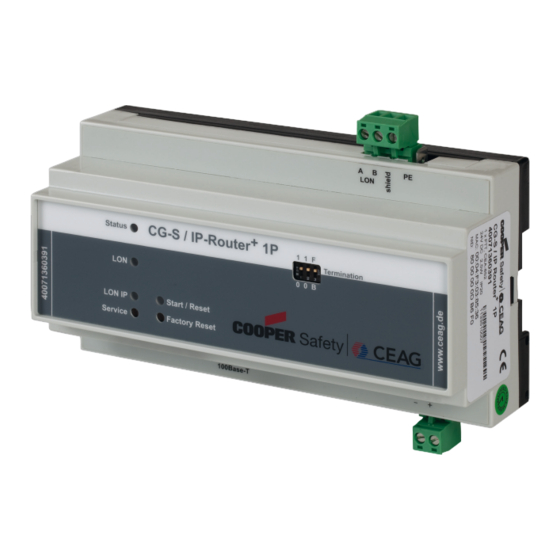
Seite 7: Leds, Taster Und Dil-Schalter
Bei vielen CG-S/IP-Routern+ 1P im Netzwerk, empfiehlt sich dringend die Betriebsart „Multicast“ um die Buslast deutlich zu reduzieren, und Kommunikationsstörungen zu vermeiden. Konfiguration und Diagnose des Gerätes erfolgen über ein eingebautes Web-Interface. LEDs auf der Gehäuseober- seite geben Aufschluss über den Status der Router Schnittstellen. Mit Hilfe von Tastern lassen sich verschiedene Service-Funktionen auslösen, während über DIL-Schalter ein Busabschluss für das angeschlossene LON/FT Seg- ment geschaltet werden kann. - Seite 8 LEDs Auf der Gehäuseoberseite sowie an der seitlichen RJ45-Buchse gibt es folgende LEDs: • Status: Nach dem Einschalten leuchtet diese LED zunächst rot. Sobald der Router betriebsbereit ist, wech- selt diese auf grün. Hat das Gerät einen Fehler erkannt, leuchtet die LED dauerhaft rot. Eine Überlastsituation auf einem der beiden Kanäle wird durch eine permanent rote Status-LED sowie das Einschalten der jeweiligen Kanal-LED für eine Sekunde angezeigt.
-
Seite 9: Wichtige Hinweise
Um Zugriff auf die Einstellungsmöglichkeiten des Routers über das Web-Interface zu erhalten, ist bei Auslieferung ein Benutzer mit dem Namen „admin“ und dem Passwort “ceag“ vorhanden. Ändern Sie das Passwort bitte umge- hend nach der erstmaligen Inbetriebnahme. 3. Das Gerät einrichten 3.1 Kabel anschließen... -
Seite 10: Software Installieren
3.2 Software installieren Auf dem mitgelieferten Datenträger der CGVision finden Sie die Dokumentation des CG-S / IP-Router+ 1P und das Programm „ DeviceFinder“ zum Suchen des Gerätes über Ethernet. Alle weiteren Einstellungen lassen sich über das eingebaute Web-Interface des Routers vornehmen. 3.3 Verbindung zum Web-Interface herstellen Über das Web-Interface des CG-S / IP-Router+ 1P lassen sich Statusin-formationen abrufen und weitere Einstel- lungen vornehmen. - Seite 11 Vom DeviceFinder wird die MAC-Adresse (HW-Address), die IP-Adresse und die Subnet Maske angezeigt. Die Sortierung erfolgt nach der MAC-Adresse. Die Spalte DHCP gibt an, ob die IP-Adresse über einen DHCP Server zugewiesen wurde. Achten Sie darauf, dass die Default IP-Adresse des Routers in Ihrem Netzwerk nicht schon an ein anderes Gerät vergeben wurde, sonst könnte die Kommunikation wegen Kollisionen gestört sein.
- Seite 12 2. Geben Sie zunächst den Befehl ipconfig ein, um die aktuelle IP-Adresse Ihres Rechners abzurufen, 3. Geben Sie den Befehl route add 192.168.1.250 mask 255.255.255.255 xxx.xxx.xxx.xxx ein (wobei xxx.xxx.xxx. xxx die ak-tuellen IP-Adresse Ihres PCs ist) 4 . Geben Sie dann in der Adresszeile Ihres Webbrowsers die IP-Adresse 192.168.1.250 ein, um das Web-Interface zur Konfiguration des Routers aufzurufen.
-
Seite 13: Ip-Adresse Festlegen
ändern. Um Zugriff auf die Einstellungsmöglichkeiten des Routers über das Web-Interface zu erhalten, ist bei Auslieferung ein Benutzer mit dem Namen „admin“ und dem Passwort “ceag“ eingerichtet. Ändern Sie das Passwort bitte umgehend nach der erstmaligen Inbetriebnahme. In den Feldern IP Address, Subnet Mask, Gateway, DNS 5 und TTL 6 können Sie nun die gewünschten Werte eintra- gen. -
Seite 14: Zeiteinstellungen Anpassen
Die Verwendung einer Software MAC Address, die, sofern angegeben, die Hardware MAC Address des Gerätes ersetzt muss mit Überlegung erfolgen. Bei Auftreten von Geräten mit gleicher MAC Adresse kann es zu ernsthaften Störungen im Netzwerk kommen. 3.5 Zeiteinstellungen anpassen Die CEA-852 Norm empfiehlt für ein LON/IP Netzwerk die Synchronisation der Router, um die Erkennung von veral- teten Nachrichten zu erlauben. -
Seite 15: Kennwort Ändern, Benutzer Verwalten
Ist der Configuration Server als NTP Server aktiviert, so werden die Einstellungen hier überschrieben. Die in Abbildung gezeigten Einstellungen bedeuten: • Der Router ist NTP Server für andere Geräte • Es gilt die eingetragene Zeit • Die unter NTP Servers genannten Server werden nicht benutzt, da bei NTP Client kein Häkchen ist. Klicke Sie auf Save, um die Einstellungen zu speichern. 3.6 Kennwort ändern, Benutzer verwalten Ändern Sie beim ersten Einloggen auch das Kennwort des Standardbenutzers “admin”. -
Seite 16: Configuration Server
4. Configuration Server Der CG-S / IP-Router+ 1P verfügt über einen integrierten Configuration Server, der über das Web interface aktiviert werden kann. Dieser verwaltet über alle anderen CG-S / IP Router im Netzwerk und dem CG-S / IP-Intercace (CGVi- sion PC). 4.1 Configuration Server einrichten Die Aktivierung des Configuration Servers auf dem CG-S / IP-Router+ 1P erfolgt über dessen Web-Interface. -
Seite 17: Router Über Configuration Server Verwalten
Alle Teilnehmer eines LON/IP-Kanals müssen dieselbe Multicast-Adresse und dieselbe Port-Nummer nutzen. Channel Timeout: Mit dem Channel Timeout werden verspätete IP Pakete erkannt. Wird hier ein Wert angegeben, dann müssen alle Devices im Netz genau die gleiche Uhrzeit haben. Der Wert wird in Millisekunden zwischen 1 und 1500 angegeben. - Seite 18 Abbildung: CEA-852 Channel List In der Karteikarte IMFORMATION ist diese Liste ohne die Bearbeitungsfunktionen einsehbar. Die Liste ist durch Klicken auf die Spaltenüberschriften sortierbar. Der Status der Geräte wird durch folgende Farben angezeigt: Grün: Registrierter Client Gelb: In Bearbeitung, wird evtl. gerade registriert Rot: registriert aber Keine Antwort Grau:...
-
Seite 19: Tipps Zu Configuration Server Einstellungen
Die Befehlsschaltflächen unter der Liste haben folgende Bedeutung, die sich jeweils auf die ausgewählten Geräte bezieht: Ein weiterer Router kann manuell in die Liste eingetragen werden. Edit IP-Adresse, Port. Name und Gruppenzugehörigkeit können bearbeitet werden. Delete Das Gerät wird aus der Liste gelöscht, d.h. es erhält keine Information über andere Geräte und nimmt dann an der Kommunikation nicht mehr teil. -
Seite 20: Router-Funktionalität Nutzen
5. Router-Funktionalität nutzen 5.1 LON/IP-Schnittstelle konfigurieren Die Konfiguration des CEA-852-Interfaces erfolgt über das Web-Interface des CG-S / IP-Router+ 1P. Geben Sie die IP-Adresse des Routers in die Adresszeile eines Webbrowsers auf einem PC ein, der mit diesem verbundenen ist. Gehen Sie auf die Karteikarte SETTINGS und wählen CEA-852 Device unter CATEGORIES. Abbildung: CEA-852 Einstellungen... - Seite 21 Wird der CG-S / IP-Router+ 1P zugleich als Configuration Server eingesetzt, so stehen bestimmte Device Einstellungen (z. B. NTP Server, Unicast, Multicast Adressen) nicht zur Verfügung, da sie von den entsprechenden Server Einstellungen überschrieben werden. Device Name Vergeben Sie zunächst eine eindeutige Bezeichnung für das Gerät unter Device Name. Als Default wird hier die Ba- sic Node-ID verwendet .
- Seite 22 Abbildung: Statistische Daten zur LON/IP Schnittstelle Aggregation Timeout In der Regel sind LonWorks Pakete wesentlich kürzer als die maximal mögliche Länge eines Ethernet-Paketes. Daher sind LON/IP Geräte in der Lage LonWorks (CG-S Bus) Pakete für einen kurzen Zeitraum zu sammeln und dann in einem einzigen Ethernet-Paket zu verschicken.
-
Seite 23: Serviceprozeduren Durchführen
Mit Hilfe von Channel Routing wird also auch wieder die Netzwerklast reduziert. Insbesondere erhalten die LON/IP Geräte nur die Ethernet-Pakete die auch sinnvoll sind. Daher ist das Channel Routing im Normalfall eingeschaltet. Zur Diagnose kann es hier über die Checkbox ausge- schaltet werden. -
Seite 24: Firmware Aktualisieren
Abbildung: Konfiguration abspeichern/hochladen 6.3 Firmware aktualisieren CEAG stellt Aktualisierungen zur Firmware des Routers in Form spezieller .GUF-Dateien zur Verfügung, die Sie über die Webseite www.ceag.de beziehen können. Um eine neue Firmware auf das Gerät aufzuspielen, gehen Sie im Web-Interface auf die Karteikarte SETTINGS und dann links unter CATEGORIES auf Firmware. -
Seite 25: Probleme Lösen
2. Leuchtet die Status LED grün? Sollte die Status LED spätestens drei Minuten nach dem Einschalten nicht grün leuchten, so nehmen Sie bitte Kontakt mit dem Service der Firma Ceag auf. 3. Blinkt die Status LED rot oder rot/grün ? In diesem Fall hat der Router Probleme mit der IP-Adresse. -
Seite 26: Die Lon Led Flackert Nicht
Lösungsvorschläge Dieses Problem ist leider nicht zu lösen. Verwenden Sie einen anderen DSL Router. 7.3 Die LON LED flackert nicht Symptome Die LON LED bleibt dunkel. Mögliche Ursachen • Fehlerhafter Anschluss beim LON/FT Kanal • Falsche Terminierung • Fehlerhafte Konfiguration der LON/IP Schnittstelle Lösungsvorschläge 1. -
Seite 27: Kommunikationsprobleme Auf Dem Lon/Ip Kanal
Abbildung: Statistik der LON/IP Schnittstelle Für die Kommunikation mit dem Configuration Server ist wichtig, dass Sie in der Spalte Received Werte ehen. Die Werte für UDP Packets und Multicast Packets geben Werte für den CEA-852 Datenverkehr an. Prüfen Sie, ob die Multicast Adresse auf allen Geräten identisch konfiguriert ist. - Seite 28 Ebenfalls können Sie im Web-Interface den Status der Kommunikation mit dem Configuration Server kontrollieren. Sie sehen dies auf der Karteikarte INFORMATION unter CEA-852 Device. Über die Karteikarte STATISTICS des Web-Interface können Sie einen Kommunikationstest mit den anderen Geräte am LON/IP Kanal durchführen. Öffnen Sie dazu die Kategorie CEA-852 Devices. Sie sehen im rechten Bereich den Link Get Device Channel List und betätigen diesen (s.