Kessel Aqualift F Anleitung Für Einbau, Bedienung Und Wartung
Kessel-pumpstation
Vorschau ausblenden
Andere Handbücher für Aqualift F:
- Anleitung für einbau, bedienung und wartung (228 Seiten) ,
- Anleitung für einbau, betrieb und wartung (180 Seiten) ,
- Einbau- und bedienungsanleitung (148 Seiten)
Inhaltsverzeichnis
Verfügbare Sprachen
Verfügbare Sprachen
ANLEITUNG FÜR EINBAU, BEDIENUNG UND WARTUNG
KESSEL-Pumpstation
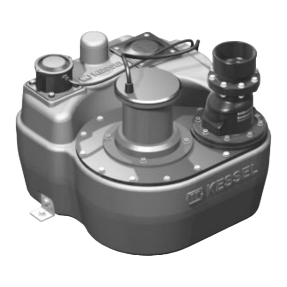
Aqualift F /Aqualift F Duo Standard
für fäkalienhaltiges und fäkalienfreies
Abwasser zum Einbau ins Erdreich
qualift F
Installation
der Anlage wurde durchgeführt von Ihrem Fachbetrieb:
Name/Unterschrift
Stand 2012/07
Aqualift F Duo
Inbetriebnahme
Datum
Einweisung
Ort
Bedienungsanleitung
Seite 1-40
Installation Manual
Page 41-80
Istruzioni per l'installazion
Pagina 81-120
Produktvorteile
Einfache und schnelle Mon-
tage durch geringes Gewicht
Hohe Sicherheit durch
Wasserdichtheit und
Beständigkeit gegen
aggressive Medien
Anbohrflächen für weitere
Anschlüsse frei wählbar
Aufsatzstück teleskopisch
höhenverstellbar und neigbar
Stempel Fachbetrieb
Sach-Nr. 328-200
Kapitel
Inhaltsverzeichnis
Fehlerbehebung

Verwandte Anleitungen für Kessel Aqualift F


Inhaltszusammenfassung für Kessel Aqualift F
- Seite 1 ANLEITUNG FÜR EINBAU, BEDIENUNG UND WARTUNG KESSEL-Pumpstation Bedienungsanleitung Seite 1-40 Installation Manual Aqualift F /Aqualift F Duo Standard Page 41-80 Istruzioni per l’installazion für fäkalienhaltiges und fäkalienfreies Pagina 81-120 Abwasser zum Einbau ins Erdreich qualift F Produktvorteile Aqualift F Duo...
- Seite 2 Sie bitte die Anweisungen in Kapitel „Gewährleistungen“ dieser Anleitung. Bevor Sie die KESSEL-Pumpstation Aqualift F installieren und in Betrieb nehmen, ist es - in Ihrem eigenen Interesse - un- verzichtbar, daß Sie diese Einbau-, Bedienungs- und Wartungsanleitung sorgfältig lesen und befolgen.
-
Seite 3: Inhaltsverzeichnis
Inhaltsverzeichnis ..................Seite 1. Sicherheitshinweise Einsatzbereich ............Seite Anlagenbeschreibung ..........Seite 2. Allgemeines Pumpen...............Seite Schaltpunkte der Niveauschalter ........Seite 3. Technische Daten Elektrisches Schaltgerät..........Seite Montage Schachtsystem..........Seite 10 Anschluß der Rohrleitungen........Seite 13 4. Einbau und Montage Einsetzen der Fäkalienpumpe(n) ........Seite 14 Einstellung der Schwimmerschalter ......Seite 14 Allgemeine Hinweise...........Seite 15 Montage des Schaltgeräts ..........Seite 15 5. -
Seite 4: Sicherheitshinweise
1. Sicherheitshinweise Allgemeine Sicherheitsvorkehrungen Bei Installation, Betrieb, Wartung oder Reparatur der Anlage sind die Unfallverhütungsvorschriften, die in Frage kommenden DIN- und VDE-Normen und Richtlinien sowie die Vorschriften der örtlichen Ener gie- und Versorgungsunternehmen zu beachten. Weiter sind auch die Sicherheitsvorschriften für den Explosionsschutz in abwassertechnischen Anlagen zu beachten. - Seite 5 IEC 38 oder andere Netze bzw. Versorgungseinrichtungen mit Nennspannungstoleranzen von max. ± 10 % angeschlossen werden. Der Motor ist mit einer Überlastschutzeinrichtung abzusichern. Diese sind im KESSEL-Schaltgerät rea- lisiert durch: - Strombegrenzung (Motorschutzschalter gemäß EN 60 974-2). Eine Abschaltung des Motors im Betrieb beim 1,15-fachen Bemessungsstrom innerhalb von 15 Minuten.
-
Seite 6: Einsatzbereich
Größe im Aufsatzstück oder auf einer separaten Pa- lette angeliefert. Sie sind erst nach der kompletten Montage Die KESSEL-Pumpstation Aqualift F ist zum Einbau ins Erd- in den Schacht einzusetzen. reich außerhalb des Gebäudes vorgesehen. Die Abwasser- Damit die gefährliche explosionsfähige Atmopshäre entwei-... -
Seite 7: Technische Daten
3. Technische Daten 3.1 Pumpen in explosionsgeschützter Ausführung nach ATEX Aufnahmeleistung (P1) 1,75 kW 2,6 kW TPF 1,3 TPF 1,9 Nennleistung (P2) 1,3 kW 1,9 kW Betriebsspannung 400 V DS Nennfrequenz 50 Hz Nennstrom 3,56 A 4,5 A Absicherung 3 x 16 A träge Schutzart IP 68 Anschlußleitung... -
Seite 8: Schaltpunkte Der Niveauschalter (Schwimmerschalter)
3. Technische Daten 3.2 Schaltpunkte der Niveauschalter (Schwimmerschalter) Schachtsystem 800 Schachtsystem 1000 Volumendiff., ca. [I] Höhendifferenz [cm] Volumendiff., ca. [I] Höhendifferenz [cm] Einzelanlage Aus - Ein Ein - Alarm Doppelanlage Aus - Ein1 Ein1 - Ein2 Ein2 - Alarm Die Alarmniveaus liegen jeweils etwa auf Höhe der Unterkante der Zulaufrohrsohle. Die Anforderungen der Normen EN 50014:1997 + A1-A2, EN 3.3 Elektrisches Schaltgerät mit Zenerbarrieren 50020:2002 werden erfüllt. - Seite 9 3. Technische Daten Typ Einzelanlage Instandhaltung/Wartung Niveaustromkreis in Zündschutzart Eigensicherheit • Durch öffnen des Deckels reduziert sich die angegebene EEx ia IIC Schutzart (Dichtigkeit). Stellen Sie vorher fest, ob eine Gefährdung (Klemmen AUS, EIN, ALARM) durch hohe Feuchtigkeit, Spritzwasser oder sonstige Verunreini- gungen gegeben ist.
-
Seite 10: Elektrisches Schaltgerät
4. Einbau und Montage Im Lieferumfang sind folgende Teile enthalten (siehe Ab- schnitt 2.2): Einbau Bodenteil - KESSEL-Schachtsystem (in Bauteilen zur Vor-Ort- Montage) - Fäkalienpumpe(n) - elektrisches Schaltgerät Das elektrische Schaltgerät ist frostfrei und trocken auf- WICHTIG: zubewahren. Wenn die Anlage beim Einbau noch nicht elektrisch angeschlossen wird, ist das Schaltgerät dem-... - Seite 11 Montage des teleskopischen Aufsatzstückes • Dichtung mit Hammer einschlagen • Lippen - dichtung einfetten, Aufsatzstück einsetzen und mit Klemmring fixieren. • Fein - justierung kann mit Stell - schrauben vorgenom- Die Steighilfen sind nur beim KESSEL-Schachtsystem 1000 men werden. im Lieferumfang enthalten...
- Seite 12 2,0 x 2,0 m bauseits zu unterfüttern (siehe Abbil- dung rechts beim Abschnitt „Einbau Bodenteil“). Mögliche Einbautiefen KESSEL-Pumpstation Aqualift F im Schachtsystem 1000 Einbautiefen von 1,63 bis 5,13 Meter KESSEL-Pumpstation Aqualift F im Schachtsystem 800 Einbautiefe von 1,46 bis 1,96 Meter...
-
Seite 13: Anschluß Der Rohrleitungen
Entleeren bzw. Füllen der Anlage zu- bzw. abströ- 4.2 Anschluß der Rohrleitungen Alle Rohrleitungen sind grundsätzlich so zu verlegen, daß mende Luft her. Da das KESSEL-Schachtsystem mit Fakä- die se von selbst leerlaufen können. Alle Leitungsanschlüs- lienhebeanlage in der Regel nahe dem zugehörigen Gebäu - se müssen flexibel und im Haus schalldämmend ausgeführt... -
Seite 14: Einsetzen Der Fäkalienpumpe(N)
4. Einbau und Montage 4.3 Einsetzen der Fäkalienpumpe(n) 4.4 Einstellung der Schwimmerschalter Die Schwimmerschalter sind werksseitig montiert (siehe Ab- Eine Pumpe TPF 1,3 kW und 1,9 kW wiegt 39 kg. Die Teile schnitt 3.2) und voreingestellt. Eine Veränderung der Ein- ACHTUNG: dürfen nur in geeigneter Weise mit entsprechender Vor- stellung kann zu Störungen führen. -
Seite 15: Allgemeine Hinweise
5. Elektroanschluss Be reich installiert werden. An keinem der Niveaueingänge Nur Elektrofachkräfte dürfen die nachfolgend beschriebe - „Aus“, „Ein“ bzw. „Ein 1“ / „Ein 2“ bei Doppelanlagen, „Alarm“ nen Arbeiten an den elektrischen Einrichtungen durch füh - darf eine externe Spannung zugeführt werden. ren. -
Seite 16: Befestigung Der Elektrischen Anschlussleitung
5. Elektroanschluss Wicklungstemperaturfühler = Bimetallschalter (Öffner) in Motorwicklung Max. Betriebsspannung des Schalters 250 V, max. Schal- terstrom 2 A bei cos phi = 1 Aderkennzeichnung 20, 21, 22 Die elektrische Anschlussleitung sollte nach dem Einbau des 5.5.2 Befestigung der elektrischen Anschlussleitung Aggregates möglichst gestreckt nach oben geführt werden, damit sie nicht vom Fördersog erfasst wird. - Seite 17 5. Elektroanschluss Die einzelnen Anschlussarbeiten sind in der nachfolgenden Tabelle sowie in den Anschlussplänen im Kapitel 9 auf geführt. Zu beachten sind dabei auch die jeweiligen Erläuterungen in Kapitel 8, Elektrisches Schaltgerät (Lage der Bedienelemen- te, Innenansicht des Schaltgerätes). EINZELANLAGE - Sicherheitshinweise beachten ! •...
- Seite 18 5. Elektroanschluss EINZELANLAGE - Sicherheitshinweise beachten ! Auszuführende Arbeit Schaltgerät ab Baujahr 01/10 Schaltgerät bis Baujahr 12/09 • Die „Störung“- und „Warnung“-Meldung er- • Die „Störung“- und „Alarm“-Meldung er- folgt über je ein Relais (Wechsler) ohne folgt über je ein Relais (Wechsler) ohne Ausgänge „Störung“...
- Seite 19 5. Elektroanschluss DOPPELANLAGE - Sicherheitshinweise beachten ! Auszuführende Arbeit Schaltgerät ab Baujahr 01/10 Schaltgerät bis Baujahr 12/09 Der Akku (1 x 9V-Block) ist in die • Beide Batterien (2 x 9V-Block) sind auf Akkuhalterung einzustecken der Platine anzuschliessen. Batterieanschluss • Netzzuleitung L1 / L2 / L3 / N / PE am •...
- Seite 20 5. Elektroanschluss DOPPELANLAGE - Sicherheitshinweise beachten ! Auszuführende Arbeit Schaltgerät ab Baujahr 01/10 Schaltgerät bis Baujahr 12/09 Die Kabelenden der Schwimmerschalter • Die Kabelenden der Schwimmerschalter sind an die entsprechenden Klemmen auf sind an die entsprechend gekennzeichne- Niveauerfassung / der HAZARD-Seite der Zenerbarriere an- ten Klemmen anzuschließen.
-
Seite 21: Kontrollen
5. Elektroanschluss 5. 6 Kontrollen 5.7 Abschluß der Elektroarbeiten Nach dem vollständigen Elektroanschluss ist der Deckel wie- der ordnungsgemäß zu schliessen. Um Geruchsbelästigun- Die Motorschutzschalter müssen auf die Werte für gen im Gebäude zu vermeiden, sollte das Kabelleerrohr - werden, wie sie in Abschnitt 3 angegeben sind. den Nennstrom der zugehörigen Pumpen eingestellt nach Abschluß... -
Seite 22: Allgemeine Hinweise
6. Inbetriebnahme 6.1 Allgemeine Hinweise Der Betrieb der Pumpe im ausgetauchten Zustand Für die Inbetriebnahme von Hebeanlagen ist die DIN 1986, führt zu erhöhtem Verschleiß und ist zu vermeiden! Teil 31, zu beachten. Pumpen mit S-Laufrad werden bevorzugt für schlammhalti- 6.1.1 Ansaugen von Schwebstoffen ges Wasser mit Schwebstoffen eingesetzt. -
Seite 23: Funktionsbeschreibung
6. Inbetriebnahme rungszeit) eingeschaltet. Dieser Parallelbetrieb der Pumpen dauert an, bis das „Aus“-Niveau unterschritten und die Nach- 6.3 Funktionsbeschreibung laufzeit abgelaufen ist. 6.3.1 Betriebsart „Auto“ Bei Überschreiten der maximalen Grenzlaufzeit erfolgt die Störmeldung und die Abschaltung der jeweiligen Pumpe wie Einzelanlage Die Grundfunktion erfolgt, wenn die Netz-LED (grün) leuch- bei der Einzelanlage. -
Seite 24: Funktionsbeschreibung
Störung (ALARM-LED) angezeigt wird. Mit steigendem (Schmutzwasser-) Niveau im Behälter wird über die Schwimmerschalter das EIN-Niveau erkannt und die Pumpe eingeschaltet wird. Durch den Betrieb der 6.6 Bedienung des Schaltgerätes Aqualift F Mono 400V Kurzbedienungsanleitung: Œ Netzverbindung herstellen grüne Netzanzeige... -
Seite 25: Pumpe
7. Inspektion und Wartung Für alle Arbeiten an der Pumpe empfiehlt es sich (nach er- Inspektion Die Anlage ist monatlich vom Betreiber durch Beobachtung folgter Trennung vom Netz), die Pumpe aus dem Schacht zu eines Schaltspiels auf Betriebsfähigkeit und Dichtheit zu heben, einer Grobereinigung (z.B. -
Seite 26: Elektrisches Schaltgerät
überprüft und gegebenenfalls gewechselt werden. Beim Wechseln ist auf umweltge- rechte Entsorgung zu achten. Ersatz darf nur durch glei- Eine Demontage der Pumpe darf nur von einem zertifizier- 7.3 Demontage Pumpe chen Typ (siehe Kapitel 9) erfolgen. ten KESSEL-Kundendienst durchgeführt werden. -
Seite 27: Allgemeine Störungen
• Fremdkörper in der Druckarmatur oder in der Druckleitung entfernen • Pumpen sind abgenutzt, Austausch vorneh- men lassen • Falsche Auslegung der Hebeanlage, Klärung über KESSEL-Kundendienst Anlüftevorrichtung nicht in Betriebsstellung Anlüftevorrichtung in Betriebsstellung bringen Falsches Drehfeld an Zuleitung Drehrichtung prüfen, bei falscher Drehrichtung... -
Seite 28: Irreguläre Niveauzustände
Anlage auf Schaltstörungen prüfen (vor allem Beißender Geruch Motorschutzschalter) Zu häufiges Ein- und Ausschalten der Anlage durch zu hohe Zulaufmengen, Klärung mit KESSEL-Kundendienst Anlage auf Schaltstörungen prüfen. Schütze zu heiß durch Schalt- störungen Ursachen feststellen und beseitigen Zulaufmenge zu hoch durch Fremdwasser o.ä. - Seite 29 8. Störungen und Abhilfemaßnahmen = leuchten = aus ● = langsames Blinken ❍ = schnelles Blinken 8.2 Störungsmeldungen / Abhilfemaßnahmen (ab Baujahr 01/10) Batteriefehler - Alarm und Alarmtaste quittieren - prüfen, ob Batterien angeschlossen sind - entladene Batterien tauschen - nach quittieren des Signaltons Alarmtaste erneut drücken -->...
- Seite 30 8. Störungen und Abhilfemaßnahmen - Drehfeldfehler: Drehfeld / Phasenfehler falsches Drehfeld bei Netzanschluss Schaltgerät --> 2 Phasen tauschen - Phasenfehler: Phase L1 oder L2, L3 nicht vorhanden --> Anschluss am Shaltgerät, Netzkabel, Sicherungen prüfen, Duo Pumpe 1/2 Fehlerstromschutzschalter prüfen --> Bei Ausfall von L1 kann Drehfeldrichtung nicht erkannt werden. -->...
-
Seite 31: Störungen / Interne Überwachung
8. Störungen und Abhilfemaßnahmen Niveaufehler - Niveaufehler: Ein Schwimmer zeigt Niveau an, ohne dass ein darunterliegender Schwimmer ange- sprochen hat (falsche Reihenfoge Schwimmer) --> Schwimmerkabel der darunterliegenden Schwimmer prüfen --> Schwimmer im Behälter auf Funktion prüfen (anheben) --> Die Pumpe(n) wird eingeschaltet. Duo Pumpe 1/2 Das Schaltgerät arbeitet mit den erkannten Niveaus. -
Seite 32: Motortemperatur
8. Störungen und Abhilfemaßnahmen - Grenzlaufzahlfehler - Grenzlaufzeitfehler bzw. bei Doppelanlagen mit 8.3.2 Motorschutzschalter Hat ein Motorschutzschalter aufgrund von Handbetätigung, - Phase/Drehfeld Kurzschluß oder Überlast ausgelöst, so erfolgt eine Stör- - Motorschutzschalter meldung über Display und LED, sowie das „Störung“-Relais. - Motortemperatur Außerdem wird der Schütz für den Motorausgang von der - Laufzeit/Niveau... -
Seite 33: Anschlussplan Schaltgerät Für Einzelanlage
9. Schaltgerät Schaltgerät • Die Bedienelemente sind zugänglich. Das Öffnen des Ge - Elektrofachkraft hinzu zu ziehen. häu sedeckels zum Zwecke der Bedienung ist zulässig, je- • Der am Motorschutzschalter eingestellte Strom muß dem doch nur für Servicearbeiten sinnvoll. an geschlossenen Motor entsprechen und darf nicht durch •... -
Seite 34: Ersatzteile
10. Ersatzteile 10 Ersatzteilhaltung Für Ex-geschützte Aggregate dürfen nur gekenn- zeichnete Original-Ersatzteile des Herstellers ver- wendet werden. Bitte geben Sie bei Ersatzteilbestellung immer fol- gende Daten an. Diese Angaben sind dem Typen- Pumpentyp: schild zu entnehmen: z.B. TPF 1,3 kW 10.1 Ersatzteil-Liste Ersatzteil Teile-Nr. -
Seite 35: Gewährleistung
11. Gewährleistung 1. Ist eine Lieferung oder Leistung mangelhaft, so hat KESSEL Über die gesetzliche Regelung hinaus erhöht die KESSEL AG die nach Ihrer Wahl den Mangel durch Nachbesserung zu beseitigen Gewährleistungsfrist für Leichtflüssigkeitsabscheider, Fettab- oder eine mangelfreie Sache zu liefern. Schlägt die Nachbesse- scheider, Schächte, Kleinkläranlagen und Regenwasserzister-... - Seite 36 NOTIZEN...
-
Seite 37: Übergabeprotokoll
Übergabeprotokoll Typenbezeichnung * KESSEL-Bestellnummer * Fertigungsdatum * (* gemäß Typenschild/Rechnung) Objektbezeichung / Anlagenbetreiber Adresse Telefon / Telefax Planer Adresse Telefon / Telefax Ausführende Baufirma Adresse Telefon / Telefax Ausführende Sanitärfirma Adresse Telefon / Telefax Ausführende Elektrofirma Adresse Telefon / Telefax... - Seite 39 Übergabeprotokoll...
- Seite 40 Rückstauverschlüsse Kleinkläranlagen Hebeanlagen Schächte Abläufe / Duschrinnen Regenwassernutzung Abscheider -Fettabscheider -Öl-/ Benzin-/ Koaleszenzabscheider -Stärkeabscheider -Sinkstoffabscheider...