Kessel Aqualift F Duo Anleitung Für Einbau, Bedienung Und Wartung
Vorschau ausblenden
Andere Handbücher für Aqualift F Duo:
- Anleitung für einbau, bedienung und wartung (216 Seiten) ,
- Anleitung für einbau, betrieb und wartung (180 Seiten) ,
- Einbau- und bedienungsanleitung (148 Seiten)
Inhaltsverzeichnis
Verfügbare Sprachen
Verfügbare Sprachen
ANLEITUNG FÜR EINBAU, BEDIENUNG UND WARTUNG
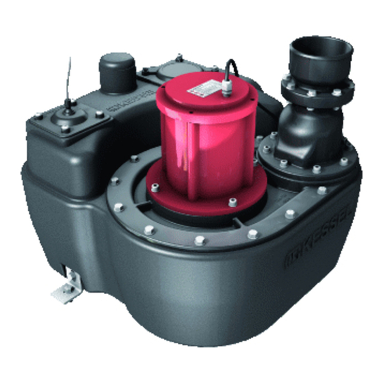
KESSEL-Hebeanlage Aqualift F Mono/Duo
für fäkalienhaltiges und fäkalienfreies Abwasser
zur freien Aufstellung in frostgeschützten Räumen
o Installation
der Anlage wurde durchgeführt von ihrem Fachbetrieb:
Name /Unterschrift
Stand 2013/09
o Inbetriebnahme
Datum
o Einweisung
Ort
Stempel Fachbetrieb
D
Seite 1
GB
Page 39
F
Page 77
I
Page 115
NL
Page 153
PL
Page 191
Produktvorteile
Sicherheit durch Schalt-
gerät mit SDS-Funktion
(Selbst-Diagnose-System)
Drucksensor zur
sicheren Aufnahme von
Füllständen
Anbohrflächen für weitere
Anschlüsse bis DN 200
Bodenteil mit Gefälle zum
Ansaugpunkt der Pumpe
Alle Behälter passen
durch 800er Normtüren
Armaturen aus Kunststoff
Befestigungsmaterial zur
Auftriebssicherung
inklusive
Sach-Nr. 206-818DE
Kapitel
Inhaltsverzeichnis
Fehlerbehebung

Verwandte Anleitungen für Kessel Aqualift F Duo


Inhaltszusammenfassung für Kessel Aqualift F Duo
- Seite 1 ANLEITUNG FÜR EINBAU, BEDIENUNG UND WARTUNG KESSEL-Hebeanlage Aqualift F Mono/Duo für fäkalienhaltiges und fäkalienfreies Abwasser zur freien Aufstellung in frostgeschützten Räumen Seite 1 Page 39 Page 77 Page 115 Page 153 Page 191 Produktvorteile Sicherheit durch Schalt- gerät mit SDS-Funktion...
-
Seite 2: Inhaltsverzeichnis
INHALTSVERZEICHNIS Inhaltsverzeichnis Inhaltsverzeichnis Allgemeines Einleitung und Begrüßung Produktbeschreibung, allgemein 2.2.1 Ausführungen 2.2.2 Typenschild Allgemeine Hinweise zu dieser Betriebs- und Wartungsanleitung Lieferumfang 2.4.1 Baugrupppen und Funktionselemente Sicherheit Bestimmungsgemäße Verwendung Personalauswahl und -qualifikation Organisatorische Sicherheitsmaßnahmen 3.3.1 Gefahr durch elektrischen Strom und Kabel 3.3.2 Gefahr durch heiße Oberflächen 3.3.3 Gefahr durch Lärm 3.3.4 Gefahr für die Gesundheit... - Seite 3 8.2.7 Schaltplan Einzelanlage (bis Baujahr 12/09) 8.2.8 Schaltplan Einzelanlage (bis Baujahr 12/09) 8.2.9 Schaltgerät für Doppelanlage (bis Baujahr 12/09) 8.2.10 Schaltplan Doppelanlage (bis Baujahr 12/09) 8.2.11 Schaltplan Doppelanlage (bis Baujahr 12/09) Ersatzteile Aqualift F Mono Aqualift F Duo DOP /Leistungserklärung V 1.0 3/228...
-
Seite 4: Allgemeines
2.2. Produktbeschreibung, allgemein Die KESSEL Hebeanlage Aqualift F (im folgenden Anlage benannt) ist für das Abpumpen von fäkalienfreiem und fäkalienhaltigem Abwasser vorgesehen. Der Abwasserbehälter nimmt die Pumpe(n) und den/die Niveausensor(en) auf. Die Baugruppen sind so konzipiert, dass sie unmittelbar an ein KESSEL-Schaltgerät angeschlossen werden können. -
Seite 5: Typenschild
7 QR-Code 10 Revisionsstand der Hardware 28 CE-Zeichen Aqualift F Mono/Duo XXXXX XXXV XXHz X,XA X,XkW XXm/h S3 XX% ED IP XX (XmWS/2h) Ser. Nr. XXXXXXXXX RevStd.: X.X MM/JJ DIN-EN 1 Aqualift F Mono/Duo XXXXX www.kessel.de/info XXXXXXXXXX V 1.0 5/228... -
Seite 6: Allgemeine Hinweise Zu Dieser Betriebs- Und Wartungsanleitung
ALLGEMEINES 2.3. Allgemeine Hinweise zu dieser Betriebs- und Wartungsanleitung Verwendete Symbole und Legenden <1> Hinweis im Text auf eine Legendennummer in einer Abbildung Bezug auf eine Abbildung Arbeitsschritt Aufzählung Kursiv Kursive Schriftdarstellung: Bezug zu einem Abschnitt / Punkt im Steuerungs-Menü VORSICHT: Warnt vor einer Gefährdung von Personen und Material. -
Seite 7: Baugrupppen Und Funktionselemente
ALLGEMEINES 2.4.1 Baugrupppen und Funktionselemente Abwasserpumpe(n) Rückflussverhinderer Absperrschieber * Entlüftungsanschluss DN70 Zulaufanschluss DN100/150 Reinigungsdeckel Anbohrflächen Zulauf Anschluss Handmembranpumpe DN40 Niveaugeber ** Klappe Rückflussverhinderer * Optional ** Tauchrohr (wenn nicht anders konfiguriert) 17 * Die Abbildung kann sich in Form und Ausprägung von den Ausstattungsmerkmalen Ihrer Anlage unterscheiden. -
Seite 8: Sicherheit
SICHERHEIT Sicherheit 3.1. Bestimmungsgemäße Verwendung Die Anlage ist ausschließlich für das Abpumpen von fäkalienfreiem und fäkalienhaltigem Abwasser zu verwenden. Ein Einsatz der Anlage in explosionsgefährdeter Umgebung ist unzulässig. Alle nicht durch eine ausdrückliche und schriftliche Freigabe des Herstellers erfolgten Betrieben oder Personen können zum Verlust der Gewährleistung führen. -
Seite 9: Gefahr Durch Elektrischen Strom Und Kabel
SICHERHEIT Gefahren, die vom Produkt ausgehen 3.3.1 Gefahr durch elektrischen Strom und Kabel Alle spannungsführenden Bauteile sind gegen unbeabsichtigte Berührung geschützt. Vor einem Öffnen von Ge- häuseabdeckungen, Steckern und Kabeln sind diese spannungsfrei zu machen. Arbeiten an elektrischen Bautei- len dürfen nur von Fachpersonal (Siehe 2.2) durchgeführt werden. 3.3.2 Gefahr durch heiße Oberflächen Während dem Betrieb erhitzen sich Antriebsmotore von Pumpen. -
Seite 10: Montage
MONTAGE Montage 4.1. Montagevoraussetzungen Die Anlage muss auf ausreichend tragfähigen (Gewicht in befülltem Zustand berücksichtigen) und ebenen Un- tergrund aufgestellt werden. Der Untergrund muss zur Aufnahme der Bodenbefestigungen (pro Schraube, 0,9 kN) geeignet sein, die ein Auf- schwimmen der Anlage verhindern sollen. Anschlussleitungen (Zu- und Ablauf sowie Entlüftung) müssen selbsttragend befestigt werden, sie dürfen nicht auf der Anlage lasten. -
Seite 11: Zulauf Anschließen
MONTAGE 4.2.1 Zulauf anschließen Der Zulauf kann optional an einer der Anbohrflächen (siehe 2.4.1) montiert werden. Dabei sicherstellen: Zulauf oberhalb des Niveaufühlers für das Einschalten der Pumpe(n) anordnen. Sonst kommt es zum Rückstau in den Zulauf. Alternativ müssen die Schaltpunkte angepasst werden. Zulauf nicht in unmittelbarer Nähe des Niveaufühlers platzieren, der Fühler könnte durch Verschmutzungen und das hineinströmende Abwasser in seiner Funktion beeinträchtigt werden. -
Seite 12: Druckleitung Anschließen
MONTAGE 4.2.3 Druckleitung anschließen Je nach Anlagenausführung kommen Armaturen aus Kunststoff oder Grauguss zum Einsatz. Armatur aus Kunststoff wie folgt anschließen: Anzugsmomente beachten, siehe Seite 6.4. 4.2.4 Bodenbefestigung Nur die mitgelieferten Schrauben <36> für die Befestigung der Haltewinkel <37> am Abwasserbehälter verwenden. Andere Schrauben können zur Undichtigkeit des Behälters führen. - Seite 13 MONTAGE Schaltgerät KESSEL Aqualift F Standard 230/400V (siehe Kapitel 8) Schaltgerät KESSEL Aqualift F Comfort 230V - Typ Aqualift: Hebeanlage F xxx l (xxx = Behältervolumen) - Pumpentyp: Gemäß Lieferschein Schaltgerät KESSEL Aqualift F Comfort 400V Im Menü 3.6 Leistungsgröße die passende Anlage auswählen.
-
Seite 14: Inbetriebnahme Durchführen
INBETRIEBNAHME DURCHFÜHREN Inbetriebnahme durchführen Ein Trockenlauf der Abwasserpumpe(n) ist unbedingt zu vermeiden, sie könnten beschädigt werden. Niemals Pumpen einschalten, wenn der Abwasserbehälter nicht mindestens bis zum Pegelstand Minimum befüllt ist. 5.1. Funktionskontrolle / Inbetriebnahme durchführen. 5.1.1 Schaltstellung EIN Erfolgt der Zulauf anstelle über den Zulaufanschluss durch eine der Anbohrflächen, Pegelstand für Schaltstellung EIN kontrollieren und ggf. -
Seite 15: Technische Daten
TECHNISCHE DATEN Technische Daten 6.1. Allgemein 6.2. Pumpen Pumpe SPF... 1400 1500 3000 Gewicht [kg] Leistung P1 1,6 kW 1,4 kW 3,2 kW Leistung P2 1,1 kW 1,1 kW 2,7 kW Drehzahl [U/min] 1370 1415 2845 Betriebsspannung [V] 230V; 50 Hz 400V;... -
Seite 16: Anzugsmomente Schraubverbindungen
TECHNISCHE DATEN 6.4. Anzugsmomente Schraubverbindungen Pumpe an Pumpenflansch 7 Nm Niveaufühler und Revisionsdeckel 5 Nm Rückflussverhinderer (Kunststoff) 7 Nm 6.5. Nutzvolumina Abhängigkeit des Nutzvolumens in ca. Liter zur Einlaufposition. [13] Nutzvolumen ca. Liter bei Einlaufposition [mm] Anbohrfläche Stutzen Behältervolumen 150[mm] 200[mm] Seite Oben... -
Seite 17: Abmessungen
TECHNISCHE DATEN 6.6. Abmessungen Behältervolumen Breite <B> Länge <L> Höhe <H> [mm] [mm] [mm] Anlagenhöhe / Anschluss Druckleitung 50 Liter 120 Liter H1 Mit Absperrschieber Kunststoff, Druckleitung waagerecht H2 Mit Absperrschieber Kunststoff, max. Anlagenhöhe H3 Ohne Absperrschieber, Druckleitung senkrecht 50 L 120 L [15] V 1.0... -
Seite 18: Wartung
WARTUNG Wartung 7.1. Sicherheitshinweise für die Wartung - Vor dem Öffnen des Abwasserbehälters für ausreichende Belüftung des Raumes sorgen. Zündquellen fern hal- ten und nicht rauchen. - Sicherstellen, dass die Pumpe(n) Umgebungstemperatur angenommen haben. - Zu- und Ablaufleitungen müssen vor einer Arbeitsaufnahme entleert und drucklos sein. - Pegelstand im Abwasserbehälter muss sich unterhalb der Befestigungsebene (Pumpenflansch) der Abwasser- pumpen befinden (Abb. -
Seite 19: Anlage Für Wartung Vorbereiten, Entleeren
WARTUNG 7.3.3 Anlage für Wartung vorbereiten, entleeren - Wasser einfüllen, bis Pumpe 1 anläuft. Wasserzufuhr abstellen, die Pumpe läuft, bis Pegelstand „Minimum“ erreicht ist. oder Achtung: Gefahr von Materialschäden! Pumpe darf nicht trockenlaufen. - Pumpe über das Schaltgerät (Handsteuerung) ansteuern, bis Abwasserbehälter entleert ist. Druckleitung entleeren, dazu Anlüftvorrichtung (wie nachstehend beschrieben, alle vorhandenen Rückflussver- hinderer) in Position OFFEN bringen, das Wasser läuft aus der Druckleitung in den Abwasserbehälter. -
Seite 20: Rückflussverhinderer Überprüfen
WARTUNG 7.3.4 Rückflussverhinderer überprüfen Armatur aus Kunststoff Sicherstellen, dass Rückschlagklappe <16> frei von Beschädigungen ist. Die Dichtung muss in einwandfreiem Zustand sein. Sicherstellen, dass sich die Anlüftvorrichtung in Position ZU befindet siehe [17]. [19] * Je nach Anlagenausführung ein (Mono) oder zwei (Duo) Rückflussverhinderer. -
Seite 21: Abwasserbehälter Und Niveaugeber Reinigen
WARTUNG 7.3.6 Abwasserbehälter und Niveaugeber reinigen Tauchrohr reinigen und sicherstellen, dass sich keine Fremdkörper darin befinden. Sofern andere Niveaugeber montiert sind, diese reinigen. Revisionsdeckel und Tauchrohr wieder montieren. Anzugsmoment maximal 3 Nm 7.3.7 Funktionskontrolle durchführen Siehe Beschreibung in der Betriebs- und Wartungsanleitung des Schaltgeräts. 7.4. -
Seite 22: Standard Schaltgerät
STANDARD SCHALTGERÄT Standard Schaltgerät 8.1. Schaltgerät Standard 230V Gehäuse Schaltgerät 4x PT-Schraube max. (1 Nm) Netzanschlussleitung Kurzbedienungsanleitung grüne LED „POWER“ [21] rote LED „Alarm“ orange LED „Niveau“ Orange LED „Pumpe“ Taste „Alarm“ Taste „Pumpe“ Anschluss Pumpenmotor Anschluss Niveaudruckschalter Anschluss potentialfreier Kontakt [21] 8.1.1 Beschreibung der Anzeige- und Bedienelemente... -
Seite 23: Anschlußplan (Ab Baujahr 01/10)
STANDARD SCHALTGERÄT 8.1.2 Anschlußplan (ab Baujahr 01/10) [22] 8.1.3 Anschlußplan (bis Baujahr 12/09) [23] V 1.0 23/228... -
Seite 24: Schaltgerät Standard 400V (Ab Baujahr 01/10)
Unterdrücken des akustischen Alarms mit - Taste PUMPE Ausschalten/Handbetätigen PUMP der Pumpe mit - Taste Aqualift F Duo 400V Kurzbedienungsanleitung: Œ Netzverbindung herstellen grüne Netzanzeige Automatikbetrieb Pumpe I-Anzeige leuchtet Pumpe I läuft Pumpe II-Anzeige leuchtet Pumpe II läuft Pumpe I Ž... -
Seite 25: Schaltplan Einzelanlage (Ab Baujahr 01/10)
STANDARD SCHALTGERÄT Die Bedienelemente sind nach Abnahme des transparenten Gehäusedeckels zugänglich. Das Abnehmen des Durch Abnahme des Deckels reduziert sich die angegebene Schutzart (Dichtigkeit). Es ist vor Abnahme fest- zustellen, ob eine Gefährdung durch hohe Feuchtigkeit oder Spritzwasser gegeben ist. In diesem Fall ist die Steuerung vorher spannungsfrei zu schalten. -
Seite 26: Schaltgerät Für Doppelanlage (Ab Baujahr 01/10)
STANDARD SCHALTGERÄT 8.2.3 Schaltgerät für Doppelanlage (ab Baujahr 01/10) Beschreibung der Anzeige- und Bedienelemente Anzeigeelemente (LED’s) Normalbetrieb Betrieb grün Spannungsversorgung in Ordnung (zur Information Niveau „Alarm“ gelb „Alarm“-Niveau erreicht für den Bediener) Niveau „Ein2“ gelb „Ein2“-Niveau erreicht Niveau „Ein1“ gelb „Ein1“-Niveau erreicht Niveau „Aus“... -
Seite 27: Schaltplan Doppelanlage (Ab Baujahr 01/10)
Unterdrücken des akustischen Alarms mit - Taste PUMPE Ausschalten/Handbetätigen PUMP der Pumpe mit - Taste Aqualift F Duo 400V Kurzbedienungsanleitung: Œ Netzverbindung herstellen grüne Netzanzeige Automatikbetrieb Pumpe I-Anzeige leuchtet Pumpe I läuft Pumpe II-Anzeige leuchtet Pumpe II läuft... -
Seite 28: Schaltgerät Einzelanlage (Bis Baujahr 12/09)
STANDARD SCHALTGERÄT 8.2.6 Schaltgerät Einzelanlage (bis Baujahr 12/09) Anzeigeelemente (LED`s) Normalbetrieb Betrieb grün Spannungsversorgung in Ordnung (zur Information Niveau „Alarm“ gelb Alarm-Niveau überschritten für den Bediener) Niveau „Ein“ gelb „Ein“-Niveau erreicht Niveau „Aus“ gelb keine Funktion Pumpe grün Pumpenausgang aktiviert Störung Phase / Drehfeld Dauerlicht: Phasenausfall (hat Anzeigevorrang) -
Seite 29: Schaltplan Einzelanlage (Bis Baujahr 12/09)
STANDARD SCHALTGERÄT 8.2.7 Schaltplan Einzelanlage (bis Baujahr 12/09) Innenansicht des Schaltgerätes (schematisch, unmaßstäblich) bis Baujahr 12/09 1. Löcher für bauseitige Schrauben M6 zur Wandbefestigung 2. Netzanschluss 3. Steckplatz für Akku (Akku erhältlich als Zubehör) 4.1 Anschluss Versorgung für Pumpenmotor 4.2 Anschluss Temperaturüberwachung für Pum penmotor 5. -
Seite 30: Schaltplan Einzelanlage (Bis Baujahr 12/09)
STANDARD SCHALTGERÄT 8.2.8 Schaltplan Einzelanlage (bis Baujahr 12/09) 30/228 V 1.0... -
Seite 31: Schaltgerät Für Doppelanlage (Bis Baujahr 12/09)
STANDARD SCHALTGERÄT 8.2.9 Schaltgerät für Doppelanlage (bis Baujahr 12/09) Beschreibung der Anzeige- und Bedienelemente Anzeigeelemente (LED’s) Normalbetrieb Betrieb grün Spannungsversorgung in Ordnung (zur Information Niveau „Alarm“ gelb „Alarm“-Niveau erreicht für den Bediener) Niveau „Ein2“ gelb „Ein2“-Niveau erreicht Niveau „Ein1“ gelb „Ein1“-Niveau erreicht Niveau „Aus“... -
Seite 32: Schaltplan Doppelanlage (Bis Baujahr 12/09)
STANDARD SCHALTGERÄT 8.2.10 Schaltplan Doppelanlage (bis Baujahr 12/09) Innenansicht des Schaltgerätes (schematisch, unmaßstäblich) 2. Netzanschluss Steckplatz für Akku (Akku erhältlich als Zubehör) 4.1 Anschluss Versorgung für Pumpenmotor 4.2 Anschluss Temperaturüberwachung für Pumpenmotor Anschluss Niveaueingänge Anschlüsse für externe Stör- und Alarmmeldung 1. -
Seite 33: Schaltplan Doppelanlage (Bis Baujahr 12/09)
STANDARD SCHALTGERÄT 8.2.11 Schaltplan Doppelanlage (bis Baujahr 12/09) V 1.0 33/228... -
Seite 34: Ersatzteile
ERSATZTEILE Ersatzteile 9.1. Aqualift F Mono Pos. Bezeichnung Art.Nr. Pos. Bezeichnung Art.Nr. Motor* Tauchrohr mit 5 m Schlauch 206-233 SPF 1400, 230 V, ohne Kondensator 367-001 Reinigungsdeckel 206-018 SPF 1400, 230 V, mit Kondensator 28029 Dichtungsset 28608 SPF 1500, 400 V 28028 Befestigungswinkel mit Schrauben (2 St.) 206-054... -
Seite 35: Aqualift F Duo
ERSATZTEILE 9.2. Aqualift F Duo Pos. Bezeichnung Art.Nr. Pos. Bezeichnung Art.Nr. Schaltgerät 28051 Comfort, 400 V für SPF 1500 28757 Schrauben (14 St.) 206-090 Comfort, 400 V für SPF 3000 28758 206-161 Comfort, 230 V für SPF 1400 28746 Dichtung Pumpenflansch... -
Seite 36: Dop /Leistungserklärung
DOP /Leistungserklärung... -
Seite 38: Führend In Entwässerung
Führend in Entwässerung Privater Wohnungsbau ohne Kanalanbindung 1 2 3 4 1 2 3 4 Öffentlicher Bau z.B. Krankenhaus Öffentlicher Bau z.B. Freizeitanlagen 1 2 3 4 Gewerblicher Bau z.B. Hotel Gewerblicher Bau z.B. Industriebau 2 3 5 Gewerblicher Bau z.B. - Seite 193 SPIS TRESCI V 1.0 193/228...
- Seite 195 UWAGI OGÓLNE 2.2.2 Tabliczka znamionowa 28 Znak CE Aqualift F Mono/Duo XXXXX XXXV XXHz X,XA X,XkW XXm/h S3 XX% ED IP XX (XmWS/2h) Ser. Nr. XXXXXXXXX RevStd.: X.X MM/JJ DIN-EN 1 Aqualift F Mono/Duo XXXXX www.kessel.de/info XXXXXXXXXX V 1.0 195/228...
- Seite 199 BEZPIECZENSTWO 3.3.1 3.3. 3.3.3 3. . 3. .1 V 1.0 199/228...
- Seite 201 MONTAZ . .1 [7a] [7b] [8a] [8b] V 1.0 201/228...
- Seite 207 DANE TECHNICZNE 6.6. 50 L 120 L [15] V 1.0 207/228...
- Seite 213 STANDARDOWE URZADZENIE STERUJACE [22] [23] V 1.0 213/228...
- Seite 214 Unterdrücken des akustischen Alarms mit - Taste PUMPE Ausschalten/Handbetätigen PUMP der Pumpe mit - Taste Aqualift F Duo 400V Kurzbedienungsanleitung: Œ Netzverbindung herstellen grüne Netzanzeige Automatikbetrieb Pumpe I-Anzeige leuchtet Pumpe I läuft Pumpe II-Anzeige leuchtet Pumpe II läuft Pumpe I Ž...
- Seite 215 STANDARDOWE URZADZENIE STERUJACE V 1.0 215/228...
- Seite 216 STANDARDOWE URZADZENIE STERUJACE .3.3 216/228 V 1.0...
- Seite 217 Unterdrücken des akustischen Alarms mit - Taste PUMPE Ausschalten/Handbetätigen PUMP der Pumpe mit - Taste Aqualift F Duo 400V Kurzbedienungsanleitung: Œ Netzverbindung herstellen grüne Netzanzeige Automatikbetrieb Pumpe I-Anzeige leuchtet Pumpe I läuft Pumpe II-Anzeige leuchtet Pumpe II läuft...
- Seite 218 STANDARDOWE URZADZENIE STERUJACE .3.6 218/228 V 1.0...
- Seite 219 STANDARDOWE URZADZENIE STERUJACE .3.7 V 1.0 219/228...
- Seite 220 STANDARDOWE URZADZENIE STERUJACE 220/228 V 1.0...
- Seite 221 STANDARDOWE URZADZENIE STERUJACE V 1.0 221/228...
- Seite 222 STANDARDOWE URZADZENIE STERUJACE .3.1 222/228 V 1.0...
- Seite 223 STANDARDOWE URZADZENIE STERUJACE .3.11 V 1.0 223/228...