Werbung
Quicklinks
Aviso der sardischen Marine
Gulnara
Bauanleitung
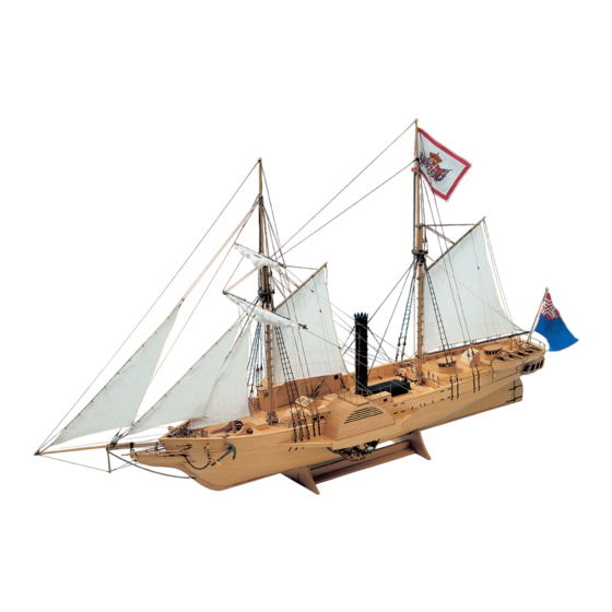
1834 in England gebaut und 1835 in den Dienst der Marine Sardiniens gestellt, ist die Gulnara ein typisches
Beispiel für den Übergang vom Segelschiff zum Dampfschiff. Als Beobachtungs-, Geleit- und Passagierschiff
tat die Gulnara Dienst für Sardinien bis 1861. Dann wurde sie von der italienischen Marine übernommen.
Die
Gulnara war mit einer oszillierenden Dampfmaschine der Firma Fawcett & Preston, Liverpool, ausgerüstet.
Ein Teil der Radschaufeln konnte bei Segelfahrt umgeklappt werden, um den Fahrtwiderstand zu verringern.
Die Baupläne sind mit Teilenummern versehen. Folgen Sie anhand der Bauanleitung diesen Nummern, und
beachten Sie unbedingt die Hinweise auf die verschiedenen Klebstoffe, soweit diese besonders erwähnt
sind.
Bevor Sie mit den Arbeiten beginnen, nummerieren Sie mit Bleistift anhand der beiliegenden verkleinerten
Schnittzeichnungen Ihre Einzelteile auf den Brettchen und beachten die angegebenen Maße.
Zuerst jedoch einige handwerkliche Hinweise.
Für den Modellbauer ist es unerlässlich, sich mit dem Beizen von Holz vertraut zu machen. Wir verwenden
im Modellbau historischer Schiffe dunkle Beizen, die den Färbungen der Originalschiffe weitestgehend
entsprechen.
Unsere Vorbereitungen zum Beizen erscheinen Ihnen vielleicht etwas umfangreich. Sie haben sich jedoch
Seite 1
© Krick Modelltechnik, Knittlingen, Dez. 2021
Werbung

Verwandte Anleitungen für krick Gulnara


Inhaltszusammenfassung für krick Gulnara
- Seite 1 Gulnara Bauanleitung 1834 in England gebaut und 1835 in den Dienst der Marine Sardiniens gestellt, ist die Gulnara ein typisches Beispiel für den Übergang vom Segelschiff zum Dampfschiff. Als Beobachtungs-, Geleit- und Passagierschiff tat die Gulnara Dienst für Sardinien bis 1861. Dann wurde sie von der italienischen Marine übernommen.
- Seite 2 9 Farbtöne zur Kontrolle zur Hand. Im Modell Gulnara beizen Sie die Teile nach dem hier aufgeführten Farbspiegel Hinter den Beizen B 1 bis B 9 sind jeweils die zu färbenden Teile mit ihren Nummern aufgeführt. Wenn für die Gulnara auch nicht alle Beiztöne gebraucht werden, so haben Sie mit unserer Methode jedoch ein wirklich brauchbares...
- Seite 3 Salzwasser. Ihr Modell wird wesentlich schöner und gepflegter aussehen als ehemals das Original. Es wird Ihnen vielleicht einen Hauch Seefahrer-Romantik aus der großen Zeit der Segelschiffe vermitteln. Wir hoffen jedenfalls, dass Ihnen Ihre Gulnara während und nach dem Bau viel Freude bereitet. Nachstehend eine Liste der wichtigsten Werkzeuge: Bastelmesser: Am besten eignen sich sog.
- Seite 4 Nadeln geheftet, jedoch untereinander gut verleimt. Beginnen Sie diese Beplankung an der Oberkante aller Spanten entlang. Sie haben damit den genauen Verlauf des Schanzkleides bereits fixiert. Verleimen Sie die Leisten des Schanzkleides untereinander sorgfältig, und Seite 4 © Krick Modelltechnik, Knittlingen, Dez. 2021...
- Seite 5 48 mm, zurecht, legen diese zwischen die beiden Radkastenwände und beplanken diese mit den Leisten 65 (Abb. 24, Bg. 4). Die fertiggestellten Radkästen werden auf die Stützbretter 55 und 56 gestellt, nach Plan Seite 5 © Krick Modelltechnik, Knittlingen, Dez. 2021...
- Seite 6 Speichen befestigt. Vorsicht! Nicht an A und B festkleben. Anschließend nehmen Sie das nur auf der unteren Seite verleimte Rad von der Welle 134 ab, drehen es um und verkleben das nunmehr unten liegende Speichenrad ebenfalls mit den Blättern. Seite 6 © Krick Modelltechnik, Knittlingen, Dez. 2021...
- Seite 7 Schichten A bis N), Pallenrad 210 (aus 5 Schichten), Spillkopf 211, Achse 212. Auf die Seitenwangen 207 werden die Poller aufgeklebt, (Abb. 49, Bg. 2 und 6), die Achse durchgesteckt und die restlichen Teile Seite 7 © Krick Modelltechnik, Knittlingen, Dez. 2021...
- Seite 8 Fenderstäbe mit den Haltebändern 384 an den Davits befestigen. Die Bootsaufhängung machen Sie aus den Teilen Block 385, Stropp 386, Bootsfall 387, Block 388, Ringhaken 389 und Stropp 390. Die Seite 8 © Krick Modelltechnik, Knittlingen, Dez. 2021...
- Seite 9 Anzahl der Blöcke, der Augbolzen und der Art der Anbringung. Aus diesem Grund verzichten wir auf eine Wiederholung des oben geschriebenen. Richten Sie sich nach den Abb. 53, 55, 64, 65 und 66, Bg. 6. Für Seite 9 © Krick Modelltechnik, Knittlingen, Dez. 2021...
- Seite 10 637 werden die Rüsteisen am Rumpf befestigt (Bogen 1). Fertigen Sie nach Abb. 85 Bg. 7 die Hilfsvorrichtung zum Ausrichten der Jungfern an. Diese Hilfsvorrichtung wird jetzt in die Rüstjungfern geschoben, und oben werden die noch nicht belegten Wantjungfern 638 Seite 10 © Krick Modelltechnik, Knittlingen, Dez. 2021...
- Seite 11 597: 251 (Abb. 53, 75, Bg. 2 und 6) 595:713-238-250 (Abb.53, 74, 75, Bg. 2, 6, 7, 8) ln das Binnenklüversegel 598 die Ringe 716 wie bei Klüversegel 592 anbringen (Abb. 74, 75, Bg. 2 und 7). Seite 11 © Krick Modelltechnik, Knittlingen, Dez. 2021...
- Seite 12 741-486-333 und beide Enden verbinden. Flagge 742 anknüpfen. Brassen für Großsegel 285: 743-582-744-580-256 (Abb. 71, Bg. 1, 2 und 7) Brasse für Marssegel 286: 745-554-746-552-257 (Abb. 70, Bg. 1, 2 und 7) Seite 12 © Krick Modelltechnik, Knittlingen, Dez. 2021...
- Seite 13 Nussbaum 1,5x8x90 mm Blende Nussbaum 1,5x8x75 mm 69+70 Maschinenr. Formklotz Balsa Beplankungsleiste Nussbaum 0,5x3x2500 mm ges. Fensterrahmenleiste Nussbaum 1x1x250 mm ges. Türrahmenleiste Nussbaum 1x1x280 mm ges. Türfüllung Tanganjika 0,5x4x200 ges. Türgriff Ms-Nagelkopf 0,6 mm Seite 13 © Krick Modelltechnik, Knittlingen, Dez. 2021...
- Seite 14 Nussbaum 1x6x42 mm Blende Edelsperrholz 1,5 mm Fenderleiste Birnbaum 1x2x310 mm Steuerpodest Edelsperrholz 1,5 mm Rahmenleiste Nussbaum 1x3x170 mm ges. Beplankungsleiste Tanganjika 0,5x7x50 mm Beplankungsleiste Tanganjika 0,5x4x600 mm ges. Steuerrad Holz-Fertigteil Seiltrommel Ms-Fertigteil Seite 14 © Krick Modelltechnik, Knittlingen, Dez. 2021...
- Seite 15 Beplankungsleiste Nussbaum 1x3x450 mm ges. Türleiste Nussbaum 1x1x50 mm ges. Sockelleiste Nussbaum 2x6x120 mm ges. Dachbeplankung Nussbaum 1x4x200 mm ges. Schiebeleiste Nussbaum 0,5x2x50 mm ges. Schiebeluke Nussbaum 1x3x100 mm ges. Gräting Holz-Fertigteil Seite 15 © Krick Modelltechnik, Knittlingen, Dez. 2021...
- Seite 16 Block Holz-Fertigteil 5 mm 326+327 Stropp Takelgarn 0,75 mm schwarz 328+329 Takel Takelgarn 0,5 mm schwarz 330-341 Block Holz-Fertigteil 3 mm 342-353 Stropp Takelgarn 0,5 mm schwarz 354-357 Block Holz-Fertigteil 5 mm Seite 16 © Krick Modelltechnik, Knittlingen, Dez. 2021...
- Seite 17 Takelgarn 1,0 mm schwarz Marsstenge Ramin 4x230 mm Eselshaupt 1 x 4 Laserteil-Schichten Mastkopf 1 x2 Laserteil-Schichten 427+428 Halterung Nussbaum 1x1x60 mm ges. 429-433 Augbolzen Ms-Fertigteil 3 mm 434+435 Doppelblock Holz-Fertigteil 5 mm Seite 17 © Krick Modelltechnik, Knittlingen, Dez. 2021...
- Seite 18 Takelgarn 0,5 mm schwarz Doppelblock Holz-Fertigteil 5 mm Stropp Takelgarn 0,5 mm schwarz Takelgarn 0,25 mm hell Klotjes Perlen Vormarsrah Ramin 4x160 mm Rahklampe Edelsperrholz 1,5 mm Mastband Ms-Fertigteil Ä Nummer Bezeichnung Anzahl Material Hinweis Seite 18 © Krick Modelltechnik, Knittlingen, Dez. 2021...
- Seite 19 Stropp Takelgarn 0,25 mm hell Niederholer Takelgarn 0,25 mm hell Halstau Takelgarn 0,5 mm schwarz Schot Takelgarn 0,25 mm hell Vorstengestagsegel Stoff-Fertigteil (Segelsatz) Block Holz-Fertigteil 3 mm Stropp Takelgarn 0,25 mm hell Seite 19 © Krick Modelltechnik, Knittlingen, Dez. 2021...
- Seite 20 Ms-Rundkopfnagel 1, 1 mm Pardunenblock 3-fach Holz-Fertigteil 5 mm Bändsel Takelgarn 0,5 mm schwarz Takel Takelgarn 0,5 mm schwarz Salingjungfer (Fock) Holz-Fertigteil 3,5 mm Rüstbeschlag Takelgarn 0,5 mm schwarz Fockstengewanten Takelgarn 0,75 mm schwarz Seite 20 © Krick Modelltechnik, Knittlingen, Dez. 2021...
- Seite 21 Takelgarn 0,5 mm hell Bändsel Takelgarn 0,25 mm hell Flaggleine Takelgarn 0,25 mm hell Ringhaken Ms-Fertigteil (Augbolzen 3 mm) Block Holz-Fertigteil 3 mm Stropp Takelgarn 0,5 mm schwarz Schot Takelgarn 0,5 mm hell Seite 21 © Krick Modelltechnik, Knittlingen, Dez. 2021...
- Seite 22 Takelgarn 0,25 mm hell Ringhaken Ms-Fertigteil (Augbolzen 3 mm) Bändsel Takelgarn 0,25 mm hell vorderes Bootslager Sperrholz 5 mm hinteres Bootslager Sperrholz 5 mm Verbindungsholm Sperrholz 5 mm Verbindungsholm Sperrholz 5 mm Seite 22 © Krick Modelltechnik, Knittlingen, Dez. 2021...
- Seite 23 Laserbrett 1 Laserbrett Balsa Seite 23 © Krick Modelltechnik, Knittlingen, Dez. 2021...
- Seite 24 Laserbrett 2 Laserbrett 3 Seite 24 © Krick Modelltechnik, Knittlingen, Dez. 2021...
- Seite 25 Modellbau vom Besten Gulnara krick • 20250 Klaus Krick Modelltechnik Gulnara Building Instructions The Gulnara is an Aviso of the sardic navy. It was built in 1834 in England and was arranged in 1835 in the ser- vice of the navy of Sardinia, it is a typical example of the transition of the sailing ship to the steamboat. The steam machine was to be considered with this ship only as a pure auxiliary impulse. The ship was still fully sailable. As an observation, escort and passenger liner did the Gulnara service for Sardinia till 1861. Then it was taken over from the Italian navy. The Gulnara was equipped with an oscillatory steam machine of the company Fawcett and Preston, Liverpool. A section of the bicycle shovels could become turned in drive under sails to reduce the journey opposition. The model box of building blocks of the Gulnara is so constructed that construction trouble could be avoided to a great extent. Therefore a kit has originated which can be built by beginners without problems successfully, as well as offers to the experienced model farmer many fine details. The frames and keel are already sawed out ready. The double planking hull is constructed from select strip material. The shovel wheels, rear gallery and many fitting parts already lie ready in the box of building blocks. Carefully contrived architect‘s plans and a detailed construction manual provide for a pleasant and uncomplicated assembly. With the slender elegant body, the interesting superstructures with boiler and high chimney, the harmo- nious suit of Sails is this model of the Gulnara is a tidbit from the pioneer‘s time of the steamboats. However, the model is not to be equipped with a working steam machine, because for this the necessary space is absent. The kit is laid out as a pure state model. Optionally a ready sewed sail sentence is available under the order No. 61913...
- Seite 26 Gulnara • Aviso 20250 Tools The basic tools you will need to build and finish the models are: 1. A modelling knife - preferably with an assortment of different shaped insertable blades and a Stanley knife which is ideal for tapering the planking strips. 2. A razor saw - for cutting the larger planks and dowels. 3. Small pliers - for bending brass and copper wire and also to help push in pins for the planking. 4. A range of twist drills from 0.5 - 3 mm and a pin vice. 5. A David plane- for chamfering planks and shaping the masts and yards. 6. A selection of different profile needle files: flat, round, half round, triangular etc. 7. Tweezers. Abrasive paper You will need a sanding block and different grades of glass paper, from coarse to fine, working down through the grades until the desired finish is attained. Adhesives 1. White PVA (Evostick Resin W) is the main wood adhesive that is required, but remember that the total cure time is about 24 hours. 2. Super glue for dissimilar materials, and also it can be used to stiffen the ends of rigging, making it easier to pull through the blocks and dead eyes. 3. Epoxy resin is the best for the permanent fitting if the stem quarter galleries and figurehead, and also the brass funnel to the boiler. 4. Contact or impact adhesive - this is an alternative for the second planking of the hull instead of PVA and ...
- Seite 27 Gulnara • Aviso 20250 Instructions for the paddle steamer Gulnara. It is important to familiarise your self with all the parts in the kit by having a thorough look through the plans and parts list which is at the end of the German translation of the instructions, these give the lengths, widths and diame- ters of the parts you will need. Always use these instructions in conjunction with the plans and drawings. 1. Build a cradle for the keel as shown on plan or ‚Boden 3‘. The material for this is not supplied in the kit. Ideally the base should be a plywood sheet (approx. 15x200x300 mm). 5 mm for the supports and two hardwood strips (approx. 10 x 10 mm) and construct as shown on the plan. 2. Carefully cut out the keel (no.1) from the plywood sheet and insert into the cradle. 3. Sort out the 13 bulkheads (they should be numbered) and dry fit them. They will probably need additional filling as some slots may be too tight. 4. Refer to plan 3, drawing (drg) 3 to see how parts 15 and 16 are fitted into bulkhead 10. Also refer to supplemen- tary drg. 1, figure (fig) 1. for the removal of the top bulkhead frames from bulkhead 7. 5. Using a T-square glue the bulkheads with White PV A in the slots and make sure that the bulkheads are at exactly 90°. Temporarily place the two deck pieces no. 19 and no. 20 on the bulkheads to ensure that everything is lined up correctly whilst drying, and leave overnight until the glue is thoroughly dry. Then take the two pieces off again. Note: it is wise to mark out and draw the centreline on the decks for the deck planking at a later stage. 6. Refer again to fig. 2 on the supplementary drgs. for the slight modification of the two parts, no. 17. After you have reshaped the ends of no. 17 insert and glue them in their respective slots between bulkheads 6, 7 and 8 and then insert the brass tube no. 18 (4mm dia) and glue using epoxy resin. The tube should be just inside the width of the bulkheads. Refer to plan 3, drg. 4 for the correct placement. 7. Glue decks 19 and 20 in place as shown on plan 3, drg. 5. You may have to temporarily pin the decks at the edges because of the camber or curve of the decks. 8. Refer to plan 3, drg.3 for the correct placement of part nos. 33 and 34. Number 33 is placed nearest bulkhead 8 and no. 34 by bulkhead 6. Next add no.35 which is strip wood measuring 3x3mm and should be cut 2.5 cm long and placed as shown on the drawing. 9. Sort out the bow and stem blocks nos. 21 to 32 referring to plan 2 and plan 3 nos. 6-7 and 11 for the correct placing of these parts. The blocks at the bow are triangular in shape and slightly rounded on the one edge. When gluing the blocks make sure that they are tightly butted against the keel and bulkhead, the same applies to the stem blocks. After the glue has dried thoroughly very carefully sand the ‚stepped‘ blocks to shape, along with the edges of the bulkheads. A lot of care and patience is needed to shape the stem and bow blocks and ...
- Seite 28 Gulnara • Aviso 20250 Pin and glue the first plank untaperred, starting from bow to stem. The rest of the planks will have to be tapered as already described . The planks should run as naturally as possible and should not be forced in to place. As you work your way down, you will find that at the stem there will be a few triangular shaped gaps, to fill these in just mark the gap pout on scrap material and just fix them into the gaps, (these are called stealers and are present on full size ships). Once the bottom hull planking is complete plank the area above the deck only minor tapering is needed towards the bow area. Leave the planked hull for about 24 hours before sanding, using course grit and working down to fine grit. Sand in a well ventilated area, or preferably outside as there will be a large amount of dust. Start the second planking (walnut strip 1x5x830 mm) in exactly the same way as the first, but taking more care to avoid gaps between the planks as these will show severely. the key word is patience ifyou rush the chan- ces are that your efforts will be wasted. The whole area of the plank should be glued to the first planking and pinned where necessary. Do not drive the pins all the way down except perhaps at the stem where the twisted planks have the chance of springing out of place while the glue is still curing. When the glue is thoroughly dry remove all pins and to start to sand with medium grade abrasive paper and working down to finer grades. Remember that the second planking is only 1 mm thick so sand with care with the grain to avoid scratches on the planks. 11. Plank the stern with 1x5 mm walnut strip as shown on plan 4 drg. 14 and then sand. Use the same size walnut strip to plank the stern post, keel and bow as shown on plan 1. 12. Carefully take off all the bulkhead frames above the deck and sand smooth the deck as shown on plan 4 no,18. Sand the inside ofthe bulwarks until smooth and plank using 5x1 mm walnut strip. 13. Refer to plan 2 and plan 4 no. 5, 15 and 16 for the correct placings of no 45 (1x2 mm) bulwark frames (3x1 mm), no. 53 1x2 mm strip which is place above bulwark frames and level with top of bulwark, bulwark ports and scuppers (no 40). 14. Start the deck planking (no.51, 0.5x4 mm) at the centre line of the false deck and work outwards carefully marking out and trimming the planks as you the reach the edge of no. 45, the margin plank. After you have planked the decks varnish them to seal the grain. 15. Refer to plans 1 and 2 for the correct placing of no. 89 the stern transam and no. 88 the stern galleries. fix no.89 in place first and then make the window frames using 1x1 mm strip. Paint the area inside the frames black (Humbrol paints no. 33 ). The white metal quarter galleries may need careful filling for a close fit to the side of the hull and the back of the stern transam. Care and attention is needed to properly do this. Again paint the inside of the window frames matt black and the outside oak or Humbrol paint no 94. Glue the white metal galleries with epoxy resin. To avoid the parts slipping or moving during curing, you could put a spot or two of superglue on the castings to keep them in place whilst the resin dries.
- Seite 29 Gulnara • Aviso 20250 When the paddle wheel assembly is completed , fix them in place with the paddle wheel housings. Slide the brass rod no 134- 3 mm diameter x 235 mm length ) through no 18 inside the hull. Fit and glue the first paddle wheel in place, put the housing over the top of the wheel, then slide and flue the housing into place. The same applies to the other side except glue the paddle wheel in place last. Cut out the platforms (no 80 - 2 ) which fit on top of the paddle wheel housing, plank, mark and drill the holes for the brass stanchions. The platform is supported by 3x3 mm strip running underneath the edge of the length of the platforms. Refer to plan l and plan 5 for the correct placing of no 67 , 68 and 138. Carefully mark out and fix the 2x1 mm wales along the sides of the ship. 18. Mark out, cut and shape the bulwark railings (no 85 -86) use plan 4 no 15 and 17 to show how they are shaped and put into place. make the pin rails 102, 104, 106, and supports. 103 , 105, 107. drill the holes out for the belaying pins before fixing them to the hull. Make and fix the rudder in place as shown on plan 5, no 31. and plan 1. 19. Refer to plans 5 and 6 and make the various deck housing, hatches, gratings etc., as shown, The brass funnel needs to be carefully marked out for the drilling of the holes for the eylets (no. 184). Mark a straight line down the funnel and using the plans mark out where the holes have to be drilled. Using a 0.50 mm drill bit. It is best to punch a slight dent in the area that is to be drilled to avoid the drill slipping . Glue or solder the six brass rings that fit around the funnel, then epoxy or solder part 183, the photo etched funnel top when the glue is dry, gently pull the tops of the funnel top out slightly with a small pair of pliers. Make the boiler with the abachi block. Refer to plan 5. no. 42 for the correct shape which is easily obtained with the use of a sanding block. Next, place half of the base of the funnel on the edge of the boiler and care- fully mark out the semi-circle. Fret out the area well inside the marked area and file out with semi-circular file, constantly checking for a correct fit to the funnel. Mark out and drill the areas where no 180 fits, these are pins at 0.60 dia. and then make the doors on the side from 1x8 mm strip. Glue the funnel to the boiler using epoxy resin. Once the glue has dried paint the whole unit first with a matt black undercoat and then two coats of satin black (Humbrol paint no 85.) to give a metallic look. Because of the deck camber some of the assemblies will not lie flat on the deck, to overcome this place a piece of abrasive paper on the deck and sand the assemby using a forward and backward motion in the middle of the deck until the curve is achieved. 20. Once all deck fittings railings, cleats, etc., shown on plan 5 and 6 have been made and varnished glue them to their respective positions as shown on the plans. Take the boat hooks no 380 out of the housings until the rigging is complete as they can interfere with the rigging process. 21. Glue the two halves of the figure head together and glue it onto the end of the prow as shown on plan 1. Paint ...
- Seite 30 Gulnara • Aviso 20250 dia. and cut to 40 mm in length. Drill and insert 0.50 mm brass rod cut to about a centimetre, drill another hole on the bottom of the bowsprit capping and super glue the dolphin striker in place. Add the dead eyes and block and eyelet‘s to the bow sprite as shown on the plans 238, 239, 404 are 3 mm single blocks. 242, 243 are 3.5 mm dia deadeyes and 402 is a closed heart block. The black hemp to seize these blocks to the bowsprit is 0.50 mm. Drill a 2 mm hole as shown on the end of the bowsprit, make the two bitts. (no. 221 on plan 2 ) using 5x5 mm walnut cuts to 25 mm in length and shaped at the top as shown using a needle file. Drill 2mm holes as shown on the plan. Push the bowsprit through the hole at the front of the ship until the holes at the end of the bowsprit meet with those on the bitts, and then insert 2 mm brass rod about 15 mm length through the holes to secure the bowsprit. 24. Make the masts and topmasts with the ramin dowel as shown in detail on plan 8. Note that the upper section at the lower masts is squared off and the edges slightly chamfered. Use a flat file to make the square section, and also for the slots at the bottom of the main masts as shown on the drawings. When the tops have been shaped, cut out and glue the cheeks (no 467 on the main mast, and no 416 on the slightly smaller formast). Refer to plan 8 , numbers 63 and 66 for the correct assembly and placing of fittings for the mast caps and tops. Be careful when drilling the holes for the deadeye strops as the wood can split easily. To reduce this risk, cover the area in watered down white PVA to strengthen the assembly, and drill when dry then paint overall in black. Cut nos 452 and 453 from the photo etched sheet and insert the belaying pins in the holes. The holes may need filing out with a round needle file before inserting the belaying pins. Slide nos. 452 and 453 into their respective positions on the two masts as shown on plan 8. Stain the masts with walnut wood dye and then tie all blocks in place as shown. 25. Mark out, cut and taper to size the three gaff yards and add the blocks, eylets gaff jaws and parral beads as shown on plan 8, numbers 67 , 68 and 69. To fit gaff jaws (no 501, 515 and 524 ), file a slot at the end of the yard with a small flat file and insert and flue into place. Drill a hole 0.50 at either side of the jaws for the parral bead rope. PLEASE NOTE IF YOU INTEND TO RIG SAILS ON YOUR MODEL, PUT THEM ONTO THEIR RESPECTIVE YARDS AND BOOMS BEFORE YOU ATTACH THEM TO THE MASTS ...
- Seite 31 Gulnara • Aviso 20250 Supplementary drawing 1...
- Seite 32 Gulnara • Aviso 20250 Supplementary drawing 2 Klaus Krick Modelltechnik • Postfach 11 3 8 • D-75 4 34 Knittlingen Telefon 0 70 43 / 9 35 10 • Telefax 0 70 43 / 3 18 38 • www.krick-modell.de ...
- Seite 33 Gulnara • Aviso 20250 Supplementary drawing 3...
- Seite 34 Gulnara • Aviso 20250 Supplementary drawing 4 Klaus Krick Modelltechnik • Postfach 11 3 8 • D-75 4 34 Knittlingen Telefon 0 70 43 / 9 35 10 • Telefax 0 70 43 / 3 18 38 • www.krick-modell.de ...
- Seite 35 Gulnara • Aviso 20250 Supplementary drawing 5...
- Seite 36 • Historisch• Historic• Historique• Die Gulnars ist ein Aviso der sardischen Marine. Sie wurde 1834 in England gebaut und 1835 in den Dienst der Marine Sardiniens gestellt, sie ist ein typisches Beispiel für den Übergang vom Segelschiff zum Dampfschiff. Die Dampfmaschine war bei diesem Schiff nur als reiner Hilfsantrieb zu betrachten. Das Schiff war noch voll segelbar. Als Beobachtungs-, Geleit und Passagierschiff tat die Gulnara Dienst für Sardinien bis 1861. Dann wurde sie von der italienischen Marine übernommen. Die Gulnara war mit einer oszillierenden Dampfmaschine der Firma Fawcett & Preston, Liverpool, ausgerüstet. Ein Teil der Radschaufeln konnte bei Fahrt unter Segeln umgeschwenkt werden, um den Fahrtwiderstand zu verrin- gern. The Gulnara is an Aviso of the sardic navy. It was built in 1834 in England and was arranged in 1835 in the ser- vice of the navy of Sardinia, it is a typical example of the transition of the sailing ship to the steamboat. The steam machine was to be considered with this ship only as a pure auxiliary impulse. The ship was still fully sailable. As an observation, escort and passenger liner did the Gulnara service for Sardinia till 1861. Then it was taken over from the Italian navy. The Gulnara was equipped with an oscillatory steam machine of the company Fawcett and Preston, Liverpool. A section of the bicycle shovels could become turned in drive under sails to reduce the journey opposition. Modellbau vom Besten krick Klaus Krick Modelltechnik Inhaber Matthias Krick Postfach 11 3 8 · D-75 4 34 Knittlingen Industriestr. 1· D-75 4 38 Knittlingen Telefon 0 70 43 / 9 35 10 Telefax 0 70 43 / 3 18 38 www.krick-modell.de Klaus Krick Modelltechnik • Postfach 11 3 8 • D-75 4 34 Knittlingen Telefon 0 70 43 / 9 35 10 • Telefax 0 70 43 / 3 18 38 • www.krick-modell.de ...