Herunterladen Diese Seite drucken

Werbung

Verfügbare Sprachen

Verfügbare Sprachen

Wilo-Stratos / -D / -Z
D
Einbau- und Betriebsanleitung
GB
Installation and Operating Instructions
For latest prices and delivery to your door visit MyTub Ltd - 0845 303 8383 - www.mytub
F
Notice de montage et de mise en service
NL
Montage- en bedieningsvoorschriften

Werbung

loading

Inhaltszusammenfassung für Wilo Stratos Serie

  • Seite 1 Wilo-Stratos / -D / -Z Einbau- und Betriebsanleitung Notice de montage et de mise en service Installation and Operating Instructions Montage- en bedieningsvoorschriften For latest prices and delivery to your door visit MyTub Ltd - 0845 303 8383 - www.mytub...
  • Seite 2 Fig. 1a Fig. 1b Fig. 2a Fig. 2b Fig. 3 For latest prices and delivery to your door visit MyTub Ltd - 0845 303 8383 - www.mytub...
  • Seite 3 Fig. 5 Fig. 6 Fig. 4 Fig. 7 For latest prices and delivery to your door visit MyTub Ltd - 0845 303 8383 - www.mytub...
  • Seite 4 Fig. 8 Fig. 9 Fig. 10 Fig. 11 Fig. 12 For latest prices and delivery to your door visit MyTub Ltd - 0845 303 8383 - www.mytub...
  • Seite 5 Fig. 13 Fig. 14 For latest prices and delivery to your door visit MyTub Ltd - 0845 303 8383 - www.mytub...
  • Seite 6 Fig. 15 Fig. 15 „LON“ Fig. 15 „PLR“ Fig. 15 „SBM“ Fig. 15 „Ext. Min“ Fig. 15 „Ext. Off“ For latest prices and delivery to your door visit MyTub Ltd - 0845 303 8383 - www.mytub...
  • Seite 7 Einbau- und Betriebsanleitung ……002 Installation and Operating Instructions ……029 Notice de montage et de mise en service ……056 Montage- en bedieningsvoorschriften ……083 For latest prices and delivery to your door visit MyTub Ltd - 0845 303 8383 - www.mytub...
  • Seite 8 8.2 Warnmeldungen ............... . IF-Module für Wilo-Stratos/Stratos-D/Stratos-Z ....... . .
  • Seite 9 1. Allgemeines Störfestigkeit: EN 61000-6-2, ehemals EN 50082-2 (Industrie-Standard) Verwendungszweck Schalldruckpegel: < 54 dB(A) Die Hocheffizienz-Pumpen der Baureihe Wilo-Stratos Temperaturbereich des Fördermediums: -10°C bis werden zur Förderung von Flüssigkeiten in +110°C Warmwasser-Heizungsanlagen Max. Umgebungstemperatur: +40°C Kühl- und Kaltwasserkreisläufen Max. Betriebsdruck an der Pumpe: siehe Typenschild.
  • Seite 10 
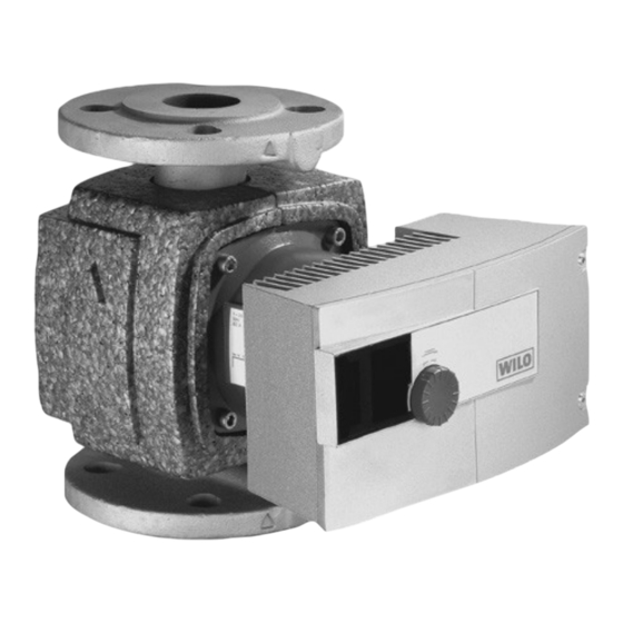
Die Nichtbeachtung der Sicherheitshinweise kann eine Beschreibung der Pumpe (Bilder 1a, 1b) Gefährdung für Personen und Pumpe/Anlage zur Folge Die Hocheffizienz-Pumpe Wilo-Stratos ist eine haben. Die Nichtbeachtung der Sicherheitshinweise Baureihe von Nassläuferpumpen mit „E-lectronic kann zum Verlust jeglicher Schadenersatzansprüche Commutated Motor“ (ECM)-Technologie und inte- führen.
  • Seite 11 Diese Einstellung stellt sicher, dass Die Hocheffizienz-Pumpen der Baureihe Wilo- Energieverbrauch der Pumpe auf ein Minimum redu- Stratos-Z sind durch Materialauswahl und Kon- ziert wird und in den meisten Fällen die optimale struktion speziell auf die Betriebsverhältnisse in Einstellung ist.
  • Seite 12 DEUTSCH Doppelpumpenbetrieb vom IR-Monitor angepeilt werden. Ist die Verbindung zum IR-Monitor hergestellt, so leuchtet im IR-Fenster Doppelpumpen oder zwei korrespondierende die grüne LED zur Bestätigung der IR-Kommunikation, Einzelpumpen können einem integrierten und zwar von allen Pumpen, die gleichzeitig mit dem Doppelpumpenmanagement nachgerüstet werden.
  • Seite 13 DEUTSCH Differenzdruck-Sollwert ist auf H Pumpe läuft als Slave-Pumpe. An = 5,0 m eingestellt. der Lageeinstellung der Displayanzeige kann keine Veränderung vorgenommen Regelungsart ∆ p-v, Regelung auf werden. variablen Differenzdruck-Sollwert Doppelpumpe läuft im (Bild 8). Spitzenlastbetrieb Regelungsart ∆ p-c, Regelung auf (Master + Slave) konstanten Doppelpumpe läuft im Haupt-...
  • Seite 14 DEUTSCH Displaylage: Lageeinstellung in Menüpunkt 3 horizontal vertikal For latest prices and delivery to your door visit MyTub Ltd - 0845 303 8383 - www.mytub...
  • Seite 15 DEUTSCH Bei der Bedienung des Displays der Einzelpumpe erscheinen nacheinander folgende Menüs: (horizontale Darstellung der Displayanzeige) Einzelpumpenbetrieb: Einstellung bei Erstinbetriebnahme / Menüfolge bei laufendem Betrieb LC-Display Einstellung Beim Einschalten des Moduls erscheinen im Display für 2 s alle Symbole. Danach stellt sich die aktuelle Einstellung ein.
  • Seite 16 DEUTSCH LC-Display Einstellung Die aktuell eingestellte Regelungsart leuchtet. Durch Drehen des Stellknopfes können andere Regelungsarten angewählt werden. Die neu angewählte Regelungsart leuchtet. Durch Knopfdruck wird die neue Regelungsart übernom- men und ins nächste Menü geschaltet. Menüpunkt erscheint nur, wenn ein IF-Modul Stratos mit Eingang 0...10V gesteckt wurde.
  • Seite 17 DEUTSCH LC-Display Einstellung Entweder blinken auto Absenkbetrieb freigegeben. In Menüpunkt steht dann „auto “ während des autom. Regelbetriebes oder „auto “ wäh- rend des Absenkbetriebes. normaler Regelbetrieb, Absenkbetrieb gesperrt. Der Menüpunkt ist dann ohne Symbol. Eine der beiden Einstellungen anwählen und übernehmen.
  • Seite 18 DEUTSCH Doppelpumpenbetrieb: Einstellung bei Erstinbetriebnahme (vertikale Displayanzeige) LC-Display Einstellung Beim Einschalten des Moduls erscheinen im Display für 2 s alle Symbole. Danach erscheint das Menü 1a . Auf dem Display beider Pumpen wird das Symbol MA = Master ange- zeigt.Wird keine Einstellung vorgenommen, laufen beide Pumpen mit konstanter Drehzahl (Hs = | H bei Q = 0).
  • Seite 19 DEUTSCH Doppelpumpenbetrieb: Menüfolge bei laufendem Betrieb: Beim Einschalten des Moduls erscheinen im Display für 2 s alle Symbole . Danach stellt sich die ak- tuelle Einstellung ein. Beim „Blättern“ am Display MA erscheint die gleiche Menüfolge bei der Einzelpumpe. Danach erscheint das Menü MA als Daueranzeige. LC-Display Einstellung ACHTUNG! Durch...
  • Seite 20 DEUTSCH Prioritäten bei der Bedienung von Zubehör Pumpe, LON, PLR, IR-Monitor IF-Module Stratos PLR, LON, Ext.Off, Ext.Min, SBM Die Anzeige von Störungen (Menü 10) incl. IR-Monitor Störquittierung hat die höchste Priorität. Das bedeu- tet, daß Störungen vorrangig auf dem Display der Pumpe erscheinen und beseitigt bzw.
  • Seite 21 DEUTSCH Montage kann sich die Schrauben- Regelmodul vom Motor abziehen (Pos.5), mutter im Langloch verhaken. Montage in umgekehrter Reihenfolge. Bei generatorischem Betrieb der Pumpe Dadurch kann, wegen unzureichender (Antrieb des Rotors durch Vordruckpumpe) Vorspannung der Schrauben, die entsteht an den Motorklemmen nach Funktionsfähigkeit der Flanschver- Abnehmen des Regelmoduls eine gefährli- bindung beeinträchtigt werden.
  • Seite 22 5.1.3 Isolierung der Pumpe in Kälte-/ dem Anziehen dicht ist. Nicht be- Klimaanlagen nutzte Kabelverschraubungen sind Die Baureihe Wilo-Stratos ist für den Einsatz in Kälte- mit einer Kunststoffscheibe ver- und Klimaanlagen mit Fördermediumtemperaturen bis schlossen. Diese Scheibe darf nicht –10°C geeignet. In diesen Einsatzfällen ist auch inter- entfernt werden.
  • Seite 23 DEUTSCH einzelnen Kabelverschraubungen belegt werden Wird bei einer Doppelpumpe ein ein- ACHTUNG! können. Dabei ist die DIN EN 60204-1 (VDE 0113, zelner Motor spannungsfrei geschal- Bl.1) zu beachten: tet, ist das integrierte Doppelpum- Abs. 14.1.3 sinngemäß: Leiter von verschiedenen penmanagement ausser Funktion. Stromkreisen dürfen zum selben Mehrleiterkabel Schalthäufigkeit: gehören, wenn die Isolation der höchsten in dem...
  • Seite 24 DEUTSCH Regelungsarten ∆p-c, ∆p-v und ∆p-T: ∆p-c (Bild 9) ∆p-v (Bild 8) ∆p-T (Bild 10) Betriebspunkt auf Vom Betriebspunkt aus nach links zeichnen. Sollwert Einstellungen sind unter Max-Kennlinie Hs ablesen und die Pumpe auf diesen Wert einstellen. Berücksichtigung der Anlagenverhältnisse über LON-Bus oder mit dem IR-Monitor vom Kundendienst vorzuneh-...
  • Seite 25 DEUTSCH empfohlene Anlagentyp Systembedingungen Regelungsart Heizungs-/Lüftungs-/Klimaanlagen mit 1. Zweirohrsysteme mit Thermostat- Widerstand im Erzeuger-/Verteilkreis ≤ /Zonenventilen und hoher Verbraucherautorität 25% des Widerstandes im Übergabeteil ≤2m (Raumheizkörper + Thermostatventil) Umgebaute Schwerkraftanlagen Umrüstung auf große Temperaturspreizung (z.B. Fernwärme) Geringe Druckverluste in den Anlagenteilen, die vom Gesamtvolumenstrom durchflossen werden (Kessel/Kältemaschine, evtl Wärmetauscher, ∆p-c...
  • Seite 26 DEUTSCH 7 Wartung/Service Vor Wartung- oder Instandsetzungsarbei- ten Anlage spannungsfrei schalten und ge- gen unbefugtes Wiedereinschalten sichern. hohen Wassertemperaturen Systemdrücken Pumpe vorher abkühlen lassen. Verbrühungsgefahr! Wird bei Service- oder Instandset- ACHTUNG! zungsarbeiten der Motorkopf vom Pumpengehäuse getrennt, muß der O-Ring, der sich zwischen Motorkopf und Pumpengehäuse befindet, durch einen neuen ersetzt werden.
  • Seite 27 DEUTSCH Störmeldungen: Warnmeldungen: Störung Störung siehe Tabelle Pumpe Code-Nr. schaltet Störmelde-LED „ein“ DP: Umschaltung auf aus so- PUMPE schaltet aus andere Pumpe lange Wartezeit 5 Minuten Kein manueller Reset Fehler möglich Betriebsmel- anliegt derelais SBM öffnet beim IF-Modul Stratos Autostart PUMPE schaltet ein länger als Regelbeltrieb...
  • Seite 28 DEUTSCH Tabelle I Störung Ursache Abhilfe Pumpe läuft bei eingeschalteter Elektrische Sicherung defekt, Sicherungen überprüfen Stromzufuhr nicht Pumpe hat keine Spannung, Spannungsunterbrechung beheben Pumpe macht Geräusche Kavitation durch Systemvordruck innerhalb des unzureichenden Vorlaufdruck zulässigen Bereiches erhöhen Förderhöheneinstellung überprüfen evtl. niedrigere Höhe einstellen Störmeldungen: Stör-LED „Dauerlicht“...
  • Seite 29 Master und Slave festlegen eingestellt Lässt sich die Betriebsstörung nicht beheben, wenden Sie sich bitte an Ihren Sanitär- und Heizungsfach- handwerker oder an den WILO-Kundendienst. For latest prices and delivery to your door visit MyTub Ltd - 0845 303 8383 - www.mytub...
  • Seite 30 Serielle digitale Schnittstelle PLR zum Anschluss an die Spannung 0...10V vor- Schnittstellenkonverter oder firmenspezifische gegeben wird (Bild 12). Koppelmodule: Wilo-spezifische Punkt-zu-Punkt-Verbindung mit Wilo-Protokoll. Die Klemmen sind verdrehsicher und fremdspannungsfest. For latest prices and delivery to your door visit MyTub Ltd - 0845 303 8383 - www.mytub...
  • Seite 31 DEUTSCH Darstellung im Display: Eingang für potentialfreien Öffner mit der Funktion Ext. Min: max. Kabellänge: 100 m, 2-adriges Kabel, geschirmt Klemmenquerschnitt: max. 1,5 mm Ausgang als potentialfreier Schließer mit der Funktion SBM: max. Kabellänge: 100 m, 2-adriges Kabel, nicht geschirmt Klemmenquerschnitt: max.
  • Seite 32 DEUTSCH Modultyp Funktion Serielle digitale Schnittstelle PLR zum Anschluss an die 1xMA Gebäudeautomation GA über Wilo-Schnittstellen-Konverter oder 1xSL bauseitige Koppelmodule Serielle digitale Schnittstelle LON zum Anschluss an LONWORKS- 1xSL 1xMA Netzwerke, Transceiver FTT 10A Eingang für potentialfreien Öffner mit der Funktion „Ext. Aus“...
  • Seite 33 DEUTSCH Doppelpumpen-Betriebsart Haupt-/Reservebetrieb Additionsbetrieb Funktion 0…10 V Drehzahlfernverstellung (DDC) Grundlastpumpe folgt dem Beide Pumpen folgen mit 0...1 V: Spannungssignal gleicher Drehzahl dem 1...3 V: Min-Drehzahl Grundlastpumpentausch nach 24 Spannungssignal 3...10 V: ...n Betriebsstunden Sollwertfernverstellung Grundlastpumpe regelt Wirkungsgradoptimierte Zu- und 0...1 V: Differenzdruck Abschaltung der 1...3 V:...
  • Seite 34 DEUTSCH Kommunikationskabel (abgesetzt) durch PG- Verschraubung führen, Drähte des Kommunikationskabels am IF-Modul auflegen (IF-Modul ist noch nicht gesteckt.), Drähte des Kommunikationskabels zu einer Schlaufe legen und IF-Modul montieren. Klemmenkastendeckel mit den Laschen in die Aussparungen einhaken und zuschrauben: siehe Bild 4 IF-Modul Stratos LON: Ein Aufkleber mit der Neuron- ID verbleibt auf dem IF-Modul, der andere Aufkleber kann z.B.
  • Seite 35 8.2 Warning messages ............... . . IF modules for Wilo Stratos/Stratos-D/Stratos-Z ........
  • Seite 36 System of protection: IP 44 up to Tmax = 80°C, 24 °e (Stratos-Z only) Insulation class: If other media are used, release by Wilo is required. Motor protection: standard built-in full motor pro- When ordering spare parts, please give all the informa- tection tion on the unit rating plate.
  • Seite 37 4 Product and accessory description ATTENTION! Pump description (figs 1a, 1b) Staff training The Wilo Stratos high efficiency pump is a series of The personnel installing the pump must have the ap- glandless pumps with Electronic Commutated Motor propriate qualifications for this work.
  • Seite 38 ENGLISH 4.1.1 Differential-pressure control systems 4.1.3 General pump functions The control systems which can be selected are: The pumps are fitted with an electronic overload ∆p-v: The electronics increase the pump's differen- protection system which switches the pump off tial pressure set value in a straight line between | Hs should it become overloaded.
  • Seite 39 ENGLISH her energy saving is reached by this mode of opera- Symbol Description of possible operating tion. conditions Duty/Standby mode: Each of the two pumps produ- Standard mode; automatic switch- ces the design delivery rate. The other pump can be auto over to night setback mode is used in the event of the first pump malfunctioning or...
  • Seite 40 ENGLISH Operating the tuning button: (Figure 1a, pos.1.3) In regulator mode, the speed or 10 V Starting from the basic setting, the setting menus are nominal lift of operating mode ∆ p-c or ∆ p-v the pump is set via selected one after the other in a fixed order by pressing the button (in 1st menu: press for more than 1 s).
  • Seite 41 ENGLISH Display position: Position setting in menu point 3 horizontal vertical For latest prices and delivery to your door visit MyTub Ltd - 0845 303 8383 - www.mytub...
  • Seite 42 ENGLISH If the pump display is operated further, the following menus appear in succession: (horizontal representation of display) Single-pump mode: Setting when first used / Menu order during standard use LC display Setting After switching on the module, all symbols appear on the display for 2 seconds.
  • Seite 43 ENGLISH LC display Setting The currently set control system blinks. By turning the tuning button other control systems can be selected. The new selected control system blinks. Pressing the button stores the new control system and switches to the next menu. Menu point only appears if a Stratos IF module was inserted with input 0...10V.
  • Seite 44 ENGLISH LC display Setting Either flashauto auto Automatic night-setback. Menu point then shows "auto “ during autom. standard mode or "auto “ during automa- tic night-setback. f normal standard mode, automatic night-setback blocked. Menu point does not contain any symbol. call up one of the two settings and store.
  • Seite 45 ENGLISH Double pump mode: Setting when starting up for the first time (vertical display) LC display Setting When the module is switched on all symbols appear in the display for 2 s. Menu 1a then appears. The symbol MA = Master blinks on the display of both pumps.Should the settings not be altered, both pumps will run at a constant speed (Hs = | H where Q = 0).
  • Seite 46 ENGLISH Double pump mode: Menu order during normal use: After switching on the module, all symbols appear on the display for 2 seconds. The current setting then sets itself. When "scrolling" in the MA display the same menu order … appears as for the single pump.
  • Seite 47 ENGLISH Important points on the operation of Installation and Operating Instructions the pump, PLR, LON, IR monitor Accessories The display of errors (menu 10) incl. error acknowledg- Stratos IF module PLR, LON, Ext.Off, Ext.Min, SBM ment has the highest priority. What this means is that IR monitor errors take precedence on the pump's display and that they must be acknowledged and removed.
  • Seite 48 ENGLISH 2. The enclosed plain washers must be used bet- Loosen 2 M5 hexagon socket screws (SW4) (pos. 4), ween the screw/nut head and the combi flange Remove control module from motor (pos. 5), (fig. 3, pos. 1). To install, reverse the above sequence. Safety elements (e.g spring rings) are ATTENTION! If the pump is running off a generator (ro-...
  • Seite 49 When using the pump in systems where the water conditioning systems temperature exceeds 90 °C, a connecting pipe with The Wilo Stratos series is suitable for use in refrigera- corresponding heat resistance must be used. ting and air-conditioning systems with flow medium The connecting lead must be laid in such a way that temperatures up to -10 °C.
  • Seite 50 ENGLISH Para. 14.1.3 accordingly: Conductors of different circuits may belong to the same multi-conductor cable if the insulation of the highest voltage occur- ring in the cable suffices. Para. 4.4.2 accordingly: In the case of possible func- tional interference due to EMC, signal lines with a low power cable level should be separated.
  • Seite 51 ENGLISH Control systems ∆p-c, ∆p-v and ∆p-T: ∆p-c (Fig. 9) ∆p-v (Fig. 8) ∆p-T (Fig. 10) Operating point Draw a line from the operating point to the left. Read Settings are to be made on max. set value Hs and set the pump in accordance with this by Customer Services characteristic value.
  • Seite 52 ENGLISH Recommended Unit type System conditions control system Heating-/ventilation- and air conditio- 1. Two-pipe systems with thermostatic/zone valves ning systems with a resistor in the gene- and high consumer authority rator/distributor circuit ≤ 25% of the re- ≤ 2m sistance in the transfer part (heating Converted gravity systems radiator + thermostatic valve) Retrofitting to large temperature spread (e.g.
  • Seite 53 ENGLISH 7 Maintenance/service Prior to maintenance or repair work, turn off the pump and ensure that it is not tur- ned on by unauthorised personnel. In the event of high temperatures and high system pressure, the pumps should be al- lowed to cool down Danger of liquid boi- ling over! Risk of scalding! If the motor head is separated from...
  • Seite 54 ENGLISH Error messages: Warning messages: Error Error table I Code no. Pump Error LED „on“ shuts DP: switch too diff. down pump PUMP shuts down while No manual Waiting time 5 min reset possible error Operating relay present SBM opens for Stratos IF module SBM Autostart PUMP switches on...
  • Seite 55 ENGLISH Table I Problem cause remedies Pump does not run with Electric fuse faulty, Check fuse switched on power Pump has no power Rectify interruption to power Noisy pump operation Cavitation due to insufficient Increase system admission pressure admission pressure within permissible range Check pump lift setting, if nec.
  • Seite 56 Specify master and slave not set If the fault cannot be remedied, please contact your local plumbing and heating specialist or WILO customer services. For latest prices and delivery to your door visit MyTub Ltd - 0845 303 8383 - www.mytub...
  • Seite 57 ENGLISH 9 IF modules for Wilo The terminals are locked and resistant to external voltage. Stratos/Stratos-D/ Dielectric strength: 250 V AC Stratos-Z Input for potential-free closed contact with the function Ext. Off Functions of the Stratos IF modules in contact closed: Pump works in standard mode.
  • Seite 58 ENGLISH Representation in max. cable length: 100 m, 2-core cable, not shiel- display: Terminal cross-section: max. 1,5 mm Control input 0...10V: max. cable length: 25 m, 2-core cable, shielded Terminal cross-section: max. 1,5 mm DP interface max. cable length: 2.5 m, 2-core cable, not shielded Terminal cross-section: max.
  • Seite 59 ENGLISH Modultype Function Serial digital interface PLR for connecting to the 1xMA building management system BMS via Wilo 1xSL interface converter or customer's coupling module Serial digital interface LON for connecting to 1xSL 1xMA LONWORKS networks, transceiver FTT 10A Input for potential-free closed contact with the function "Ext.
  • Seite 60 ENGLISH Double pump mode Duty/Standby mode: Duty/Standby mode: Function 0…10 V Remote speed adjustment (DDC) Basic load pump follows the vol- Both pumps follow the voltage 0...1 V: tage signal signal at the same speed 1...3 V: Min speed Basic load pump swap after 24 3...10 V: ...n operating hours...
  • Seite 61 ENGLISH Attach terminal box lid with the clips in the recesses and screw down: see fig. 4). Stratos LON IF module: One sticker with the Neuron ID remains on the IF module, the other can e.g. be af- fixed to the side of the associated pump in the plant plan.
  • Seite 62 Modules IF pour Wilo-Stratos/Stratos-D/Stratos-Z ........
  • Seite 63 Fourchette de températures du fluide véhiculé : de Applications -10°C à +110°C Les pompes à haut rendement de la série Wilo-Stratos Température ambiante maximale : 40°C sont conçues pour véhiculer les fluides dans les instal- Pression de service max. à la pompe : voir plaque sig- lations suivantes : nalétique.
  • Seite 64 Description de la pompe (Figures 1a, 1b) constituer un danger pour les personnes, la pompe ou Les pompes à haut rendement Wilo-Stratos sont des l’installation. Elle peut également entraîner la suspen- pompes à rotor noyé dotées de la technologie ECM sion de tout recours en garantie.
  • Seite 65 « Pilotage automatique ». Lorsque le La conception et les matériaux des pompes à haut ren- besoin en puissance de chauffage augmente, le sy- dement de la série Wilo-Stratos-Z répondent parfaite- stème passe automatiquement au fonctionnement ment aux exigences de l’eau potable. Tous les matéri- normal.
  • Seite 66 FRANÇAIS mises à disposition pour établir la connexion avec des la communication avec un moniteur IR ainsi que l’affi- unités de surveillance externes (p. ex. DDC/GTC) (voir chage à CL (pos.1.2) avec le bouton de réglage également le chapitre 9 à ce sujet). (pos.1.3) pour la commande locale de la pompe.
  • Seite 67 FRANÇAIS La pompe tourne à une vitesse ma- Tous les réglages sur le module à ximale lors du réchauffement. Le l'exception de l'acquittement réglage ne peut être activé que via défaut sont bloqués. l'interface LON. Ce blocage est commandé au départ du monitor IR.
  • Seite 68 FRANÇAIS sition du module de régulation. Le réglage de la posi- tion peut être effectué au point de menu 3. La position d’affichage du réglage de base est signalée par le clig- notement du symbole « ON » (pour la position de mon- tage horizontale).
  • Seite 69 FRANÇAIS Lorsque l'on utilise l'affichage de la pompe simple, les menus suivants apparaissent : (représentation horizon- tale de l'affichage) Fonctionnement sur pompe simple : Réglage lors de la première mise en service / Succession des menus en fonctionnement continu Affichage à cristaux liquides Réglage Lors de l'enclenchement du module, tous les symboles apparaissent pendant 2 secondes à...
  • Seite 70 FRANÇAIS Affichage à cristaux liquides Réglage Le mode de pilotage actuel s'allume. En tournant le bouton de réglage, on choisit d'autres mo- des de pilotage. Le dernier mode de pilotage sélectionné s'allume. Une pression sur le bouton permet de sélectionner le nouveau mode de pilotage et d'entrer dans le menu sui- vant Le point de menu...
  • Seite 71 FRANÇAIS Affichage à cristaux liquides Réglage Peuvent clignoter auto Fonction ralenti de nuit déverrouillée. Le point de menu contient alors « auto » pendant le mode de réglage automatique ou « auto » pendant la fonction ralenti de nuit. f Mode de réglage normal, fonction ralenti de nuit verrouillée Aucun symbole n'apparaît alors dans l'option de menu...
  • Seite 72 FRANÇAIS Fonctionnement sur pompe double : réglage lors de la première mise en service (position d'affichage verticale) Affichage à cristaux liquides Réglage Lorsque l'on allume le module, tous les symboles s'affichent pendant 2 secondes. Le menu 1a apparaît alors. Sur l'affichage des deux pompes, le symbole MA = Master (maître) ap- paraît.
  • Seite 73 FRANÇAIS Fonctionnement sur pompe double : Succession des menus en fonctionnement continu : Lors de l'enclenchement du module, tous les symboles apparaissent pendant 2 secondes sur l'écran. Ensuite, le réglage actuel s'affiche. Si l'on parcourt l'affichage MA, la succession des menus est identique à...
  • Seite 74 FRANÇAIS Priorités lors de l’utilisation de pompe, Accessoires LON, PLR, LON, moniteur IR Modules IF Stratos PLR, LON, Ext.Off, Ext.Min., SBM L’affichage des défauts (menu 10), y compris leur ac- Moniteur IR quittement, a la première priorité. Cela signifie que les défauts apparaissent prioritairement sur l’affichage de la pompe, et doivent être supprimés ou acquittés.
  • Seite 75 FRANÇAIS 2. Il est indispensable d’utiliser des rondelles entre 5.1.1 Démontage / montage du module de la tête de vis/tête d’écrou et la bride combinée régulation (fig. 3, pos. 1). Le module de régulation peut être détaché du moteur en desserrant 2 vis (figure 4) : Des éléments de sécurité...
  • Seite 76 Utilisez des câbles avec un diamètre ATTENTION! conditionnement d’air extérieur correspondant de façon à La série Wilo-Stratos est conçue pour être utilisée dans ce que le presse-étoupe soit étanche des installations frigorifiques/de conditionnement d’- après le retrait.Les presse-étoupe air où les températures de fluides atteignent jusqu’à –...
  • Seite 77 FRANÇAIS 5.2.1 Raccordement électrique de la pompe gestion intégrée de pompes doubles (figure 7) n’entre pas en fonction. Fréquence d’enclenchement: L, N, : Tension de raccordement réseau : Marche/Arrêt pour alimentation secteur ≤ 20/24h 1 ~ 230 V Marche/Arrêt par signal Externe ou 0...10V ≤ 20/h 50 Hz, DIN 60038 IEC.
  • Seite 78 FRANÇAIS Réglage de la puissance de la pompe stallation (voir également 4.3). Le réglage usine ne cor- respond pas à la puissance de la pompe exigée par l’in- L’installation a été étudiée pour fonctionner à certain stallation. Cette puissance peut être établie à l’aide du un point de fonctionnement (point de pleine charge, diagramme de courbes caractéristiques du type de besoin en chaleur maximal).
  • Seite 79 FRANÇAIS Mode de pilotage Type d'installation Principe de fonctionnement mandé recom Installations de chauffage climatisation... 1. Systèmes bitubes avec robinets thermostatiques avec résistance du circuit générateur/di- de zone et forte influence du capteur stributeur ≤ 25% de la résistance dans la ≤...
  • Seite 80 FRANÇAIS 7 Entretien/service Avant tous travaux d’entretien ou de répa- ration, mettez l’installation hors tension et assurez-vous contre les redémarrages non autorisés. Laissez d’abord la pompe refroidir si la température de l’eau et la pression du sy- stème sont élevées. Danger de brûlure ! Si la tête du moteur est séparée du ATTENTION! corps de pompe pendant les travaux...
  • Seite 81 FRANÇAIS Signaux de panne : Signaux d’avertissement : Défaut Défaut Voir tableau I La pompe de code resete à LED de défaut « on » DP Permutation avec l’arrêt tant une autre pompe que le La POMPE s’arrête Reset manuel non défaut n’a Temps d’attente 5 min.
  • Seite 82 FRANÇAIS Tableau I Problème Cause Solution La pompe ne marche pas alors Fusible défectueux Vérifiez les fusibles qu'elle est alimentée en courant La tension de la pompe est nulle Remédiez à l'interruption de ten- sion La pompe fait du bruit Cavitation en raison d'une Augmentez la pression d'admission pression d'aspiration insuffisante du système dans les limites...
  • Seite 83 S’il n’est pas possible de remédier au défaut, veuillez faire appel à votre spécialiste en installations sanitaires ou de chauffage, ou au SAV WILO. For latest prices and delivery to your door visit MyTub Ltd - 0845 303 8383 - www.mytub...
  • Seite 84 0...10 V (fi- plage spécifiques à l’entreprise : gure 12). Raccordement point à point Wilo avec protocole Wilo Les bornes sont protégées contre les torsions et rési- stantes à la tension d’origine étrangère. For latest prices and delivery to your door visit MyTub Ltd - 0845 303 8383 - www.mytub...
  • Seite 85 FRANÇAIS Représentation Longueur de câble maximale: maxi 100m, 2 fils, affichée : blindé Section des bornes: maxi 1,0 mm2 Sortie contact sec à fermeture avec fonction SBM : Longueur de câble maximale: maxi 100m, 2 fils, non blindé Section des bornes: maxi 1,0 mm Entrée de commande 0...10V : Longueur de câble maximale: maxi 25m, 2 fils,...
  • Seite 86 FRANÇAIS Type de module Fonction Interface PLR numérique sérielle pour la connexion à la GTC 1xMA via le convertisseur d'interface Wilo ou les modules de 1xSL couplage fournis par l'utilisateur Interface LON numérique sérielle pour la connexion aux- 1xSL 1xMA réseaux LONWORKS ;...
  • Seite 87 FRANÇAIS Mode de fonctionnement pompe Fonctionnement principal/réserve Fonctionnement en addition double Function 0…10 V Réglage à distance de la vitesse de La pompe principale régule suivant Les deux pompes suivent le signal rotation (DDC) la pression différentielle de tension à la même vitesse 0...1 V: Arrêt Permutation de pompe toutes les...
  • Seite 88 FRANÇAIS Attachez les fils du câble de communication au mo- dule IF (le module IF n’est pas encore branché). Disposez les fils du câble de communication en boucle et montez le module IF. Accrochez le couvercle de la boîte à bornes aux évi- dements à...
  • Seite 89 ......IF-module voor Wilo-Stratos/Stratos-D/Stratos-Z 9.1 Functies van de IF-module Stratos in enkel-pompbedrijf ........
  • Seite 90 NEDERLANDS 1. Algemeen Minimale toeloopdruk aan de zuigzijde van de pomp ter voorkoming van cavitatiegeluiden bij: 1.1 Toepassing De hoogrendementspompen van de reeks Wilo- Medium Stratos worden gebruikt voor het verpompen van vloe- -10°C... istoffen in; +95°C +110°C +50°C warmwater-, verwarmingsinstallaties...
  • Seite 91 De niet-naleving van de veilig- (afb. 1a, 1b) heidsvoorschriften kan ertoe leiden dat iedere aan- De hoogrendementspomp Wilo-Stratos is een reeks spraak op schadeloosstelling ongeldig wordt. van natloop-pompen met Electronic Commutated Concreet kan niet-naleving de volgende gevaren in- Motor (ECM)-technologie en een geïntegreerde ver-...
  • Seite 92 NEDERLANDS Energie-besparing, en tegelijk een verlaging van de Automatische verlaging: in de bedrijfsmodus „auto“ (instelling van de fabriek uit) heeft de pomp de ei- gebruikskosten, genschap, een minimale warmtebehoefte van het sy- Vermindering van stromingsgeluiden. steem door een langdurig terugregelen van de medi- Overdrukventielen overbodig.
  • Seite 93 NEDERLANDS IF-module Stratos: voor de communicatie tussen de communiceert, knippert. Hij dooft 5 minuten na het pompen zijn twee IF-modules noodzakelijk, die on- onderbreken van de verbinding met de IR-monitor. Bij derling via de DP-interface worden verbonden. De IF- het optreden van een storing licht in het IR-venster een rode storings-LED op.
  • Seite 94 NEDERLANDS Stelbedrijf. Deactiveert de regeling Verschijnt bij een pomp met in de module. De handmatige IF-module LON, om een service- instelling van het toerental wordt bericht door te geven naar constant gehouden. Het toerental het controlecentrum van het wordt met de draaiknop ingesteld gebouw.
  • Seite 95 NEDERLANDS Display-richting: Instelling van de richting in menu-punt 3 horizontaal vertikaal For latest prices and delivery to your door visit MyTub Ltd - 0845 303 8383 - www.mytub...
  • Seite 96 NEDERLANDS Bij het bedienen van het display van de afzonderlijke pompen verschijnen na elkaar de volgende menu's: (hori- zontale weergave van de display-weergave) Enkelpomp-bedrijf: Instelling bij de eerste in gebruikname / Menuvolgorde bij lopend bedrijf LC-Display Instelling Bij het inschakelen van de module verschijnen gedurende 2 s alle sym- bolen op het display.
  • Seite 97 NEDERLANDS LC-Display Instelling De actueel gekozen regelmodus licht op. Door het verdraaien van de instelknop kunnen andere re- gelmodi worden gekozen. De nieuw gekozen regelmodus licht op. Met een druk op de knop wordt de nieuwe regelmodus in- gevoerd, en naar het volgende menu overgeschakeld. Menupunt verschijnt alleen bij gebruik van een IF-module Stratos met 0...10V-ingang.
  • Seite 98 NEDERLANDS LC-Display Instelling Ofwel knipperen auto Regelbedrijf met automatische verlaging. In menupunt staat dan tijdens het automatisch regelbedrijf „auto “ of tijdens de automatische verlaging „ auto “. normaal Regelbedrijf, automatische verlaging gesperd Het menupunt is dan zonder symbool. Eén van beide instellingen kiezen en overnemen.
  • Seite 99 NEDERLANDS Dubbelpompbedrijf : instelling bij de eerste in gebruikname (vertikale display-weergave) LC-Display Instelling Bij het inschakelen van de module verschijnen gedurende 2 s op het display alle symbolen. Daarna verschijnt het menu 1a . Op het display van beide pompen wordt het symbool MA = Master weergegeven.
  • Seite 100 NEDERLANDS Dubbelpompbedrijf: menuvolgorde tijdens het lopend bedrijf: Bij het inschakelen van de module verschijnen op het display gedurende 2 s alle symbolen . Daarna wordt de ac- tuele instelling zichtbaar. Bij het „doorbladeren“ van het display MA wordt dezelfde volgorde zichtbaar als bij enkelpomp-gebruik.
  • Seite 101 NEDERLANDS 4.4 Prioriteiten bij de bediening van de 4.6 Toebehoren pomp, LON, PLR, IR-monitor IF-module Stratos PLR, LON, Ext.Off, Ext.Min.,SBM De weergave van storingen (menu 10) incl. het vrijge- IR-monitor ven van storingen heeft de hoogste prioriteit. Dit bete- kent dat storingen met voorrang op het display van de 5 Montage/Inbouw pomp verschijnen en verholpen resp.
  • Seite 102 NEDERLANDS Afdichtingsstoppen met geschikt gereedschap ver- Borgringen (veerringen bvb) zijn niet OPGELET! wijderen, beschadiging van de stoppen vermijden toegestaan.Bij foutieve montage kan (pos.3), de schroefmoer zich in het slobgat ha- 2 imbus-schroeven M5 (SW4) lossen (pos.4), ken. Hierdoor kan de functionaliteit De regelmodule van de motor afnemen (pos.5), van de flensverbinding, door een on- Terug monteren in omgekeerde volgorde.
  • Seite 103 Bij gebruik van de pomp in installaties met watertem- De reeks Wilo-Stratos is geschikt voor gebruik in peraturen hoger dan 90° C moet deze worden aan- koude- en klimaat-installaties met mediumtemper- gesloten met een hittebestendige aansluitkabel. tauren tot –10°C. Bij deze toepassingen is ook onder- De aansluitkabel moet zodanig worden aangelegd broken gebruik van de pompen toegestaan.
  • Seite 104 NEDERLANDS Gebruik van de kabelwartels: De volgende tabel Volgens deel 4.4.2: indien de beïnvloeding van de toont de mogelijkheden, voor het gebruik van de ka- signalen door elektromagnetische velden mogelijk belwartels met diverse combinaties van bedradingen. is, moeten signaalleidingen met een laag signaalni- Hierbij moet worden gelet op DIN EN 60204-1 (VDE veau worden gescheiden van sterkstroomkabels.
  • Seite 105 NEDERLANDS Regelmodi ∆ p-c, ∆ p-v und ∆ p-T: ∆p-c (afb. 9) ∆p-v (afb. 8) ∆p-T (afb. 10) Werkpunt op de Vanuit het werkpunt naar links tekenen. De doelwaarde De instellingen worden max-lijn Hs aflezen en de pomp op deze waarde instellen. door servicedienst doorgevoerd...
  • Seite 106 NEDERLANDS Aanbevolen Type van de installatie Systeemvoorwaarden regelmodus Verwarming- en klimaatbehandeling In- 1. Tweepijps-systemen met thermostaat-/zone- stallaties met weerstand in de verwar- ventielen en hoge verbruiksautoriteit ming-/distributiekring ≤ 25% van de opvoerhoogte ≤2m weerstand in het overdrachtsdeel (ruim- Omgekeerde zwaartekrachtinstallaties teverwarmingselementen thermo- Omschakeling op een grote temperatuursprei-...
  • Seite 107 NEDERLANDS 7 Onderhoud/service Voor alle onderhouds- of reparatiewerk- zaamheden de installatie spanningsvrij maken en beveiligen tegen onbevoegd te- rug inschakelen. Bij hoge watertemperaturen en systeem- drukken de pomp vooraf laten afkoelen. Gevaar voor verbranding! Indien bij onderhouds- of reparatie- OPGELET! werkzaamheden de motorkop van het pomphuis wordt gescheiden, moet de O-ring, die zich bevindt tussen mo-...
  • Seite 108 NEDERLANDS Storingsmeldingen: Waarschuwingen: Storing Storing table I Code-nr. Pomp Storings-LED „aan“ schakelt DP: Omschakeling naar andere pomp POMP schakelt uit zolang Geen manuele Reset Wachttijd 5 minuten mogelijk de fout Bedrijfsmeldrelais SMB voorkomt open bij IF-module Stratos SBM Autostart POMP schakelt in Regelbedrijf langer dan 5 minuten...
  • Seite 109 NEDERLANDS Tabel I Storing Oorzaken Oplossing Pomp loopt niet bij ingeschakelde Elektrische zekering defect, Zekeringen controleren Stroomtoevoer Onvoldoende pompcapaciteit Spanningsonderbreking verhelpen Pomp maakt lawaai Cavitatie door onvoldoende Systeemvoordruk binnen het toe- voordruk gelaten gebied verhogen Opvoerhoogte-instelling nagaan, en evt. Op een lagere hoogte instel- Storingsmeldingen: Storings-LED blijft oplichten Code...
  • Seite 110 Als de storing op deze manier niet kan worden verholpen wendt u zich tot uw sanitair- of verwarmingsvakman, of de service dienst van WILO. For latest prices and delivery to your door visit MyTub Ltd - 0845 303 8383 - www.mytub...
  • Seite 111 Seriële digitale interface PLR voor het aansluiten aan tal, aangegeven door de spanning 0...10V (afb 12). interface-converters of firma-specifieke koppelmo- dules: Wilo-specifieke punt-tot-punt verbinding met het Wilo-Protokoll De aansluitingen zijn beveiligd tegen verkeerd aans- luiten en bestand tegen vreemde spanningen. Spanningsbestendigheid: 250 V AC For latest prices and delivery to your door visit MyTub Ltd - 0845 303 8383 - www.mytub...
  • Seite 112 IF-modules nodig, die over DP- Seriële digitale interface PLR voor de ansluiting op de interfaces met elkaar worden verbonden. De IF-mo- gebouwautomatisering (GBS) via een Wilo interface- dules verzorgen naast het dubbelpomp-manage- converter of een koppelmodule:...
  • Seite 113 NEDERLANDS Modultyp Funktion Seriële digitale interrface PLR voor het aansluiten op de gebouw- 1xMA automatisering GA over de Wilo-interfaceconverter of een 1xSL koppelmodule zijde gebouw Seriële digitale interface LON voor het aansluiten op LONWORKS- 1xSL 1xMA netwerken, transceiver FTT 10A Ingang voor een potentiaalvrij contact met de functie „Ext.
  • Seite 114 NEDERLANDS Dubbelpompen-bedrijfsmodus Hoofd-/Reservebedrijf Dubbelpompbedrijf 0…10 V functie Op afstand instellen toerental (DDC) Basislast pomp volgt het span- Beide pompen volgen met een- 0...1 V: ningssignaal zelfde toerental het spanningssig- 1...3 V: min.toerental Basislast pomp wordt gewisseld na naal 3...10 V: ...n 24 bedrijfsuren Op afstand instellen opvoerhoogte...
  • Seite 115 NEDERLANDS IF-module Stratos LON: op de IF-module bevindt zich een zelfklever\sticker met de Neuron-ID. De andere sticker kan bvb. op de plaats van de betreffende pomp in het installatietekening worden geplakt. Bij het aansluiten kan daarop de Neuron-ID vanaf de te- kening worden ingelezen met een barcode-lezer, of met de hand worden ingevoerd.
  • Seite 116 Normes harmonisées, notamment: EN 60335-2-51 EN 61800-3 Dortmund, 18. 06. 2003 Oliver Breuing Quality Manager WILO AG Nortkirchenstraße 100 44263 Dortmund For latest prices and delivery to your door visit MyTub Ltd - 0845 303 8383 - www.mytub Document: 2047111.1...
  • Seite 117 Οδηγία χαµηλής τάσης EG-73/23/EWG 93/68/EWG πως τροποποιήθηκε 93/68/EWG Kısmen kullanılan standartlar: Εναρµονισµένα χρησιµοποιούµενα πρ τυπα, ιδιαίτερα: WILO AG Oliver Breuing Nortkirchenstraße 100 Quality Manager For latest prices and delivery to your door visit MyTub Ltd - 0845 303 8383 - www.mytub 44263 Dortmund...
  • Seite 118 ✍ For latest prices and delivery to your door visit MyTub Ltd - 0845 303 8383 - www.mytub...
  • Seite 119 F +39 02 55303374 wilo@wilo.no detlef.schilla@wilo.si wilo.italia@wilo.it Poland Spain Finland Belarus Kazakhstan WILO Polska Sp. z.o.o. WILO Ibérica S.A. WILO Finland OY WILO Bel OOO TOO WILO Central Asia 05-090 Raszyn k/Warszawy 28806 Alcalá de Henares 02320 Espoo 220035 Minsk...
  • Seite 120 – Ersatzteilbestellungen – Werktags erreichbar von Oberösterreich: mit 24-Stunden-Lieferzeit 7–17 Uhr, ansonsten Trattnachtalstraße 7 Die Adressen finden Sie elektronische Bereit- unter www.wilo.de oder für alle gängigen 4710 Grieskirchen schaft mit www.wilo.com. Ersatzteile T +43 7248 65051 – Versand von Rückruf-Garantie!

Diese Anleitung auch für:

Stratos-d serieStratos-z serie