Konig + Neurath TABLE.T Montageanleitung
Vorschau ausblenden
Andere Handbücher für TABLE.T:
- Montage- und bedienungsanleitung (20 Seiten) ,
- Bedienungsanleitung (64 Seiten) ,
- Bedienungsanleitung (48 Seiten)
Inhaltsverzeichnis
Verfügbare Sprachen
Verfügbare Sprachen
Quicklinks
Inhaltsverzeichnis

Verwandte Anleitungen für Konig + Neurath TABLE.T


Inhaltszusammenfassung für Konig + Neurath TABLE.T
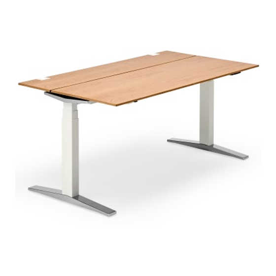
- Seite 1 TABLE.T/A/W Tischsystem Desk system Montageanleitung Assembly instructions...
-
Seite 3: Inhaltsverzeichnis
Inhalt Vorwort Montage von T- oder A-Fuß Manuelle Höhenverstellung Montage der Konsole Montage der Wange Montage und Bedienung der Schiebeplatte Abnehmen der Schiebeplatte bei Duoplattentischen Montage der Tischplatte (ohne Schiebefunktion) Bedienung der Tischklappe Elektrifizierung Komfortkabelführung mittels Kabelschlauch Montage der Klappwanne Montage der CPU-Halterung Montage der seitlichen Druckerablage Montage der Sichtrückwand... -
Seite 5: Vorwort
Vorwort Sehr geehrte Kundin, sehr geehrter Kunde! Sie haben sich für ein Markenprodukt aus dem Hause König + Neurath ent- schieden. Damit dieses Möbel zu Ihrer Zufriedenheit funktioniert, lesen Sie bitte diese Anweisungen vor Inbetriebnahme aufmerksam durch und beach- ten Sie die angegebenen Sicherheitshinweise. -
Seite 6: Montage Von T- Oder A-Fuß
Montageanleitung Tischsystem TABLE Diese Montageanleitung enthält alle nötigen Informationen zur Montage- und Umbauvorgängen für die Programmreihe „TABLE“. Die einzelnen Schritte sind, soweit erforderlich, gekennzeichnet und die un- terschiedlichen Schrauben und Schlüsselgrößen angegeben. Montage von T- oder A-Fuß Längstraversen (a) an T-Fuß (b) oder A-Fuß... -
Seite 7: Manuelle Höhenverstellung
Manuelle Höhen- verstellung T-Fuß Verstellung nach oben (a): Taste hoch schieben und ge- wünschte Höhe einstellen. Taste loslassen. Verstellung nach unten (b): Taste hoch schieben, Tisch- platte leicht anheben und nach unten drücken, Höhe einstellen und Taste loslassen. A-Fuß/T-Fuß Die unteren Stellschrauben (c) dienen zum Höhenaus- gleich bei Bodenunebenhei- ten. -
Seite 8: Montage Der Wange
Montage der Wange Längstraversen (a) an Wange (b) setzen und mit Zylinder- schrauben (c) M8x55 (SW6) von unten verschrauben. Tischplatte (d) auf Rahmen positionieren und von unten mit Holz-Flachkopfschrauben 5x13 durch Längstraversen und Konsolen befestigen. Die unteren Stellschrauben (e) dienen zum Höhenaus- gleich. -
Seite 9: Montage Und Bedienung Der Schiebeplatte
Montage und Be- dienung der Schiebe- platte Plattenbeschläge (a) auf- schieben. Platte (b) auf dem Tischrah- men positionieren, Plattenbeschläge an Konso- len zuschieben (c). Auslösegriff (d) nach unten ziehen, um Sicherungsras- tung der Schiebeplatte frei- zugeben. Griff rastet in geschlossener Position ein - Platte kann nur im geöffneten Zustand ab- genommen werden. -
Seite 10: Montage Der Tischplatte (Ohne Schiebefunktion)
Montage der Tisch- platte (ohne Schiebe- funktion) Platte auf Tischrahmen posi- tionieren und von unten mit Holz-Flachkopfschrauben 5x13 durch Längstraversen und Konsolen befestigen. Bedienung der Tischklappe (optional) Durch leichten Druck auf die vordere Oberfläche (a) lässt sich die Tischklappe öffnen (push to open-Funk- tion) und gibt so die Steckdo- se (b) frei. -
Seite 11: Elektrifizierung
Elektrifizierung Variante 1: Die Klammer (a) der Kabel- kette in die vorgesehene Öffnung der Kabelwanne einhängen. Variante 2: Abschlussteil (b) der Kabel- kette von unten an Tisch- platte schrauben und Klam- mer (c) in Kabelwanne einhängen. A-Fuß: Abdeckung (d) entfernen (beidseitig möglich), Kabel verlegen, Abdeckung wieder einsetzen (e). -
Seite 12: Komfortkabelführung Mittels Kabelschlauch
Komfortkabelfüh- rung mittels Kabel- schlauch Reißverschluss des Kabel- schlauchs öffnen, Kabel einlegen, Reißverschluss schließen (a). Seitliche Befestigung mittels Klettband: Hakenbandstrei- fen (b) an Fußrohr kleben, Kabel- schlauch ankletten. Kabelschlauch in Kabelwan- ne führen (c). -
Seite 13: Montage Der Klappwanne
Montage der Klappwanne Klappwannenhalter (a) an Längstraverse montieren, Pan-Head Schrauben ø5x60 verwenden. Klappwanne einhängen (b). Öffnen und schließen der Klappwanne wie unter (c) be- schrieben. öffnen schließen... -
Seite 14: Montage Der Cpu-Halterung
Montage der CPU- Halterung Winkel (a) mit Senkschrauben M6x8 (SW4) an Halteblech montieren. CPU-Halterung von unten mit selbstschneidenden Zylinder- schrauben M6x16 (SW5) an Quertraverse befestigen (b). Die CPU-Halterung kann wahlweise nach außen oder innen montiert werden. Bei Tischen mit Klappwanne nur außen! Montage der seit- lichen Druckerablage... -
Seite 15: Montage Der Sichtrückwand
Montage der Sichtrückwand Abdeckkappe (a) entfernen. Gewindeplatte (b) in Konsole einlegen. Den Rückwandhalter (c) von unten mittels Zylinderschrau- ben M6x16 (SW5) durch Konsole an innenliegender Gewindeplatte montieren. Sichtrückwand (d) an Rück- wandhalter mit Linsenschrau- ben M6x8 (SW4) befestigen. Abdeckkappe wieder in Kon- sole setzen (e). -
Seite 16: Montage Des Fly By-Paneels
Montage des Fly By-Paneels Abdeckstopfen (a) entfernen. Halteblech (b) des Fly By- Paneels in Konsole stecken und seitlich mit je 3 Zylinder- schrauben M6x10 (SW5) be- festigen (c). innen Montage des heraustrennen Tischpaneels (in Auf- bau- und Klemmadap- ter) Abdeckung (a) entfernen und Fenster freimachen. -
Seite 17: Montage Der Reling
Montage der Re- ling Abdeckung (a) entfernen. Relingprofil (b) mit Adapter (c) verschrauben, Zylinder- schrauben M6x20 (SW5) verwenden. Achtung: Vormontierte Adap- ter müssen demontiert wer- den. Abdeckkappe (d) entfernen. Nur bei 13er Adapter, zu- sätzliche Gegenplatte (e) in Konsole einlegen. Adapter mit Zylinderschrauben M6x10 (SW5) an Konsole montieren (f). -
Seite 18: Montage Der Seitl. Rundplatte Auf Duoplattentisch Ohne Schiebefuktion
Montage der seit- lichen Rundplatte auf Duoplattentisch ohne Schiebefunktion Zusatzriegel (a) und Distanz- platte (b) mit Euro-Schrau- ben 6,3x14 an Rundplatte be- festigen. Rundplatte auf Tischrahmen setzen, ausrichten (c) und von unten mit Holz-Flach- kopfschrauben durch Längs- traversen und Konsolen verschrauben (d). -
Seite 19: Montage Der Seitl. Rundplatte Auf Duoplattentisch Mit Schiebefuktion
Montage der seit- lichen Rundplatte auf Duoplattentisch mit Schiebefunktion Zusatzriegel (a) und Distanz- platte (b) mit Euro-Schrau- ben 6,3x14 an Rundplatte be- festigen. Rundplatte auf Tischrahmen setzen, ausrichten (c), Zu- satzriegel (d) und Distanzplat- te montieren. Platte mit Holz- Flachkopfschrauben durch vordere Längstraverse und Konsolen verschrauben (e). -
Seite 20: Montage Der Seitlichen Glasplatte Auf Duoplattentisch
Montage der seit- lichen Glasplatte auf Duoplattentisch Trägerplatte (a), wie unter Bild 19 oder 20 beschrieben, montieren. Elastikpuffer (b) von unten auf Glasplatte kleben. Glasplatte auf Trägerplatte po- sitionieren (c). Elastikpuffer Ansicht von unten... -
Seite 21: Montage Der Anbauelemente (Werkzeuglos)
Montage der An- bauelemente (werkzeuglos) Anbauelemente (a) werden in die Organisationsnut des Tischpaneels / Fly By-Pa- neels / Reling eingehängt. Aufsatz-Anbauelemente (b) werden von oben auf das Tischpaneel / Fly By-Paneel gesteckt. Belastbarkeitsangaben auf Seite 23 beachten! Zur Information: Die Ablage- schale kann in die Organi- sationsnut sowie in die Hal- terung eingehängt werden. -
Seite 22: Steckdosenbox, Zum Aufstecken Oder Anklemmen An Tischplatte
Steckdosenbox, heraustrennen zum Aufstecken oder Anklemmen an Tischplatte Abdeckung (a) entfernen und Fenster freimachen. Abdeckung auf Tischadapter setzen (b) und Steckdosen- box (c) in Tischadapter stecken, Gewindestift (SW3) (d) festziehen. Steckdosenzwinge (e) auf Tischplatte schieben. Von unten mittels Gewindestifte (SW4) festziehen (f). Steck- dosenbox auf Zwinge schie- ben und einklipsen (g). -
Seite 23: Technikcontainer, Montage Des Tischverbinders
Technikcontainer, Montage des Tisch- verbinders Abdeckung und Tischverbin- der (a) auf Technikcontainer setzen und von unten mit Zylinderschrauben M8x40 (SW6) und U-Scheiben be- festigen (b). Längstraversen des Tisch- rahmens, wie unter Bild 1 be- schrieben, montieren (ohne Abb.). Höhenausgleich des Tech- nikcontainers mittels unterer Stellschraube (c) im Möbel- fuß... -
Seite 24: Technikcontainer, Elektrifizierung
Technikcontainer, Elektrifizierung Tischverbinder: Abdeckung (a) aushängen, Kabel verlegen. Abdeckung wieder einhängen. Technikcontainer: Elektrifizierung mittels vor- montierter Kabelführungen (b) im Korpus möglich. -
Seite 25: Technikcontainer, Blendenjustierung
Technikcontainer, Blendenjustierung Abdeckkappen (a) entfernen. Höhenverstellung beidseitig durch hintere Schrauben (b). Seitenverstellung nur rechts durch vordere Schraube (c). Abdeckkappen wieder ein- klipsen (d). -
Seite 26: Sicherheitshinweise
Sicherheitshinweise Belastbarkeit der Anbauelemente: Ordnerablage einseitig Achtung: Maximale Belastbarkeit der Organisationsnut = 25 kg max. 10 kg Halterung mit Ordnerablage Ablageschale Ablageschale max. 10 kg max. 5 kg max. 5 kg/Ablageschale Monitorarm: Belastung max. 8 kg pro Monitorarm. Max. 3 Monitorarme pro Reling möglich! Max. - Seite 27 Sicherheitshinweise Bei Transport: Bitte den Tisch nicht an der Tischplatte heben oder tragen, sondern an dem Tischrahmen! Bei Umbaumaßnahmen Montageanleitung beachten! Bitte darauf achten, dass bei Elektrifizierung der Möbel, die Strom- kabel nicht eingeklemmt werden. Die Tische sind nicht für den Einsatz in Werkstatt oder Lagerbereich geeignet.
-
Seite 28: Pflege- Und Reinigungshinweise
Pflege- und Reinigungshinweise Kunststoff-, Metall- und Chromoberflächen : Oberfläche mit einem Staubtuch reinigen. Bei Verschmutzungen warmes Wasser verwenden und / oder einen milden Reiniger, danach trocken wischen. Achtung : Keine scheuernden Reinigungsmittel verwenden ! Diese können zu blei- benden, optischen Schäden führen. Chrom: Es sollten hier grundsätzlich keine alkohol-, chlor- oder säurehaltigen oder kratzenden Reiniger verwendet werden. - Seite 55 Deutschland König + Neurath AG Büromöbel-Systeme Industriestraße 1-3 61184 Karben Tel.: +49 (0)6039 483-0 Fax: +49 (0)6039 482-214 e-mail: info@koenig-neurath.de www.koenig-neurath.de Great Britain K + N International (Office Systems) Ltd 52 Britton Street London EC1M 5UQ Tel.: +44 (0)20 74909340 Fax: +44 (0)20 74909349 e-mail: info@koenig-neurath.co.uk www.koenig-neurath.co.uk...