Herunterladen Inhalt Inhalt Diese Seite drucken
Inhaltsverzeichnis

Werbung

Verfügbare Sprachen
  • DE

Verfügbare Sprachen

  • DEUTSCH, seite 75
ITALIANO
ULISSE COMPACT DELUX
EN
English - Instruction manual
IT
Italiano - Manuale di istruzioni
FR
Français - Manuel d'instructions
DE
Deutsch - Bedienungsanleitung
RU
Русский - Руководство по эксплуатации
Full HD PTZ camera with new DeLux technology for day/
night vision with exceptional night brightness

Werbung

Inhaltsverzeichnis

Fehlerbehebung

loading

Inhaltszusammenfassung für Videotec Ulisse Compact Delux

  • Seite 1 ITALIANO ULISSE COMPACT DELUX Full HD PTZ camera with new DeLux technology for day/ night vision with exceptional night brightness English - Instruction manual Italiano - Manuale di istruzioni Français - Manuel d’instructions Deutsch - Bedienungsanleitung Русский - Руководство по эксплуатации...
  • Seite 3 ENGLISH ULISSE COMPACT DELUX Full HD PTZ camera with new DeLux technology for day/ night vision with exceptional night brightness English - Instruction manual...
  • Seite 5: Inhaltsverzeichnis

    Contents E N G L I S H 1 About this manual ........................5 1.1 Typographical conventions ..............................5 2 Notes on copyright and information on trademarks ............. 5 3 Safety rules..........................5 4 Identification ..........................8 4.1 Product description and type designation ........................8 4.2 Product marking ..................................
  • Seite 6 10.4 Ceiling mounting ................................17 11 Instructions for normal operation ..................18 12 Maintenance .........................18 12.1 Fuses replacement ................................18 12.2 Factory Default ...................................18 13 Cleaning ..........................19 13.1 Cleaning the window and plastic parts ........................19 14 Information on disposal and recycling ................19 15 Troubleshooting ........................19 16 Technical data ........................20 16.1 General ....................................20 16.2 Mechanical ...................................20...
  • Seite 7: About This Manual

    1 About this manual 2 Notes on copyright and information on trademarks Read all the documentation supplied carefully before installing and using this unit. Keep the manual in a The mentioned names of products or companies are convenient place for future reference. trademarks or registered trademarks.
  • Seite 8 • The manufacturer declines all responsibility CAUTION! The white light LED illuminator for any damage caused by an improper use emits high-intensity visible light. In of the appliances mentioned in this manual. compliance with standard EN62471/ Furthermore, the manufacturer reserves the right IEC62471, the photobiological safety to modify its contents without any prior notice.
  • Seite 9 • This device was designed to be permanently • A power disconnect device must be included secured and connected on a building or on a in the electrical installation, and it must be very suitable structure. The device must be permanently quickly recognizable and operated if needed.
  • Seite 10: Identification

    ULISSE COMPACT DELUX is a Full HD network camera • Only skilled personnel should carry out featuring the new imaging and encoding technology maintenance on the device. When carrying out...
  • Seite 11: Product Marking

    4.2 Product marking 6 Preparing the product for The product has a label applied in compliance with CE marking. Any change that is not expressly approved by the manufacturer will invalidate the guarantee. 6.1 Safety precautions before use The appliance includes moving parts. Make sure that the unit is positioned where it is inaccessible under normal operating conditions.
  • Seite 12: Safely Disposing Of Packaging Material

    6.3 Contents 6.5 Preparatory work before installation Check the contents to make sure they correspond with the list of materials as below: 6.5.1 Mounting the bracket • Positioning unit Different types of supports are available (10 • Accessories box Accessories, page 17). Choose a suitable bracket for •...
  • Seite 13: Connection Of The Cables To The Base

    7 Installation 7.2 Fixing the base to the support Use the screws and the washers supplied Never, under any circumstances, make with the base. any changes or connections that are not shown in this handbook. Failure to follow After having positioned gasket (01), fasten base (02) the connection instructions that are given on support (03) using screws (04), toothed spring in the handbook may create serious safety...
  • Seite 14: Connection Of The Connector Board

    7.3 Connection of the connector 7.3.2 Connection of the power supply line board Electrical connections must be performed 7.3.1 Connector board description with the power supply disconnected and the circuit-breaker open. BOARD DESCRIPTION Connector Function When commencing installation make sure FUS1 Power line fuse that the specifications for the power supply...
  • Seite 15: Connection Of The Secondary Connector Board

    7.4 Connection of the secondary Connect the power supply cables to the J2 terminal as described in the table. connector board CONNECTION OF THE POWER SUPPLY LINE Colour Terminals All signal cables must be grouped together by means of a cable tie. Power supply 24Vac Defined by the installer N (Neutral)
  • Seite 16: Connection Of The Alarm Inputs

    7.4.2 Connection of the alarm inputs 7.4.3 Relays connection All signal cables must be grouped together The relay is usable with the specifications by means of a cable tie. described below. Working voltage: to 30Vac or 60Vdc. Current: 1A max. Use In case of free contact alarm make the connection as suitable cable sections with the following shown in the figure.
  • Seite 17: Connection Of The Ethernet Cable

    7.4.5 Connection of the Ethernet cable The side sets on the base and on the upper unit are thus aligned in the only possible position. Connect the J1 connector of the secondary connector board using a 5E category, or higher, UTP cable (7.4.1 Description of the secondary board, page 13).
  • Seite 18: Switching On

    On first access, the Home page will be displayed. For the configuration of the web interface, please refer to the instruction manual relating to the installed firmware version, available on the product web page on www.videotec.com. MNVCUCHDB_1905_EN...
  • Seite 19: Accessories

    10 Accessories 10.3 Parapet bracket Parapet bracket with internal cable channel. For further details on configuration and use, refer to the relative manual. 10.1 Washer The product can be equipped with an external pump that provides water to clean the glass. Fig.
  • Seite 20: Instructions For Normal Operation

    11 Instructions for normal 12.2 Factory Default operation It is possible to reset to the factory default settings. The effect of the Factory Default procedure is the Do not use the wiper if the outside same obtained through the web interface (Hard Reset temperature is below 0°C or in case of ice.
  • Seite 21: Cleaning

    14 Information on disposal • Restore the DIP 3 as shown in the figure. and recycling The European Directive 2012/19/EU on Waste Electrical and Electronic Equipment (WEEE) mandates DIP3 DIP2 that these devices should not be disposed of in the normal flow of municipal solid waste, but they should be collected separately in order to optimize the recovery stream and recycling of the materials that...
  • Seite 22: Technical Data

    16 Technical data Power consumption: • 40W, P&T static, heating switched off CAUTION! TNV-1 installation type. The • 60W, P&T in motion, heating switched off installation is type TNV-1, do not connect it • 125W, peak at start-up, heating switched on to SELV circuits.
  • Seite 23: I/O Interface

    16.6 I/O interface 16.8 Illuminators I/O alarm board LED illuminator • Alarm inputs: 1 Horizontal beam: 10° or 30° • Relay outputs: 1 (1A, 30Vac/60Vdc max) Wavelength: 850nm, 940nm, white light Automatic and remote switching on 16.7 Cameras 16.9 Environment Day/Night Full HD 30x Resolution: Full HD 1080p (1920x1080pixel) For installation indoors and outdoors...
  • Seite 24: Technical Drawings

    17 Technical drawings The indicated measurements are expressed in millimetres. Fig. 25 ULISSE COMPACT DELUX. MNVCUCHDB_1905_EN...
  • Seite 25 Fig. 26 ULISSE COMPACT DELUX with LED illuminator. MNVCUCHDB_1905_EN...
  • Seite 26 Email: info@videotec.com Tel. +33 1 60491816 - Fax +33 1 69284736 Email: info.fr@videotec.com Asia Pacific Videotec (HK) Ltd Americas Videotec Security, Inc. Flat 8, 19/F. On Dak Industrial Building, No. 2-6 Wah Sing Street Gateway Industrial Park, 35 Gateway Drive, Suite 100 Kwai Chung, New Territories - Hong Kong Plattsburgh, NY 12901 - U.S.A.
  • Seite 27 ITALIANO ULISSE COMPACT DELUX Telecamera PTZ Full HD con nuova tecnologia DELUX, visione day/night con straordinaria luminosità notturna Italiano - Manuale di istruzioni...
  • Seite 29 Sommario I T A L I A N O 1 Informazioni sul presente manuale ..................5 1.1 Convenzioni tipografiche ..............................5 2 Note sul copyright e informazioni sui marchi commerciali ........... 5 3 Norme di sicurezza ........................5 4 Identificazione .......................... 8 4.1 Descrizione e designazione del prodotto ........................
  • Seite 30 10.4 Fissaggio a soffitto ................................17 11 Istruzioni di funzionamento ordinario ................18 12 Manutenzione ........................18 12.1 Sostituzione dei fusibili ..............................18 12.2 Factory Default ...................................18 13 Pulizia ............................19 13.1 Pulizia della finestra e delle parti in plastica ......................19 14 Informazioni sullo smaltimento e il riciclo .................19 15 Risoluzione dei problemi .....................19 16 Dati tecnici ..........................20 16.1 Generale ....................................20...
  • Seite 31: Informazioni Sul Presente Manuale

    1 Informazioni sul presente 2 Note sul copyright e manuale informazioni sui marchi commerciali Prima di installare e utilizzare questa unità, leggere attentamente tutta la documentazione fornita. Tenere I nomi di prodotto o di aziende citati sono marchi il manuale a portata di mano per consultazioni commerciali o marchi commerciali registrati successive.
  • Seite 32 • Il produttore declina ogni responsabilità per ATTENZIONE! L’illuminatore a LED a luce eventuali danni derivanti da un uso improprio bianca emette luce ad alta intensità visibile. delle apparecchiature menzionate in questo La valutazione foto-biologica di sicurezza, manuale. Si riserva inoltre il diritto di modificarne il in accordo con la norma EN62471/ contenuto senza preavviso.
  • Seite 33 • Questo dispositivo è stato progettato per essere • L’impianto elettrico deve essere dotato di un fissato e collegato in maniera permanente sezionatore di rete prontamente riconoscibile e su un edificio o su una struttura adeguata. Il utilizzabile in caso di necessità. dispositivo deve essere fissato e collegato in •...
  • Seite 34: Identificazione

    ULISSE COMPACT DELUX è una telecamera PTZ Full • La manutenzione del dispositivo deve essere HD di rete che integra la nuova tecnologia di imaging eseguita solo da personale qualificato. Durante le e encoding per la videosorveglianza in esterno operazioni di manutenzione l'operatore è...
  • Seite 35: Marcatura Del Prodotto

    4.2 Marcatura del prodotto 6 Preparazione del prodotto per l'utilizzo Sul prodotto è applicata una etichetta conforme alla marcatura CE. Qualsiasi intervento non espressamente approvato dal costruttore fa decadere la garanzia. 6.1 Precauzioni di sicurezza prima dell'utilizzo L'apparecchiatura comprende parti mobili. Assicurarsi che l'unità...
  • Seite 36: Smaltimento In Sicurezza Dei Materiali Di Imballaggio

    6.3 Contenuto 6.5 Lavoro preparatorio prima dell’installazione Controllare che il contenuto sia corrispondente alla lista del materiale sotto elencato: 6.5.1 Fissaggio del supporto • Unità di posizionamento Sono disponibili diversi tipi di supporto (10 • Scatola accessori Accessori, pagina 17). Scegliere il supporto adeguato •...
  • Seite 37: Installazione

    7 Installazione 7.2 Fissaggio della base al supporto Non effettuare per nessun motivo alterazioni o collegamenti non previsti Utilizzare le viti e le rondelle fornite con la in questo manuale. Il mancato rispetto base. delle indicazioni fornite nel manuale in merito ai collegamenti può...
  • Seite 38: Collegamento Della Scheda Connettori

    7.3 Collegamento della scheda 7.3.2 Collegamento della linea di alimentazione connettori Eseguire le connessioni elettriche in 7.3.1 Descrizione della scheda assenza di alimentazione e con dispositivo connettori di sezionamento aperto. DESCRIZIONE DELLA SCHEDA All’atto dell’installazione controllare che Connettore Funzione le caratteristiche di alimentazione fornite FUS1 Fusibile della linea di alimentazione dall’impianto corrispondano a quelle...
  • Seite 39: Collegamento Della Scheda Connettori Secondaria

    7.4 Collegamento della scheda Collegare i cavi di alimentazione al morsetto J2 come descritto in tabella. connettori secondaria COLLEGAMENTO DELLA LINEA DI ALIMENTAZIONE Colore Morsetti Tutti i cavi di segnale devono essere raggruppati con una fascetta. Alimentazione 24Vac Definito dall'installatore N (Neutro) 7.4.1 Descrizione della scheda Definito dall'installatore...
  • Seite 40: Collegamento Degli Ingressi Di Allarme

    7.4.2 Collegamento degli ingressi di 7.4.3 Collegamento dei relè allarme Il relè è utilizzabile con le specifiche descritte di seguito. Tensione di lavoro: Tutti i cavi di segnale devono essere fino a 30Vac oppure 60Vdc. Corrente: 1A raggruppati con una fascetta. max.
  • Seite 41: Collegamento Del Cavo Di Rete Ethernet

    7.4.5 Collegamento del cavo di rete In questo modo le sporgenze laterali sulla base e sull'unità superiore sono allineate nell’unica Ethernet posizione possibile. Collegare il connettore J1 della scheda connettori secondaria tramite un cavo UTP di categoria 5E o superiore (7.4.1 Descrizione della scheda secondaria, pagina 13).
  • Seite 42: Accensione

    Al primo accesso sarà visualizzata la pagina di Home. Per la configurazione dell'interfaccia web consultare il manuale relativo alla versione firmware installata, disponibile nella pagina web del prodotto sul nostro sito www.videotec.com. MNVCUCHDB_1905_IT...
  • Seite 43: Accessori

    10 Accessori 10.3 Supporto da parapetto Supporto per montaggio a parapetto con passaggio Per ulteriori dettagli sulla configurazione interno cavi. e l’utilizzo fare riferimento al manuale del relativo accessorio. 10.1 Impianto di lavaggio Il prodotto può essere dotato di una pompa esterna che fornisce acqua per la pulizia del vetro.
  • Seite 44: Istruzioni Di Funzionamento Ordinario

    11 Istruzioni di 12.2 Factory Default funzionamento ordinario È possibile effettuare il ripristino delle impostazioni di fabbrica. Non utilizzare il tergicristallo se la Il risultato della procedura di Factory Default è lo temperatura esterna è inferiore a 0°C o in stesso ottenuto tramite interfaccia web (pulsante presenza di ghiaccio.
  • Seite 45: Pulizia

    14 Informazioni sullo • Ripristinare il DIP 3 come illustrato in figura. smaltimento e il riciclo La Direttiva Europea 2012/19/UE sui Rifiuti di Apparecchiature Elettriche ed Elettroniche (RAEE) DIP3 DIP2 prevede che questi apparecchi non debbano essere smaltiti nel normale flusso dei rifiuti solidi urbani, ma che vengano raccolti separatamente per ottimizzare il flusso di recupero e riciclaggio dei materiali che DIP1...
  • Seite 46: Dati Tecnici

    16 Dati tecnici Potenza assorbita: • 40W, brandeggio fermo, riscaldamento spento ATTENZIONE! L'installazione è di tipo TNV-1. • 60W, brandeggio in movimento, riscaldamento Non collegare a circuiti SELV. spento • 125W, picco all’accensione, riscaldamento acceso ATTENZIONE! Per ridurre il rischio di Potenza assorbita con illuminatore acceso: incendio usare solamente cavi certificati UL Listed o CSA aventi sezioni maggiori o...
  • Seite 47: Interfaccia I/O

    16.6 Interfaccia I/O 16.8 Illuminatori Scheda allarme I/O Illuminatore a LED • Ingressi allarme: 1 Fascio orizzontale: 10° oppure 30° • Uscite relè: 1 (1A, 30Vac/60Vdc max) Lunghezza d’onda: 850nm, 940nm, luce bianca Accensione automatica e da remoto 16.7 Telecamere 16.9 Ambiente Day/Night Full HD 30x Risoluzione: Full HD 1080p (1920x1080pixel)
  • Seite 48: Disegni Tecnici

    17 Disegni tecnici Le misure indicate sono espresse in millimetri. Fig. 25 ULISSE COMPACT DELUX. MNVCUCHDB_1905_IT...
  • Seite 49 Fig. 26 ULISSE COMPACT DELUX con illuminatore a LED. MNVCUCHDB_1905_IT...
  • Seite 50 Email: info@videotec.com Tel. +33 1 60491816 - Fax +33 1 69284736 Email: info.fr@videotec.com Asia Pacific Videotec (HK) Ltd Americas Videotec Security, Inc. Flat 8, 19/F. On Dak Industrial Building, No. 2-6 Wah Sing Street Gateway Industrial Park, 35 Gateway Drive, Suite 100 Kwai Chung, New Territories - Hong Kong Plattsburgh, NY 12901 - U.S.A.
  • Seite 51 FRANÇAIS ULISSE COMPACT DELUX Caméra PTZ Full HD avec la nouvelle technologie DELUX pour une vision jour/nuit avec une extraordinaire luminosité nocturne Français - Manuel d’instructions...
  • Seite 53 Sommaire F R A N Ç A I S 1 À propos de ce mode d’emploi ....................5 1.1 Conventions typographiques ............................5 2 Notes sur le copyright et informations sur les marques de commerce ........ 5 3 Normes de securité ........................5 4 Identification ..........................
  • Seite 54 10.4 Fixation au plafond ................................17 11 Instructions de fonctionnement courant ................18 12 Entretien ..........................18 12.1 Remplacement des fusibles ............................18 12.2 Factory Default ...................................18 13 Nettoyage..........................19 13.1 Nettoyage de la fenêtre et des parties en plastique .....................19 14 Informations sur l'élimination et le recyclage ..............19 15 Dépannage ..........................19 16 Données techniques ......................20 16.1 Généralités ...................................20...
  • Seite 55: Propos De Ce Mode D'emploi

    1 À propos de ce mode 2 Notes sur le copyright d’emploi et informations sur les marques de commerce Avant d'installer et d'utiliser cette unité, lire attentivement toute la documentation fournie. Les noms de produit ou de sociétés cités sont des Garder le manuel à...
  • Seite 56 • Le fabricant décline toute responsabilité pour les ATTENTION! Le projecteur à LED à lumière dommages éventuels dus à une utilisation non blanche émet de la lumière à haute appropriée des appareils mentionnés dans ce intensité visible. L'évaluation photo- manuel. On réserve en outre le droit d’en modifier biologique de sécurité, conformément à...
  • Seite 57 • Cet appareil est conçu pour être fixé et relié de • L'installation électrique doit être équipée d'un manière permanente sur un bâtiment ou une sectionneur de réseau facile à reconnaître et à structure adéquate. L'appareil doit être fixé et relié utiliser en cas de nécessité.
  • Seite 58: Identification

    H.264 / AVC, MPEG4, MJPEG ou JPEG et jusqu'à un maximum de 3 flux vidéo Full HD simultanés et indépendants. ULISSE COMPACT DELUX est la solution idéale pour la vidéosurveillance des zones urbaines et industrielles, des infrastructures critiques, des transports, des périmètres et des lignes de frontières.
  • Seite 59: Marquage Du Produit

    4.2 Marquage du produit 6 Préparation du produit en vue de l’utilisation Une étiquette conforme au marquage CE est apposée sur le produit. Toute modification non approuvée expressément par le fabricant entraînera l’annulation de la garantie. 6.1 Précautions de sécurité avant l’utilisation L'appareil comprend des parties mobiles.
  • Seite 60: Élimination Sans Danger Des Matériaux D'emballage

    6.3 Contenu 6.5 Opérations à effectuer avant l’installation Contrôler que le contenu correspond à la liste matériel indiquée ci-dessous: 6.5.1 Fixation du support • Unité de positionnement Plusieurs types de supports sont disponibles (10 • Emballage accessoires Accessoires, page 17). Choisir le support convenable •...
  • Seite 61: Installation

    7 Installation 7.2 Fixage de la base au support Utiliser les vis et les rondelles fournies avec Ne procéder sous aucun prétexte à des la base. modifications ou des connexions non prévues dans ce manuel. L’utilisation Après avoir installé la garniture (01), fixer la base d’appareils inadéquats peut comporter (02) sur son support (03) au moyen des vis (04), des des risques sérieux pour les appareils et la...
  • Seite 62: Connexion De La Carte De Connexion

    7.3 Connexion de la carte de 7.3.2 Connexion de la ligne d'alimentation connexion Il faut effectuer les connexions électriques 7.3.1 Description de la carte de en absence d'alimentation et lorsque le connexion dispositif de sectionnement ouvert. DESCRIPTION DE LA CARTE Contrôler que les sources d'alimentation et Connecteur Fonction...
  • Seite 63: Connexion De La Carte Secondaire Des Connecteurs

    7.4 Connexion de la carte Connecter les câbles d'alimentation au borne J2 comme décrit dans le tableau. secondaire des connecteurs CONNEXION DE LA LIGNE D'ALIMENTATION Couleur Bornes Tous les câbles de signalisation doivent également être regroupés avec un collier. Alimentation 24Vac Défini par l'installateur N (Neutre) 7.4.1 Description de la carte secondaire...
  • Seite 64: Connexion Des Entrées De L'alarme

    7.4.2 Connexion des entrées de l'alarme 7.4.3 Branchement des relais Tous les câbles de signalisation doivent Le relais est utilisable avec les spécifications également être regroupés avec un collier. décrites ci-après. Tension de travail: jusqu'à 30Vac ou 60Vdc. Courant: 1A max. Utiliser Dans le cas d'une alarme à...
  • Seite 65: Branchement Du Câble De Réseau Ethernet

    7.4.5 Branchement du câble de réseau Les saillies latérales sur la base et sur l’unité supérieure sont ainsi alignées dans la seule position Ethernet possible. Connecter le connecteur J1 à la carte secondaire des connecteurs à l'aide d'un câble UTP de catégorie 5E ou de catégorie supérieure (7.4.1 Description de la carte secondaire, page 13).
  • Seite 66: Allumage

    à l’adresse : http:// indirizzo_ip. La page d'accueil sera affichée au premier accès. Pour la configuration de l'interface web, veuillez vous reporter au manuel d’instruction relatif à la version du firmware installé, disponible sur la page web du produit sur www.videotec.com. MNVCUCHDB_1905_FR...
  • Seite 67: Accessoires

    10 Accessoires 10.3 Support fixation sol Support de fixation au sol avec passage interne des Pour de plus amples informations sur la câbles. configuration et l'utilisation, consulter le manuel de l'accessoire correspondant. 10.1 Système de lavage Le produit peut être équipé d'une pompe externe qui fournit l'eau pour nettoyer la vitre.
  • Seite 68: Instructions De Fonctionnement Courant

    11 Instructions de 12.2 Factory Default fonctionnement courant Il est possible d'effectuer le rétablissement des programmations d'usine. Ne pas utiliser l’essuie-glace avec Le résultat de la procédure de Standard d'usine est le température extérieure inférieure à 0°C ou mème que celui obtenu par interface web (bouton en cas de givre.
  • Seite 69: Nettoyage

    14 Informations sur • Rétablir le DIP 3 comme sur la figure. l'élimination et le recyclage La Directive Européenne 2012/19/UE sur les déchets d'équipements électriques et électroniques (DEEE) DIP3 DIP2 exige que ces dispositifs ne doivent pas être éliminés dans le flux normal de déchets solides municipaux, mais ils doivent être collectés séparément afin d'optimiser le flux de récupération et de recyclage DIP1...
  • Seite 70: Données Techniques

    16 Données techniques Puissance absorbée: • 40W, tourelle à l’arrêt, chauffage éteint ATTENTION! L'installation est du type TNV- • 60W, tourelle en mouvement, chauffage éteint 1. Ne pas la connecter à des circuits SELV. • 125W, pic à l’allumage, chauffage allumé Puissance absorbée avec projecteur allumé: ATTENTION! Pour réduire les risques d’incendie, utiliser uniquement des câbles...
  • Seite 71: Interface I/O

    16.6 Interface I/O 16.8 Projecteurs I/O carte d’alarme Projecteur à LED • Entrées d'alarme: 1 Angle horizontal: 10° ou 30° • Sorties relais: 1 (1A, 30Vac/60Vdc max) Longueur d'onde: 850nm, 940nm, lumière blanche Allumage automatique et à distance 16.7 Caméras 16.9 Environnement Day/Night Full HD 30x Résolution: Full HD 1080p (1920x1080pixel)
  • Seite 72: Dessins Techniques

    17 Dessins techniques Les tailles indiquées sont en millimètres. Fig. 25 ULISSE COMPACT DELUX. MNVCUCHDB_1905_FR...
  • Seite 73 Fig. 26 ULISSE COMPACT DELUX avec projecteur à LED. MNVCUCHDB_1905_FR...
  • Seite 74 Email: info@videotec.com Tel. +33 1 60491816 - Fax +33 1 69284736 Email: info.fr@videotec.com Asia Pacific Videotec (HK) Ltd Americas Videotec Security, Inc. Flat 8, 19/F. On Dak Industrial Building, No. 2-6 Wah Sing Street Gateway Industrial Park, 35 Gateway Drive, Suite 100 Kwai Chung, New Territories - Hong Kong Plattsburgh, NY 12901 - U.S.A.
  • Seite 75 DEUTSCH ULISSE COMPACT DELUX Full HD PTZ-Kamera mit der neuen DELUX-Technologie für Tag- Nacht-Aufnahmen mit erstaunlicher Helligkeit bei Dunkelheit Deutsch - Bedienungsanleitung...
  • Seite 77 Inhaltsverzeichnis D E U T S C H 1 Allgemeines ..........................5 1.1 Schreibweisen..................................5 2 Anmerkungen zum Copyright und Informationen zu den Handelsmarken ......5 3 Sicherheitsnormen ........................5 4 Identifizierung .......................... 8 4.1 Beschreibung und Bezeichnung des Produktes ......................8 4.2 Kennzeichnung des Produkts ............................
  • Seite 78 10.4 Deckenbefestigung ................................17 11 Anleitung für den normalen Betrieb ..................18 12 Wartung ..........................18 12.1 Wechsel der Sicherungen ...............................18 12.2 Factory Default ...................................18 13 Reinigung ..........................19 13.1 Reinigung des Fensters und der Kunststoffteile .....................19 14 Informationen bezüglich Entsorgung und Recycling ............19 15 Problemlösung ........................19 16 Technische Daten ........................20 16.1 Allgemeines ..................................20...
  • Seite 79: Allgemeines

    1 Allgemeines 2 Anmerkungen zum Copyright und Vor Installation und Anwendung der Einheit ist die gesamte gelieferte Dokumentation aufmerksam zu Informationen zu den lesen. Zum späteren Nachschlagen das Handbuch in Reichweite aufbewahren. Handelsmarken 1.1 Schreibweisen Die angeführten Produkt- oder Firmennamen sind Handelsmarken oder eingetragene Handelsmarken.
  • Seite 80 • Der Hersteller lehnt jede Haftung für eventuelle ACHTUNG! Der Weißlicht-LED- Schäden ab, die aufgrund unsachgemäßer Schweinwerfer emittiert sichtbares Anwendung der in diesem Handbuch erwähnten Licht mit hoher Intensität. Aufgrund Geräte entstanden ist. Ferner behält er sich der Bewertung der photobiologischen das Recht vor, den Inhalt ohne Vorkündigung Sicherheit, in Übereinstimmung mit der abzuändern.
  • Seite 81 • Die Einrichtung ist für die dauerhafte Befestigung • Die elektrische Anlage muss mit einem und Verbindung in ein Gebäude oder eine andere Netztrennschalter versehen sein, der im Bedarfsfall geeignete Struktur konzipiert. Vor jeder Operation sofort erkannt und gebraucht werden kann. muss die Einrichtung dauerhaft befestigt und •...
  • Seite 82: Identifizierung

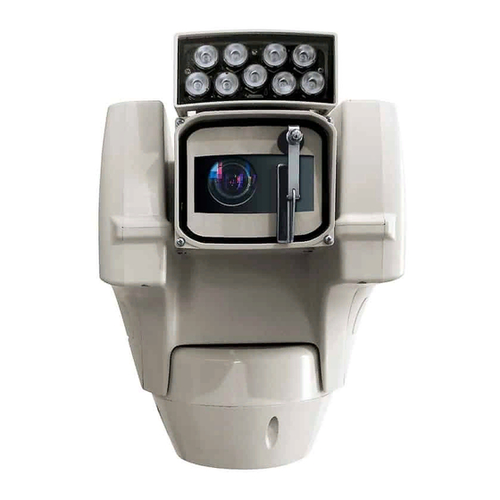
    Die Videobilder werden über das Netzwerk mit Kompression H.264 / AVC, MPEG4, MJPEG oder JPEG und bis zu max.3 gleichzeitige und unabhängige Full HD Videostreams gesendet. ULISSE COMPACT DELUX ist die ideale Lösung für Sicherheitsanwendungen von Stadt- und Industriegebieten, kritischen Infrastrukturen, Transporten, umlaufenden Sperranlagen und Grenzlinien.
  • Seite 83: Kennzeichnung Des Produkts

    4.2 Kennzeichnung des Produkts 6 Vorbereitung des Produktes auf den Gebrauch Auf dem Produkt befindet sich ein Etikett, das mit der CE-Kennzeichnung Jede vom Hersteller nicht ausdrücklich übereinstimmt. genehmigte Veränderung führt zum Verfall der Gewährleistungsrechte. 6.1 Sicherheitsvorkehrungen vor dem Gebrauch Das Gerät umfasst bewegliche Teile.
  • Seite 84: Sichere Entsorgung Der Verpackungsmaterialien

    6.3 Inhalt 6.5 Auf die Installation vorbereitende Tätigkeiten Prüfen Sie, ob der Inhalt mit der nachstehenden Materialliste übereinstimmt: 6.5.1 Befestigung der Halterung • Positionierungseinheit Verschiedene Halterungen sind (10 Zubehör, Seite • Zubehör Schachtel 17). Das geeignetste für die Installation auswählen •...
  • Seite 85: Installation

    7 Installation 7.2 Befestigung der Basis an der Halterung Unter keinen Umständen dürfen Veränderungen oder Anschlüsse Verwenden Sie die mit der Basis gelieferten vorgenommen werden, die in diesem Schrauben und Unterlegscheiben. Handbuch nicht genannt sind. Die Missachtung der Angaben, die das Nach der Positionierung der Dichtung (01) muss Handbuch zu den Anschlüssen macht, die Basis (02) auf der Halterung (03) befestigt...
  • Seite 86: Anschluss Der Verbinderplatine

    7.3 Anschluss der 7.3.2 Anschluss der Stromversorgung Verbinderplatine Die elektrischen Anschlüsse nur durchführen, wenn die Stromversorgung 7.3.1 Beschreibung der Karte abgetrennt und die Trennvorrichtung offen Anschlüsse ist. BESCHREIBUNG DER PLATINE Im Zuge der Installation ist zu prüfen, Verbinder Funktion ob die Merkmale der von der Anlage bereitgestellten Versorgung mit den FUS1 Schmelzsicherung der Versorgungsleitung...
  • Seite 87: Anschluss Der Sekundären Steckerkarte

    7.4 Anschluss der sekundären Die Versorgungskabel sind der J2 Klemme nach der Tabelle anzuschließen. Steckerkarte ANSCHLUSS DER STROMVERSORGUNG Farbe Klemmen Alle Signalkabel mit einem Kabelbinder müssen zusammengefasst werden. Netzteil 24Vac Vom Installateur festgelegt. N (Nullleiter) 7.4.1 Beschreibung der sekundären Vom Installateur festgelegt. L (Phase) Karte Gelb/Grün...
  • Seite 88: Anschluss Der Alarmeingänge

    7.4.2 Anschluss der Alarmeingänge 7.4.3 Anschluss der Relais Alle Signalkabel mit einem Kabelbinder Es kann das Relais mit den in Folge müssen zusammengefasst werden. beschriebenen Spezifikationen verwendet werden. Arbeitsspannung: bis zu 30Vac Im Falle von Alarm mit potentialfreiem Kontakt muss oder 60Vdc.
  • Seite 89: Anschluss Des Ethernet-Kabels

    7.4.5 Anschluss des Ethernet-Kabels Auf diese Weise sind die seitlichen Überstände auf der Basis und der oberen Einheit in der einzig Stecker J1 der sekundären Steckerkarte mit einem möglichen Position ausgerichtet. UTP Kabel anschließen, das mindestens zu der Kategorie 5E gehört. (7.4.1 Beschreibung der sekundären Karte, Seite 13).
  • Seite 90: Einschaltung

    Browser mit der Adresse http://indirizzo_ip herzustellen. Beim ersten Zugriff wird die Startseite angezeigt. Informationen zur Konfiguration der Webschnittstelle finden Sie im Handbuch, das sich auf die installierte Firmware-Version bezieht. Das Handbuch ist auf der Produktwebseite in www.videotec.com verfügbar. MNVCUCHDB_1905_DE...
  • Seite 91: Zubehör

    10 Zubehör 10.3 Halterung für Brüstungsmontage Für weitere Details zur Konfiguration und zum Gebrauch beachten Sie bitte das Brüstunghalterung mit interner Kabelführung. Handbuch des entsprechenden Geräts. 10.1 Waschanlage Das Produkt kann mit einer externen Pumpe ausgestattet werden, die Wasser für die Reinigung des Glases liefert.
  • Seite 92: Anleitung Für Den Normalen Betrieb

    11 Anleitung für den 12.2 Factory Default normalen Betrieb Die werkseitigen Anfangseinstellungen lassen sich wiederherstellen. Der Scheibenwischer ist bei Das Ergebnis der Factory-Default-Prozedur entspricht Aussentemperaturen unter 0°C oder bei dem über die Webschnittstelle erhaltenem Ergebnis Frost nicht zu betätigen. (Hard-Resetknopf, Web Interface Bedienungs- anleitungen, Werkzeuge Seite).
  • Seite 93: Reinigung

    14 Informationen bezüglich • DIP 3 wiederherstellen, siehe Abbildung. Entsorgung und Recycling Die EU-Richtlinie 2012/19/ЕU über Elektro- und Elektronik- Altgeräte (WEEE) verpflichtet, dass diese Geräte nicht DIP3 DIP2 zusammenn mit festen Haushaltsabfällen entsorgt werden sollten. Diese besonderen Abfällen müssen separat gesammelt werden, um den Rückgewinnungsstrom und das Recycling der darin enthaltenen Materialien zu DIP1...
  • Seite 94: Technische Daten

    16 Technische Daten Leistungsaufnahme: • 40W, S-N-Kopf unbewegt, ohne Heizung ACHTUNG! Die Anlage gehört zum Typ TNV- • 60W, S-N-Kopf in Bewegung, ohne Heizung 1. Nicht an Kreisläufe SELV anschließen. • 125W, Spitzenverbrauch, laufende Heizung Leistungsaufnahme mit Scheinwerfer auf: ACHTUNG! Zur Senkung der Brandgefahr dürfen nur UL Listed oder CSA zertifizierte •...
  • Seite 95: I/O-Schnittstelle

    16.6 I/O-Schnittstelle 16.8 Scheinwerfer I/O Alarm-Karte LED- Scheinwerfer • Alarmeingänge: 1 Horizontaler Winkel: 10° oder 30° • Relais-Ausgänge: 1 (1A, 30Vac/60Vdc max) Wellenlänge: 850nm, 940nm, Weißlicht Automatische und Ferneinschaltung 16.7 Kamera 16.9 Umgebung Day/Night Full HD 30x Auflösung: Full HD 1080p (1920x1080pixel) Montage für den Innen- und Außenbereich Image Sensor: 1/2.8"...
  • Seite 96: Technische Zeichnungen

    17 Technische Zeichnungen Die Maße sind in Millimetern angegeben. Abb. 25 ULISSE COMPACT DELUX. MNVCUCHDB_1905_DE...
  • Seite 97 Abb. 26 ULISSE COMPACT DELUX mit LED Scheinwerfer. MNVCUCHDB_1905_DE...
  • Seite 98 Email: info@videotec.com Tel. +33 1 60491816 - Fax +33 1 69284736 Email: info.fr@videotec.com Asia Pacific Videotec (HK) Ltd Americas Videotec Security, Inc. Flat 8, 19/F. On Dak Industrial Building, No. 2-6 Wah Sing Street Gateway Industrial Park, 35 Gateway Drive, Suite 100 Kwai Chung, New Territories - Hong Kong Plattsburgh, NY 12901 - U.S.A.
  • Seite 99 РУССКИЙ ULISSE COMPACT DELUX PTZ-камера с разрешением Full HD с новой технологией DeLux для работы в режиме день/ночь с необычайно ярким изображением Русский - Руководство по эксплуатации...
  • Seite 101 Комплект оборудования Р У С С К И Й 1 О настоящем руководстве ..................... 5 1.1 Типографские условные обозначения ........................5 2 Примечания в отношении авторского права и информация о торговых марках..5 3 Правила техники безопасности ................... 5 4 Обозначение ..........................8 4.1 Описание...
  • Seite 102 10.4 Крепление на потолок ..............................17 11 Инструкции по работе в нормальном режиме ..............18 12 Техническое обслуживание ....................18 12.1 Замена предохранителей .............................18 12.2 Factory Default ...................................18 13 Очистка ..........................19 13.1 Чистка окна и пластмассовых деталей ........................19 14 Информация об утилизации и переработке ..............19 15 Поиск...
  • Seite 103: О Настоящем Руководстве

    1 О настоящем 2 Примечания в руководстве отношении авторского права и информация о Внимательно ознакомьтесь со всей документацией, входящей в комплект поставки, торговых марках перед тем как приступить к установке и эксплуатации данного оборудования. Всегда Названия устройств или компаний, упоминаемые держите...
  • Seite 104 • Производитель не несет ответственности за ПРЕДУПРЕЖДЕНИЕ! Светодиодный любые повреждения, возникающие в результате осветитель белого света испускает неправильного использования указанного видимый свет высокой интенсивности. в настоящем руководстве оборудования. В соответствии с оценкой Помимо этого, производитель сохраняет фотобиологической безопасности в за собой право изменять содержание рамках...
  • Seite 105 • Это устройство разработано для подключения • Электрическая система оснащается и установки на здании или подходящей выключателем питания, который можно легко конструкции на постоянной основе. Устройство найти и использовать в случае необходимости. следует надежно закрепить и подключить перед • Отдельная защитная заземляющая клемма выполнением...
  • Seite 106: Обозначение

    отключении источника питания и отсоединении типа устройства кабелей, ведущих к другим устройствам. • Только опытные сотрудники должны проводить ULISSE COMPACT DELUX является сетевой камерой с техническое обслуживание устройства. При разрешением Full HD с новой технологией передачи проведении технического обслуживания и кодирования изображения для наружного...
  • Seite 107: Маркировка Изделия

    4.2 Маркировка изделия 6 Подготовка устройства к использованию На устройстве размещается этикетка в соответствии с маркировкой CE. Любое изменение, которое выполняется без разрешения, явным образом предоставленного производителем, аннулирует гарантию. 6.1 Меры безопасности, предпринимаемые перед началом эксплуатации Рис. 2 Оборудование включает движущиеся детали.
  • Seite 108: Комплект Оборудования

    6.3 Комплект оборудования 6.5 Подготовительные работы перед установкой Проверьте комплект оборудования на соответствие представленному ниже списку 6.5.1 Установка кронштейна материалов: Доступны различные виды опорных конструкций • Устройство позиционирования (10 Комплектующие, страница 17). Выберите • Коробка с комплектующими подходящий кронштейн для установки и •...
  • Seite 109: Монтаж

    7 Монтаж 7.2 Крепление основания к опорной конструкции Никогда и ни при каких обстоятельствах не выполняйте изменений или Используйте винты и шайбы, подключений, не предусмотренных поставляемые вместе с основанием. настоящим руководством. Несоблюдение изложенных в руководстве инструкций После установки уплотнителя (01) закрепите по...
  • Seite 110: Подключение Платы Разъемов

    7.3 Подключение платы 7.3.2 Подключение линии питания разъемов Выполнять электрические подключения необходимо при отключенном источнике 7.3.1 Описание платы разъемов питания и разомкнутом выключателе сети. ОПИСАНИЕ ПЛАТЫ Разъем Функция Перед началом монтажа убедитесь в FUS1 Предохранитель линии питания том, что характеристики источника FUS2 Предохранитель...
  • Seite 111: Подключение Вторичной Платы Подключения

    7.4 Подключение вторичной Подключите кабели питания к клемме J12, как указано в таблице. платы подключения ПОДКЛЮЧЕНИЕ ЛИНИИ ПИТАНИЯ Цвет Клеммы Все сигнальные кабели необходимо собрать в пучок с помощью кабельной Источник питания 24Vac стяжки. Определяется установщиком N (Нейтраль) Определяется установщиком L (Фаза) 7.4.1 Описание...
  • Seite 112: Подключение Входов Сигнала Тревоги

    7.4.2 Подключение входов сигнала 7.4.3 Подключение реле тревоги Используйте реле с указанными ниже характеристиками. Рабочее напряжение: Все сигнальные кабели необходимо до 30Vac или 60Vdc. Сила тока: 1A max. собрать в пучок с помощью кабельной Используйте кабели соответствующего стяжки. сечения со следующими В...
  • Seite 113: Подключение Ethernet-Кабеля

    7.4.5 Подключение Ethernet-кабеля Боковые выступы на основании и на верхней части устройства таким образом будут размещены Подключите разъем J1 вторичной платы в единственно возможном положении. подключения с помощью неэкранированной витой пары категории 5E или выше (7.4.1 Описание вторичной платы, страница 13). Ниже...
  • Seite 114: Включение

    интерфейсу. Чтобы войти в веб-интерфейс устройства, просто используйте браузер для подключения к адресу http:/ip_address. При первом входе будет отображаться Главная страница. Информацию о настройке веб-интерфейса см. в руководстве, относящемуся к установленной версии прошивки, которое доступно на нашем веб-сайте www.videotec.com. MNVCUCHDB_1905_RU...
  • Seite 115: Комплектующие

    10 Комплектующие 10.3 Кронштейн для крепления параллельно потолку Дополнительная информация по конфигурации и использованию Кронштейн для крепления параллельно потолку с представлена в соответствующем внутренним кабельным каналом. руководстве. 10.1 Омыватель (Washer) Изделие может быть оснащено внешним насосом подачи воды для очистки стекла. Рис.
  • Seite 116: Инструкции По Работе В Нормальном Режиме

    11 Инструкции по работе в 12.2 Factory Default нормальном режиме При необходимости можно выполнить сброс на заводские настройки по умолчанию. Не используйте стеклоочиститель при Результат заводских настроек эквивалентен температуре ниже 0°C или при обледенении. результату настроек через программное обеспечение (кнопка сброса настроек Hard Если...
  • Seite 117: Очистка

    14 Информация об утилизации и • Установите DIP-переключатель 3 в прежнее положение, как показано на рисунке. переработке Европейская директива 2012/19/ЕС Об Отходах Электрического и Электронного оборудования (RAEE) предписывает, что данные устройства не следует утилизировать вместе с твердыми DIP3 DIP2 бытовыми отходами; их сбор осуществляется отдельно для...
  • Seite 118: Технические Характеристики

    16 Технические Энергопотребление: • 40W, поворотное устройство остановлено, характеристики подогрев выключен • 60W, поворотное устройство в движении, ПРЕДУПРЕЖДЕНИЕ! Система типа НТС-1 подогрев выключен Это система типа НТС-1, не подключайте • 125W, пик при включении, подогрев включен ее к СНБН-схемам. Энергопотребление с включенным осветителем: ПРЕДУПРЕЖДЕНИЕ! Для...
  • Seite 119: Интерфейс Ввода-Вывода

    16.6 Интерфейс ввода-вывода 16.8 Осветители Плата ввода-вывода аварийных сигналов Светодиодный осветитель • Входы аварийных сигналов: 1 Горизонтальный луч: 10° или 30° • Выходы реле: 1 (1A, 30Vac/60Vdc max) Длина волны: 850nm, 940nm, белый свет Включение осуществляется автоматически и 16.7 Камеры дистанционно...
  • Seite 120: Технические Чертежи

    17 Технические чертежи Размеры указаны в миллиметрах. Рис. 25 ULISSE COMPACT DELUX. MNVCUCHDB_1905_RU...
  • Seite 121 Рис. 26 ULISSE COMPACT DELUX со светодиодным осветителем. MNVCUCHDB_1905_RU...
  • Seite 122 Email: info@videotec.com Tel. +33 1 60491816 - Fax +33 1 69284736 Email: info.fr@videotec.com Asia Pacific Videotec (HK) Ltd Americas Videotec Security, Inc. Flat 8, 19/F. On Dak Industrial Building, No. 2-6 Wah Sing Street Gateway Industrial Park, 35 Gateway Drive, Suite 100 Kwai Chung, New Territories - Hong Kong Plattsburgh, NY 12901 - U.S.A.
  • Seite 124 Email: info@videotec.com Tel. +33 1 60491816 - Fax +33 1 69284736 Email: info.fr@videotec.com Asia Pacific Videotec (HK) Ltd Americas Videotec Security, Inc. Flat 8, 19/F. On Dak Industrial Building, No. 2-6 Wah Sing Street Gateway Industrial Park, 35 Gateway Drive, Suite 100 Kwai Chung, New Territories - Hong Kong Plattsburgh, NY 12901 - U.S.A.

Inhaltsverzeichnis