Herunterladen Inhalt Inhalt Diese Seite drucken
Videotec ULISSE RADICAL Bedienungslanleitung
Vorschau ausblenden Andere Handbücher für ULISSE RADICAL:
Inhaltsverzeichnis

Werbung

Verfügbare Sprachen
  • DE

Verfügbare Sprachen

  • DEUTSCH, seite 118
EN
English - Instructions manual
Italiano - Manuale di istruzioni
IT
Français - Manuel d'instructions
FR
Deutsch - Bedienungslanleitung
DE
Русский - Руководство по эксплуатации
RU
ULISSE RADICAL
PTZ unit with integrated Kamera and lens

Werbung

Inhaltsverzeichnis

Fehlerbehebung

loading

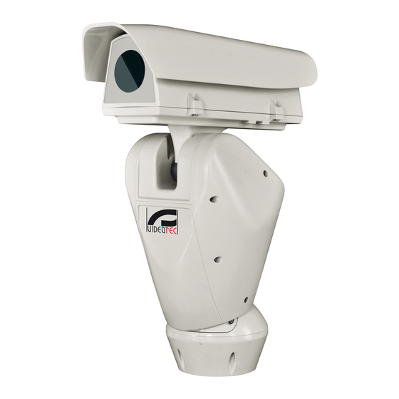
Inhaltszusammenfassung für Videotec ULISSE RADICAL

  • Seite 1 ULISSE RADICAL PTZ unit with integrated Kamera and lens English - Instructions manual Italiano - Manuale di istruzioni Français - Manuel d’instructions Deutsch - Bedienungslanleitung Русский - Руководство по эксплуатации...
  • Seite 3 ULISSE RADICAL PTZ unit with integrated Kamera and lens English - Instructions manual...
  • Seite 5: Inhaltsverzeichnis

    Contents ENGLISH 1 About this manual ......................5 1.1 Typographical conventions ..........................5 2 Notes on copyright and information on trademarks ..........5 3 Safety rules........................5 4 Identification ........................8 4.1 Product description and type designation..................... 8 4.2 Product markings ..............................8 4.2.1 Checking the markings .................................
  • Seite 6 8 Switching on ........................ 22 9 Configuration ....................... 23 9.1 Web interface ................................23 9.1.1 Home ......................................23 9.1.2 User Controls ...................................24 9.1.3 Device Parameters.................................25 9.1.4 Device Statistics ..................................25 9.1.5 Network Configuration ................................25 9.1.6 User Configuration ................................26 9.1.7 Movement Parameters ................................26 9.1.7.1 Autopan .........................................27 9.1.7.2 Patrol ..........................................27 9.1.7.3 Motions Recall ......................................27 9.1.8 Preset Parameters ..................................27...
  • Seite 7: About This Manual

    1 About this manual 3 Safety rules Before installing and using this unit, please read this CAUTION! The electrical system to which manual carefully. Be sure to keep it handy for later the unit is connected must be equipped reference. with a 20A max automatic bipolar circuit breaker.
  • Seite 8 • Before starting any operation, make sure the • Use a Class 2 listed UL tranformer, compliant with power supply is disconnected. the Standards in force, only for products marked UL, powered at 24Vac. • Do not use cables that seem worn or old. •...
  • Seite 9 • Do not allow children or unauthorised people to • Take all necessary precautions to prevent the use the appliance. apparatus from being damaged by electrostatic discharge. • The appliance should only be considered switched off when the power supply has been disconnected •...
  • Seite 10: Identification

    Pan & tilt devices have a label complying with CE markings. designation ULISSE RADICAL is the first ready to use Full HD network PTZ system from Videotec that integrates exceptional combinations of lens and camera, Full HD 1080p, 60fps and 1/2 “ sensor.
  • Seite 11: Versions

    24Vac. guarantee. The pan & tilt can be fitted with bracket for 2 VIDEOTEC LED illuminators for night surveillance The unit must not be dismantled or (illuminators not included). tampered with. The only exceptions...
  • Seite 12: Unpacking

    6.2 Unpacking 6.2.1.2 Remove the protective packaging Open the housing and remove the protective When the product is delivered, make sure that the packaging. package is intact and that there are no signs that it has been dropped or scratched. If there are obvious signs of damage, contact the supplier immediately.
  • Seite 13: Safely Disposing Of Packaging Material

    6.3 Contents 6.5 Preparatory work before installation Check the contents to make sure they correspond with the list of materials as below: 6.5.1 Attaching the bracket • Positioning unit Different types of supports are available (10 • Power supply base Accessories, page 31).
  • Seite 14: Connecting The Cables To The Base

    7 Installation 7.1 Connecting the cables to the base Never, under any circumstances, make any changes or connections that are not Insert the cables into the cable glands holding the shown in this handbook. Failure to follow base at about 20cm from the support. Tighten the the connection instructions that are given cable glands.
  • Seite 15: Fixing The Base To The Support

    7.2 Fixing the base to the support 7.3 Connector board description CONNECTOR BOARD DESCRIPTION Use the screws and the washers supplied with the base. Connector/ Function Component Once you have positioned the gasket (01), fix the Board power supply base (02) onto the bracket (03) with screws (04), Signal cables serrated washers (05) and screw rings (06).
  • Seite 16: Connection Of The Power Supply Line

    7.4 Connection of the power Earth cable should be about 10mm longer supply line than the other two, so that it will not be disconnected accidentally if pulled. Depending on the version, the device can be provided with different power supply voltages. Their The power supply cable should also be value is shown on the product identification label (4.2 covered by the silicone sheath (01) supplied...
  • Seite 17: 24Vac Power Line Connection

    7.4.1 24Vac power line connection 7.4.2 120Vac and 230Vac power line connection Use a Class 2 listed UL tranformer, Cut the cables to the correct length and make the compliant with the Standards in force, only connections. Connect the power supply to the for products marked UL, powered at 24Vac.
  • Seite 18: Connection Of The Alarm Inputs, Of The Twilight Switch And Of The Relays

    7.4.3 Connection of the alarm inputs, of Version with LED illuminators the twilight switch and of the relays CONNECTION OF THE ALARM INPUTS, OF THE TWILIGHT SWITCH AND OF THE RELAYS CAUTION! TNV-1 installation type. The AL1, AL2, Self-powered alarm inputs referred to the installation is type TNV-1, do not connect it AL3, AL4 e AGND shared terminal...
  • Seite 19: Fixing The Upper Body

    7.6 Fixing the upper body Fix the upper body (01) to the base (02) using the fixing screws (03) equipped with gaskets (04). Make sure the base seal is present and in good condition (05). Pay attention to the fixing. Tightening torque: 4Nm.
  • Seite 20: Led Illuminators Installation

    (02). From Pan & Tilt, it is only possible to install VIDEOTEC illuminators. 7.7.1 Fitting the bracket Position the bracket (01) on the bottom of the housing as shown in figure. Install the screws and the washers (02) in the holes (03) and tighten them.
  • Seite 21: Connection Of The Led Illuminators

    7.8 Connection of the LED 7.9 Setting of the LED illuminators illuminators and synchronization mode with the camera Insert the power supply cables through the cable glands by at least 25 cm. Once the adjustment is done the illuminator on the left (MASTER) synchronizes and controls the illuminator 25cm 25cm...
  • Seite 22: Synchronisation With An External Twilight Switch

    7.9.2 Synchronisation with an external • Adjustment of the the illuminator on the right (SLAVE): twilight switch • Lighting threshold: Set the value to the To synchronise the illuminators and camera with an maximum (7.9.5 LED illuminator switching on external light sensitive switch you need to: threshold adjustment, page 21).
  • Seite 23: Led Illuminator Switching On Threshold Adjustment

    7.9.5 LED illuminator switching on 7.9.6 LED illuminator power adjustment threshold adjustment The illuminator on the right must always be set to minimum power. The illuminator on the right must always be set to maximum brightness. The illuminator is set in the factory to provide maximum power.
  • Seite 24: Switching On

    8 Switching on Make sure that all parts are fastened down firmly and safely. Make sure that the unit and other components of the installation are closed The automatic pre-heating (De-Ice) process so that it is impossible to come into contact could be started whenever the device is with live parts.
  • Seite 25: Configuration

    9 Configuration 9.1.1 Home If you log in successfully, the Pan & Tilt management 9.1 Web interface interface will appear. During the first connection assign an address other than 192.168.0.100. Browsers supported: Microsoft Internet Explorer, Google Chrome, Mozilla Firefox. The MAC Address is contained on the label that is on the CPU board.
  • Seite 26: User Controls

    9.1.2 User Controls • Iris close/Iris open/Auto iris To control the Pan & Tilt through the browser, select the User Control entry. A new window will open with a virtual keyboard to enter commands. Fig. 39 • Wiper/Washer Fig. 40 •...
  • Seite 27: Device Parameters

    9.1.3 Device Parameters 9.1.5 Network Configuration From menu entry Device Parameters it is possible From menu entry Network Configuration it is possible to set the name of the pan & tilt and view other to change the setting of the Pan & Tilt network. It is additional information.
  • Seite 28: User Configuration

    9.1.7 Movement Parameters It is also possible to specify if the device needs to be synchronised with an external NTP (Network Time From menu entry Movement Parameters it is Protocol) server. possible to control, via web, all Pan & Tilt parameters. •...
  • Seite 29: Autopan

    9.1.7.1 Autopan 9.1.8 Preset Parameters In the Autopan subsection it is possible to specify the From menu entry Preset Parameters a number of preset autopan start and end.. parameters relative to the presets can be configured: • Scan Speed: The speed, measured in degrees to the second, at which a preset is reached by explicit operator request.
  • Seite 30: Digital I/O

    9.1.10 Digital I/O 9.1.11 Washer In the Digital I/O tab it is possible to configure the The Pan & Tilt wash pump is configured in the Washer digital channels available in Pan & Tilt. What follows is tab where it is possible to associate a preset to the a brief description of the configurable parameters for washing operation, set the duration of washing and each digital input.
  • Seite 31: Camera Parameters

    9.1.12 Camera Parameters 9.1.13 Tools The parameters of the IP camera that were set at From menu entry Tools it is possible to re-set the first start up can be edited in the Camera Parameters predefined values for the entire configuration of Pan section.
  • Seite 32: Factory Default

    9.1.14 Factory Default In order to connect the web camera you must use the program VTTunnel, available in the Tools menu. If the password is no longer available, you When the program starts, a list of networked devices can also restore the factory settings by will be shown.
  • Seite 33: Accessories

    10 Accessories 10.1.1 Washing system connection CAUTION! TNV-1 installation type. The For further details on configuration and installation is type TNV-1, do not connect it use, refer to the relative manual. to SELV circuits. 10.1 Washer CAUTION! In order to reduce the risk of fire, only use cable with sections greater than or The P&T can be equipped with an external pump that equal to 0.13mm²...
  • Seite 34: Wall Mount

    10.2 Wall mount 10.4 Power supply with illuminator control Wall bracket with internal cable channel. Weather-proof box with power supply and control of the illuminators. Fig. 61 Fig. 63 Version of the standard box. 10.3 Parapet bracket Parapet bracket with internal cable channel. Fig.
  • Seite 35: Maintaining

    11 Maintaining 13 Disposal of waste materials Maintenance must be carried out by personnel trained to operate on electrical This symbol mark and recycle system circuits. are applied only to EU countries and not 11.1 Fuses replacement applied to the countries in the other area of the world.
  • Seite 36: Technical Data

    15 Technical data 15.3 Electrical Power supply/Current consumption: 15.1 General • 230Vac, 0.4A, 50/60Hz Built in aluminium and ABS • 24Vac, 4A (8A with LED illuminators), 50/60Hz Epoxypolyester powder painting, RAL9002 colour • 120Vac, 0.8A, 50/60Hz Top mount (OTT) Power consumption: Transmission through toothed belt •...
  • Seite 37: Camera

    15.6 Camera 15.7 Lenses Day/Night Full HD, 60fps, CMOS 1/1.9" sensor Zoom 18x, 8.5-154mm, F2.5 Effective Pixels: 2.38 Megapixel Zoom 33x, 15-500mm, F2.5 (Thermal compensation system and Visible Cut Filter (optional)) Minimum Illumination Zoom 18x, Colour (ICR-OFF): 15.8 Environment • 0.08lx, 50 IRE F2.5, 1/30s Minimum Illumination Zoom 18x, B/W (ICR-ON): Indoor/Outdoor •...
  • Seite 38: Technical Drawings

    16 Technical drawings The dimensions of the drawings are in millimetres. Fig. 65 ULISSE RADICAL, Zoom 18x. MNVCUPKPLUS_1514_EN...
  • Seite 39 Fig. 66 ULISSE RADICAL, Zoom 18x, pre-arranged version for two LED illuminators installation. MNVCUPKPLUS_1514_EN...
  • Seite 40 Email: info@videotec.com Tel. +33 1 60491816 - Fax +33 1 69284736 Email: info.fr@videotec.com Asia Pacific Videotec (HK) Ltd Americas Videotec Security, Inc. Flat 8, 19/F. On Dak Industrial Building, No. 2-6 Wah Sing Street Gateway Industrial Park, 35 Gateway Drive, Suite 100 Kwai Chung, New Territories - Hong Kong Plattsburgh, NY 12901 - U.S.A.
  • Seite 41 ULISSE RADICAL Unità PTZ IP con telecamera ed ottica integrate Italiano - Manuale di istruzioni...
  • Seite 43 Sommario ITALIANO 1 Informazioni sul presente manuale ................7 1.1 Convenzioni tipografiche ............................. 7 2 Note sul copyright e informazioni sui marchi commerciali ........7 3 Norme di sicurezza ......................7 4 Identificazione ......................10 4.1 Descrizione e designazione del prodotto .....................10 4.2 Marcatura del prodotto ............................10 4.2.1 Controllo della marcatura ..............................10 5 Versioni .........................
  • Seite 44 8 Accensione ........................24 9 Configurazione ......................25 9.1 Interfaccia web ...............................25 9.1.1 Home ......................................25 9.1.2 Controlli Utente ..................................26 9.1.3 Parametri Dispositivo ................................27 9.1.4 Statistiche Dispositivo................................27 9.1.5 Configurazione Rete ................................27 9.1.6 Configurazione Utenti .................................28 9.1.7 Parametri Movimento ................................28 9.1.7.1 Autopan .........................................29 9.1.7.2 Patrol ..........................................29 9.1.7.3 Richiamo Movimenti ....................................29 9.1.8 Parametri Preset ..................................29...
  • Seite 45: Informazioni Sul Presente Manuale

    1 Informazioni sul presente 3 Norme di sicurezza manuale ATTENZIONE! L’impianto elettrico al quale è collegata l’unità deve essere dotato di Prima di installare e utilizzare questa unità, leggere un interruttore di protezione bipolare attentamente questo manuale. Conservare questo automatico da 20A max. Tale interruttore manuale a portata di mano come riferimento futuro.
  • Seite 46 • Prima di eseguire qualsiasi operazione assicurarsi • Per i prodotti marcati UL alimentati a 24Vac, di togliere tensione al prodotto. utilizzare un trasformatore UL listed Classe 2, conforme alle normative vigenti. • Non utilizzare cavi con segni di usura o invecchiamento.
  • Seite 47 • Non permettere l’uso dell’apparecchio a bambini o • Adottare le dovute precauzioni per evitare di personale non autorizzato. danneggiare l’apparecchiatura con scariche elettrostatiche. • L’apparecchio si considera disattivato soltanto quando l’alimentazione è stata tolta e i cavi di • L’unità è stata realizzata per essere collegata collegamento con altri dispositivi sono stati con cavo tripolare.
  • Seite 48: Identificazione

    Sui brandeggi è applicata una etichetta conforme alla marcatura CE. del prodotto ULISSE RADICAL é il primo sistema PTZ Full HD di rete di Videotec pronto all'uso che integra eccezionali combinazioni di ottica e telecamera, Full HD 1080p, 60fps e sensori da 1/2".
  • Seite 49: Versioni

    24Vac. garanzia. Il brandeggio può essere dotato di un supporto per montaggio di 2 illuminatori a LED VIDEOTEC per la L'unità non deve essere smontata o visione notturna (illuminatori non inclusi). manomessa. Le uniche eccezioni sono...
  • Seite 50: Disimballaggio

    6.2 Disimballaggio 6.2.1.2 Estrazione dell'imballo protettivo Dopo aver aperto la custodia, estrarre l'imballaggio Alla consegna del prodotto verificare che l'imballo protettivo. sia integro e non abbia segni evidenti di cadute o abrasioni. In caso di evidenti segni di danno all'imballo contattare immediatamente il fornitore.
  • Seite 51: Smaltimento In Sicurezza Dei Materiali Di Imballaggio

    6.3 Contenuto 6.5 Lavoro preparatorio prima dell’installazione Controllare che il contenuto sia corrispondente alla lista del materiale sotto elencata: 6.5.1 Fissaggio del supporto • Unità di posizionamento Sono disponibili diversi tipi di supporto (10 • Base di alimentazione Accessori, pagina 33). Scegliere il supporto adeguato •...
  • Seite 52: Installazione

    7 Installazione 7.1 Collegamento dei cavi alla base Non effettuare per nessun motivo alterazioni o collegamenti non previsti Introdurre i cavi all’interno dei pressacavi tenendo la in questo manuale. Il mancato rispetto base a circa 20cm dal supporto. Serrare i pressacavi. delle indicazioni fornite nel manuale in I pressacavi sono adatti per cavi con diametro merito ai collegamenti può...
  • Seite 53: Fissaggio Della Base Al Supporto

    7.2 Fissaggio della base al 7.3 Descrizione della scheda supporto connettori DESCRIZIONE DELLA SCHEDA CONNETTORI Utilizzare le viti e le rondelle fornite con la base. Connettore/ Funzione Compo- Dopo aver posizionato la guarnizione (01), fissare la nente base (02) sul supporto (03) utilizzando le viti (04), le Alimentazione della scheda rondelle dentellate (05) e gli anelli per vite (06).
  • Seite 54: Collegamento Della Linea Di Alimentazione

    7.4 Collegamento della linea di Il cavo di terra deve essere più lungo degli alimentazione altri due di circa 10mm per prevenirne il distacco accidentale a causa dello A seconda della versione, al dispositivo possono stiramento. essere fornite diverse tensioni di alimentazione. Il loro valore è...
  • Seite 55: Collegamento Della Linea Di Alimentazione In 24Vac

    7.4.1 Collegamento della linea di 7.4.2 Collegamento della linea di alimentazione in 24Vac alimentazione in 120Vac e 230Vac Tagliare a misura i cavi e realizzare i collegamenti. Per i prodotti marcati UL alimentati a 24Vac, Collegare la linea di alimentazione al seguente utilizzare un trasformatore UL listed Classe morsetto: CN1.
  • Seite 56: Collegamento Degli Ingressi Di Allarme, Dell'interruttore Crepuscolare E Dei Relè

    7.4.3 Collegamento degli ingressi di Versione con illuminatori a LED allarme, dell'interruttore crepuscolare e COLLEGAMENTO DEGLI INGRESSI DI ALLARME, DELL'INTERRUTTORE CREPUSCOLARE E DEI RELÈ dei relè AL1, AL2, Ingressi di allarme auto-alimentati riferiti al ATTENZIONE! L'installazione è di tipo TNV-1. AL3, AL4 e morsetto comune AGND Non collegare a circuiti SELV.
  • Seite 57: Fissaggio Del Corpo Superiore

    7.6 Fissaggio del corpo superiore Fissare il corpo superiore (01) alla base (02) tramite le viti di fissaggio (03) dotate di guarnizioni (04). Controllare che sia presente e in buono stato la guarnizione della base (05). Prestare attenzione durante il fissaggio. Coppia di serraggio: 4Nm.
  • Seite 58: Montaggio Degli Illuminatori A Led

    Per un corretto funzionamento si devono sempre installare entrambi gli illuminatori. Sul brandeggio è possibile installare esclusivamente illuminatori VIDEOTEC. 7.7.1 Montaggio della staffa Posizionare la staffa (01) sulla parte inferiore della custodia come illustrato in figura. Inserire le viti e le rondelle (02) nei fori (03) e serrarle.
  • Seite 59: Collegamento Degli Illuminatori A Led

    7.8 Collegamento degli 7.9 Regolazione degli illuminatori a LED illuminatori a LED e modalità di sincronizzazione con la Inserire i cavi di alimentazione per almeno 25cm attraverso i pressacavi. telecamera Una volta effettuata la regolazione 25cm 25cm l'illuminatore di sinistra (MASTER) sincronizza e controlla l'illuminatore di destra (SLAVE).
  • Seite 60: Sincronizzazione Con Un Interruttore Crepuscolare Esterno

    7.9.2 Sincronizzazione con un • Regolare l'illuminatore destro (SLAVE): interruttore crepuscolare esterno • Soglia di accensione: Impostare il valore al massimo (7.9.5 Regolazione della soglia di Per sincronizzare gli illuminatori e la telecamera con accensione degli illuminatori a LED, pagina 23). un crepuscolare esterno è...
  • Seite 61: Regolazione Della Soglia Di Accensione Degli Illuminatori A Led

    7.9.5 Regolazione della soglia di 7.9.6 Regolazione della potenza degli accensione degli illuminatori a LED illuminatori a LED L'illuminatore destro deve sempre essere L'illuminatore destro deve sempre essere impostato a luminosità massima. impostato a potenza minima. L'illuminatore è regolato in fabbrica per erogare la massima potenza.
  • Seite 62 8 Accensione Accertarsi che tutte le parti siano fissate in maniera solida ed affidabile. Assicurarsi che l'unità e gli altri componenti dell’impianto siano chiusi in modo idoneo a La procedura di preriscaldamento impedire il contatto con componenti sotto automatico (De-Ice) si potrebbe attivare tensione.
  • Seite 63: Interfaccia Web

    9 Configurazione 9.1.1 Home Se il login viene effettuato con successo verrà 9.1 Interfaccia web mostrata l'interfaccia di gestione del brandeggio. Alla prima connessione assegnare un indirizzo diverso da 192.168.0.100. Browser supportati: Microsoft Internet Explorer, Google Chrome, Mozilla Firefox. Il MAC Address è riportato sull’etichetta presente sulla scheda CPU.
  • Seite 64: Controlli Utente

    9.1.2 Controlli Utente • Iris close/Iris open/Auto iris Per controllare il brandeggio via browser, selezionare la voce Controlli Utente. Si aprirà una nuova finestra con una tastiera virtuale per inviare i comandi. Fig. 39 • Wiper/Washer Fig. 40 • Day: Attiva il filtro IR della camera. Se presenti, spegne gli illuminatori a LED.
  • Seite 65: Parametri Dispositivo

    9.1.3 Parametri Dispositivo 9.1.5 Configurazione Rete Alla voce del menu Parametri Dispositivo è possibile Alla voce del menu Configurazione Rete è possibile impostare il nome del brandeggio e visualizzare altre cambiare l'impostazione di rete del brandeggio. È informazioni aggiuntive. possibile decidere se il dispositivo debba avere un indirizzo assegnato staticamente, dinamicamente con DHCP o autogenerato.
  • Seite 66: Configurazione Utenti

    9.1.7 Parametri Movimento È possibile inoltre specificare se il dispositivo debba sincronizzarsi con un server NTP (Network Time Alla voce del menu Parametri Movimento è possibile Protocol) esterno. controllare via web tutti i parametri del brandeggio. • NTP -> DISABILITATO: Selezionare questa opzione •...
  • Seite 67: Autopan

    9.1.7.1 Autopan 9.1.8 Parametri Preset Nella sottosezione Autopan e possibile specificare il Alla voce del menu Parametri Preset sono preset di inizio e di fine dell'autopan. configurabili alcuni parametri relativi ai preset: • Velocità Scan: La velocità in gradi al secondo con cui viene raggiunto un preset su richiesta esplicita dell'operatore.
  • Seite 68: I/O Digitali

    9.1.10 I/O Digitali 9.1.11 Washer Nella scheda I/O Digitali è possibile configurare i La pompa per il lavaggio del brandeggio è canali digitali presenti nel brandeggio. Segue una configurata nella scheda Washer dove è possibile breve descrizione dei parametri configurabili per associare un preset all'operazione di lavaggio, ciascun ingresso digitale.
  • Seite 69: Parametri Camera

    9.1.12 Parametri Camera 9.1.13 Strumenti I parametri della camera IP che sono stato impostati Alla voce del menu Strumenti è possibile reimpostare al primo avvio sono modificabili alla voce del menu i valori predefiniti per tutta la configurazione del Parametri Camera. Alla voce del menu Parametri brandeggio o solo per alcune sezioni specifiche.
  • Seite 70: Factory Default

    9.1.14 Factory Default Per potersi connettere all'interfaccia web della telecamera è necessario utilizzare l'applicativo Se la password di accesso non è più VTTunnel, avviabile dalla voce di menu Strumenti. disponibile, è possibile ripristinare le All'avvio dell'applicativo verrà mostrato un elenco di impostazioni di fabbrica tramite un tasto di dispositivi collegati in rete.
  • Seite 71: Accessori

    10 Accessori 10.1.1 Collegamento dell'impianto di lavaggio Per ulteriori dettagli sulla configurazione ATTENZIONE! L'installazione è di tipo TNV-1. e l’utilizzo fare riferimento al manuale del Non collegare a circuiti SELV. relativo accessorio. ATTENZIONE! Per ridurre il rischio di 10.1 Impianto di lavaggio incendio usare solamente cavi aventi sezioni maggiori o uguali a 0.13mm²...
  • Seite 72: Supporto Da Parete

    10.2 Supporto da parete 10.4 Alimentatore con controllo degli illuminatori Supporto per montaggio a parete con passaggio interno cavi. Scatola stagna con alimentatore e controllo degli illuminatori. Fig. 63 Versione della scatola standard. Fig. 61 10.3 Supporto da parapetto Supporto per montaggio a parapetto con passaggio interno cavi.
  • Seite 73: Manutenzione

    11 Manutenzione 13 Smaltimento dei rifiuti La manutenzione deve essere eseguita solo Questo simbolo e il sistema di riciclaggio da personale qualificato ad intervenire su sono validi solo nei paesi dell'EU e non circuiti elettrici. trovano applicazione in altri paesi del mondo.
  • Seite 74: Dati Tecnici

    15 Dati tecnici 15.3 Elettrico Tensione di alimentazione/Corrente assorbita: 15.1 Generale • 230Vac, 0.4A, 50/60Hz Costruzione in pressofusione di alluminio e ABS • 24Vac, 4A (8A con illuminatori a LED), 50/60Hz Verniciatura a polveri di epossipoliestere, colore • 120Vac, 0.8A, 50/60Hz RAL9002 Potenza assorbita: Top mount (OTT)
  • Seite 75: Telecamere

    15.6 Telecamere 15.7 Ottiche Day/Night Full HD, 60fps, sensore CMOS 1/1.9" Zoom 18x, 8.5-154mm, F2.5 Pixels Effettivi: 2.38 Megapixel Zoom 33x, 15-500mm, F2.5 (Sistema di compensazione termica e filtro anti riverbero -Visibile Illuminazione Minima zoom 18x, colore (ICR-OFF): Cut Filter- opzionali) •...
  • Seite 76: Disegni Tecnici

    16 Disegni tecnici Le dimensioni dei disegni sono espresse in millimetri. AREA AREA UTILE UTILE B - B A - A AREA UTILE Fig. 65 ULISSE RADICAL, Zoom 18x. MNVCUPKPLUS_1514_IT...
  • Seite 77 AREA AREA UTILE UTILE B - B A - A AREA UTILE Fig. 66 ULISSE RADICAL, Zoom 18x, versione con predisposizione per il montaggio di due illuminatori a LED. MNVCUPKPLUS_1514_IT...
  • Seite 78 Email: info@videotec.com Tel. +33 1 60491816 - Fax +33 1 69284736 Email: info.fr@videotec.com Asia Pacific Videotec (HK) Ltd Americas Videotec Security, Inc. Flat 8, 19/F. On Dak Industrial Building, No. 2-6 Wah Sing Street Gateway Industrial Park, 35 Gateway Drive, Suite 100 Kwai Chung, New Territories - Hong Kong Plattsburgh, NY 12901 - U.S.A.
  • Seite 79 ULISSE RADICAL Unité PTZ avec caméra et objectif intégrés Français - Manuel d’instructions...
  • Seite 81 Sommaire FRANÇAIS 1 À propos de ce mode d’emploi ..................5 1.1 Conventions typographiques ..........................5 2 Notes sur le copyright et informations sur les marques de commerce ..... 5 3 Normes de securité ......................5 4 Identification ........................8 4.1 Description et désignation du produit ......................
  • Seite 82 8 Allumage ........................22 9 Configuration ....................... 23 9.1 Interface web ................................23 9.1.1 Home ......................................23 9.1.2 Contrôles Utilisateur ................................24 9.1.3 Paramètres Dispositif ................................25 9.1.4 Statistiques Dispositif ................................25 9.1.5 Configuration Réseau................................25 9.1.6 Configuration Utilisateurs ..............................26 9.1.7 Paramètres Mouvement ..............................26 9.1.7.1 Autopan .........................................27 9.1.7.2 Patrol ..........................................27 9.1.7.3 Rappel Mouvements ....................................27 9.1.8 Paramètres Preset ..................................27...
  • Seite 83: Propos De Ce Mode D'emploi

    1 À propos de ce mode 3 Normes de securité d’emploi ATTENTION! Le circuit électrique auquel l'unité est reliée doit être équipé d'un Avant d’installer et d’utiliser cet appareil, veuillez interrupteur de protection bipolaire lire attentivement ce mode d’emploi. Conservez-le à automatique de 20A max.
  • Seite 84 • Sectionner l'alimentation avant de procéder à • Il faut, uniquement pour les produits marqués UL toute opération. alimentés à 24Vac, utiliser un transformateur UL listed Classe 2, conforme aux normes en vigueur. • Ne pas utiliser de câbles usés ou endommagés. •...
  • Seite 85 • Ne pas laisser l'appareil à portée des enfants ou de • Adopter les précautions utiles pour éviter personnes non autorisées. d'endommager l'appareil à la suite de décharges électrostatiques. • L’appareil ne doit être considéré comme désactivé qu'avec l'alimentation sectionnée et les câbles de •...
  • Seite 86: Identification

    PTZ peut être équipée d'un caisson avec des optiques de 18x ou 33 x. ULISSE RADICAL est certifié ONVIF Profil S, il est donc compatible avec la plupart des VMS sur le marché : pour un contrôle complet, l'unité implémente les Fig.
  • Seite 87: Versions

    24Vac. l’annulation de la garantie. La tourelle peut être munie d’un support pour l’utilisation de 2 projecteurs à LED VIDEOTEC pour L'unité ne doit être ni démontée ni altérée. vision nocturne (projecteurs à prévoir en plus). Les seules exceptions concernent les opérations de montage et d'entretien...
  • Seite 88: Déballage

    6.2 Déballage 6.2.1.2 Extraction de l'emballage de protection Lors de la livraison du produit, vérifier que Après avoir ouvert le caisson, extraire l'emballage de l’emballage est en bon état et l’absence de tout signe protection. évident de chute ou d’abrasion. En cas de dommages évidents, contacter immédiatement le fournisseur.
  • Seite 89: Élimination Sans Danger Des Matériaux D'emballage

    6.3 Contenu 6.5 Opérations à effectuer avant l’installation Contrôler que le contenu correspond à la liste matériel indiquée ci-dessous: 6.5.1 Fixation du support • Unité de positionnement Plusieurs types de supports sont disponibles (10 • Base d'alimentation Accessoires, page 31). Choisir le support convenable •...
  • Seite 90: Installation

    7 Installation 7.1 Connexion des câbles à la base Ne procéder sous aucun prétexte à des modifications ou des connexions non Passer les câbles dans les presse-câbles en prévues dans ce manuel. L’utilisation maintenant la base à environ 20cm du support. Serrer d’appareils inadéquats peut comporter les presse-étoupes.
  • Seite 91: Fixage De La Base Au Support

    7.2 Fixage de la base au support 7.3 Description de la carte de connexion Utiliser les vis et les rondelles fournies avec la base. DESCRIPTION DE LA CARTE DE CONNEXION Connecteur/ Fonction Après avoir positionné le joint (01), fixer la base (02) Composant au support (03) en utilisant les vis (04), les rondelles à...
  • Seite 92: Connexion De La Ligne D'alimentation

    7.4 Connexion de la ligne Le câble de terre doit être plus long des d'alimentation deux autres d'environ 10mm pour éviter tout détachement accidentel. Selon la version, différentes tensions d'alimentation peuvent être fournies au dispositif. Leur valeur est Le câble d'alimentation doit en outre être indiquée sur l'étiquette d'identification du produit ( couvert de la gaine en silicone (01) fournie.
  • Seite 93: Connexion De La Ligne D'alimentation En 24Vac

    7.4.1 Connexion de la ligne 7.4.2 Raccordement de la ligne d'alimentation en 24Vac d'alimentation en 120Vac et 230Vac Couper les câbles à la longueur nécessaire et Il faut, uniquement pour les produits procéder aux connexions. Connecter la ligne marqués UL alimentés à 24Vac, utiliser un d'alimentation avec la borne: CN1.
  • Seite 94: Branchement Des Entrées D'alarme, De L'interrupteur Crépusculaire Et Des Relais

    7.4.3 Branchement des entrées Version avec projecteurs à LED d'alarme, de l'interrupteur crépusculaire BRANCHEMENT DES ENTRÉES D'ALARME, DE L'INTERRUPTEUR CRÉPUSCULAIRE ET DES RELAIS et des relais AL1, AL2, Entrées d'alarme auto-alimentées relatives à ATTENTION! L'installation est du type TNV- AL3, AL4 e la borne commune AGND.
  • Seite 95: Fixation Du Corps Supérieur

    7.6 Fixation du corps supérieur Fixer le corps supérieur (01) à la base (02) au moyen des vis de fixation (03) pourvues de joints (04). Contrôler que le joint de la base est en place et en bon état (05). Faire attention pendant la fixation.
  • Seite 96: Montage Des Projecteurs À Led

    (02). Pour en correct fonctionnement les deux projecteurs doivent toujours être montés ensemble. Seuls des projecteurs VIDEOTEC peuvent être installés sur la tourelle. 7.7.1 Montage de l’étrier Positionner l’étrier (01) sur la partie inférieure du caisson comme illustré en figure. Introduire les vis et les rondelles (02) dans les trous (03) et les serrer.
  • Seite 97: Branchement Des Projecteur À Led

    7.8 Branchement des projecteur 7.9 Reglage des projecteurs à LED à LED et modalité de synchronisation avec la caméra Introduire les câbles d'alimentation de 25 cm au moins à travers les presse-étoupes. Une fois effectué le réglage, le projecteur de gauche (MASTER) synchronise et contrôle le projecteur de droite (SLAVE).
  • Seite 98: Synchronisation Avec Un Interrupteur Crépusculaire Externe

    7.9.2 Synchronisation avec un • Réglage du projecteur de droite (SLAVE): interrupteur crépusculaire externe • Seuil d'allumage: Configurer la valeur au maximum (7.9.5 Réglage du seuil d'allumage Pour synchroniser les illuminateurs et la caméra avec des projecteurs à LED, page 21). un crépusculaire externe, procéder comme suit: •...
  • Seite 99: Réglage Du Seuil D'allumage Des Projecteurs À Led

    7.9.5 Réglage du seuil d'allumage des 7.9.6 Réglage de la puissance des projecteurs à LED projecteurs à LED Le projecteur de droite doit toujours être Le projecteur de droite doit toujours être configuré à la luminosité maximum. configuré à la puissance minimum. Le projecteur est réglé...
  • Seite 100: Allumage

    8 Allumage Ne pas stationner à proximité du dispositif sous tension. N'intervenir sur le dispositif S'assurer que l'unité et les autres qu'avec l'alimentation coupée. composants de l'installation soient fermés de façon à empêcher le contact avec les La procédure de préchauffage automatique composants sous tension.
  • Seite 101: Interface Web

    9 Configuration 9.1.1 Home Si le login est effectué avec succès, on pourra voir 9.1 Interface web l'interface de gestion de la tourelle. À la première connexion, donner une adresse différente de 192.168.0.100. Logiciels de navigation supportés: Microsoft Internet Explorer, Google Chrome, Mozilla Firefox.
  • Seite 102: Contrôles Utilisateur

    9.1.2 Contrôles Utilisateur • Iris close/Iris open/Auto iris Pour contrôler la tourelle par navigateur, sélectionner la mention Contrôle Utilisateur. Une nouvelle fenêtre s'ouvrira, avec un clavier virtuel pour sélectionner les commandes. Fig. 39 • Wiper/Washer Fig. 40 • Day: Activer le filtre IR de la chambre. Si présents, éteint les projecteurs à...
  • Seite 103: Paramètres Dispositif

    9.1.3 Paramètres Dispositif 9.1.5 Configuration Réseau A la mention du menu Paramètres Dispositif il est A la mention du menu Configuration Réseau il est possible de configurer le nom de la tourelle et possible de changer la configuration de réseau de d'afficher d'autres informations supplementaire.
  • Seite 104: Configuration Utilisateurs

    9.1.7 Paramètres Mouvement Il est également possible de mentionner si le dispositif doit se synchroniser avec un serveur NTP A la mention du menu Paramètres Mouvement il est (Network Time Protocol) externe. possible de contrôler par web tous les paramètres de •...
  • Seite 105: Autopan

    9.1.7.1 Autopan 9.1.8 Paramètres Preset Dans la sous-section Autopan il est possible A la mention du menu Paramètres Preset on peut d'indiquer le preset de début et de fin de l'autopan. configurer certains paramètres concernant les preset: • Vitesse Scan: La vitesse en degrés à la seconde, avec laquelle un preset est atteint, sur demande explicite de l'opérateur.
  • Seite 106: I/O Digitaux

    9.1.10 I/O Digitaux 9.1.11 Washer Dans la carte I/O Digitaux il est possible de configurer La pompe pour le lavage de la tourelle est configurée les canaux digitaux présents dans la tourelle. Il y a dans la carte Washer, où il est possible d'associer un ci-dessous une courte description des paramètres preset à...
  • Seite 107: Paramètres Caméra

    9.1.12 Paramètres Caméra 9.1.13 Instruments Les paramètres de la caméra IP qui ont été configurés A la mention du menu Instruments il est possible à la première mise en marche sont modifiables de reconfigurer les valeurs prédéfinies pour toute dans la section Paramètres Caméra. Dans la section la configuration de la tourelle ou seulement pour Paramètres Caméra il est possible également certaines sections spécifiques.
  • Seite 108: Factory Default

    9.1.14 Factory Default Afin de connecter la caméra IP, vous devez utiliser le programme de VTTunnel, démarrable du menu Si le mot de passe ne est plus disponible, Instruments. il est possible de rétablir les paramétrages Au lancement du programme, sera montrée une d’usine à...
  • Seite 109: Accessoires

    10 Accessoires 10.1.1 Branchement du système de lavage Pour de plus amples informations sur la ATTENTION! L'installation est du type TNV- configuration et l'utilisation, consulter le 1. Ne pas la connecter à des circuits SELV. manuel de l'accessoire correspondant. ATTENTION! Pour réduire les risques 10.1 Système de lavage d’incendie, utiliser uniquement des câbles de sections égales ou supérieures à...
  • Seite 110: Support Fixation Murale

    10.2 Support fixation murale 10.4 Alimentateur avec contrôle des projecteurs. Support mural avec passage interne des câbles. Boîte étanche avec alimentateur et contrôle des projecteurs. Fig. 61 Fig. 63 Version du boîtier standard. 10.3 Support fixation sol Support de fixation au sol avec passage interne des câbles.
  • Seite 111: Entretien

    11 Entretien 13 Élimination des déchets L’entretien doit être uniquement effectué Ce symbole et le système de recyclage ne par un personnel qualifié en matière de sont appliqués que dans les pays UE et non circuits électriques. dans les autres pays du monde. Votre produit est conçu et fabriqué...
  • Seite 112: Données Techniques

    15 Données techniques 15.3 Électrique Tension d’alimentation/Courant absorbé: 15.1 Généralités • 230Vac, 0.4A, 50/60Hz Fabriqué en fonte d’aluminium et en ABS • 24Vac, 4A (8A pour projecteurs à LED), 50/60Hz Vernissage avec poudres époxypolyester, couleur • 120Vac, 0.8A, 50/60Hz RAL9002 Puissance absorbée: Caisson positionné...
  • Seite 113: Caméra

    15.6 Caméra 15.7 Optiques Day/Night Full HD, 60fps, CMOS 1/1.9" capteur Zoom 18x, 8.5-154mm, F2.5 Pixels effectifs: 2.38 Megapixel Zoom 33x, 15-500mm, F2.5 (Système de compensation thermique et filtre anti-éblouissement Illumination minimum Zoom 18x, Couleur (ICR-OFF): - Visible Cut Filter - options) •...
  • Seite 114: Dessins Techniques

    16 Dessins techniques Les dimensions des dessins sont exprimées en millimètres. Fig. 65 ULISSE RADICAL, Zoom 18x. MNVCUPKPLUS_1514_FR...
  • Seite 115 Fig. 66 ULISSE RADICAL, Zoom 18x, version avec prédisposition pour le montage des deux projecteurs à LED. MNVCUPKPLUS_1514_FR...
  • Seite 116 Email: info@videotec.com Tel. +33 1 60491816 - Fax +33 1 69284736 Email: info.fr@videotec.com Asia Pacific Videotec (HK) Ltd Americas Videotec Security, Inc. Flat 8, 19/F. On Dak Industrial Building, No. 2-6 Wah Sing Street Gateway Industrial Park, 35 Gateway Drive, Suite 100 Kwai Chung, New Territories - Hong Kong Plattsburgh, NY 12901 - U.S.A.
  • Seite 117 ULISSE RADICAL PTZ Einheit mit integrierten Kamera und Optik Deutsch - Bedienungslanleitung...
  • Seite 118 8 Einschaltung ........................ 22 9 Konfiguration ....................... 23 9.1 Web-Schnittstelle ..............................23 9.1.1 Home ......................................23 9.1.2 Benutzersteuerung ................................24 9.1.3 Geräteparameter ...................................25 9.1.4 Gerätestatistiken ..................................25 9.1.5 Netzwerk-Konfiguration ..............................25 9.1.6 Benutzer-Konfiguration ...............................26 9.1.7 Bewegungsparameter .................................26 9.1.7.1 Autopan .........................................27 9.1.7.2 Patrol ..........................................27 9.1.7.3 Bewegungsanforderung ..................................27 9.1.8 Preset-Parameter ...................................27 9.1.9 Preset-Parameter (Erweitert) .............................27 9.1.10 Digitale I/O.....................................28...
  • Seite 119 Inhaltsverzeichnis DEUTSCH 1 Allgemeines ........................5 1.1 Schreibweisen ................................5 2 Anmerkungen zum Copyright und Informationen zu den Handelsmarken ..... 5 3 Sicherheitsnormen ......................5 4 Identifizierung ....................... 8 4.1 Beschreibung und Bezeichnung des Produktes ................... 8 4.2 Kennzeichnung des Produkts..........................8 4.2.1 Prüfung der Kennzeichnung ...............................
  • Seite 120 MNVCUPKPLUS_1514_DE...
  • Seite 121: Allgemeines

    1 Allgemeines 3 Sicherheitsnormen Lesen Sie bitte vor dem Installieren und dem ACHTUNG! Die elektrische Anlage, an Verwenden dieses Gerätes die Bedienungsanleitung der die Einheit angeschlossen ist, muss sorgfältig durch. Bewahren Sie sie zum späteren mit einem automatischen zweipoligen Nachschlagen auf. Schutzschalter 20A max ausgestattet 1.1 Schreibweisen sein.
  • Seite 122 • Unterbrechen Sie die Stromversorgung, bevor die • Lediglich für die Produkte mit UL - Markierung mit beschriebenen Arbeiten durchgeführt werden. 24Vac - Versorgung ein UL - Speisetransformator der Klasse 2 verwenden, welches den geltenden • Es dürfen keine Kabel mit Verschleiß- oder Richtlinien entspricht.
  • Seite 123 • Kindern oder unbefugten Personen ist der • Vermeiden Sie durch gebotene Vorkehrungen, Gebrauch des Gerätes zu untersagen. dass das Gerät durch elektrostatische Entladungen beschädigt wird. • Das Gerät gilt erst dann als deaktiviert, wenn die Stromversorgung ausgeschaltet und die •...
  • Seite 124: Identifizierung

    Abstände bis 200m erreicht, bleiben die Leistungen kontrollieren, ob das gelieferte Material den optimal auch bei vollständiger Dunkelheit. jeweiligen Anforderungen entspricht. Zu erkennen ist ULISSE RADICAL hat eine Herstellergarantie von 3 dies anhand der Kennzeichnungsschilder. Jahren ohne Beschränkungen, inklusiv Videokamera Unter keinen Umständen dürfen Veränderungen und Motoren.
  • Seite 125: Versionen

    Spannung von 24Vac der Gewährleistungsrechte. betrieben werden. Der S-N-Kopf kann mit einer Halterung Die Einheit darf nicht auseinandergebaut für 2 VIDEOTEC LED- Scheinwerfer für die werden, und es dürfen keine Nachtüberwachung (Scheinwerfer nicht Veränderungen daran vorgenommen eingeschlossen).
  • Seite 126: Entfernen Der Verpackung

    6.2 Entfernen der Verpackung 6.2.1.2 Herausziehen der Schutzverpackung Nach Öffnen des Gehäuse, die Schutzverpackung Bei der Lieferung des Produktes ist zu prüfen, ob die herausziehen. Verpackung intakt ist oder offensichtliche Anzeichen von Stürzen oder Abrieb aufweist. Bei offensichtlichen Schadensspuren an der Verpackung muss umgehend der Lieferant verständigt werden.
  • Seite 127: Sichere Entsorgung Der Verpackungsmaterialien

    6.3 Inhalt 6.5 Auf die Installation vorbereitende Tätigkeiten Prüfen Sie, ob der Inhalt mit der nachstehenden Materialliste übereinstimmt: 6.5.1 Befestigung der Halterung • Positionierungseinheit Verschiedene Halterungen sind (10 Zubehör, Seite  • Basis für Netzstromversorgung 31). Das geeignetste für die Installation auswählen •...
  • Seite 128: Installation

    7 Installation 7.1 Anschließen der Kabel an die Basis Unter keinen Umständen dürfen Veränderungen oder Anschlüsse Die Kabel in den Kabelschellen einführen, während vorgenommen werden, die in diesem die Basis etwa 20cm von der Halterung entfernt Handbuch nicht genannt sind. Die gehalten wird.
  • Seite 129: Befestigung Der Basis An Der Halterung

    7.2 Befestigung der Basis an der 7.3 Beschreibung der Karte Halterung Anschlüsse BESCHREIBUNG DER KARTE ANSCHLÜSSE Verwenden Sie die mit der Basis gelieferten Schrauben und Unterlegscheiben. Verbinder/ Funktion Kompo- Nach der Positionierung der Dichtung (01), die Basis nente (02) mit den Schrauben (04), den Zahnscheiben (05) Platinenversorgung und den Ringen für Schrauben (06) an der Halterung Signalkabel...
  • Seite 130: Anschluss Der Stromversorgung

    7.4 Anschluss der Das Erdungskabel muss um etwa 10mm Stromversorgung länger sein, als die anderen beiden Kabel, um das ungewollte Lösen durch Ziehen des Je nach Version kann die Vorrichtung mit Kabels zu verhindern. unterschiedlichen Versorgungsspannungen geliefert werden. Der Wert ist auf dem Kennzeichnungsschild Ferner muss das Versorgungskabel von des Produktes angegeben (4.2 Kennzeichnung des einer Silikonummantelung (01) überzogen...
  • Seite 131: Anschluss Der Stromversorgunglinie 24Vac

    7.4.1 Anschluss der 7.4.2 Anschluss der Versorgungsleitung Stromversorgunglinie 24Vac in 120Vac und 230Vac Die Kabel zuschneiden und die unten beschriebenen Lediglich für die Produkte mit UL - Anschlüsse vornehmen. Die Versorgungsleitung am Markierung mit 24Vac - Versorgung ein Klemmen anschließen: CN1. UL - Speisetransformator der Klasse 2 verwenden, welches den geltenden Richtlinien entspricht.
  • Seite 132: Anschluss Der Alarmeingänge, Der Dämmerungsschalter Und Der Relais

    7.4.3 Anschluss der Alarmeingänge, der Version mit LED- Scheinwerfern Dämmerungsschalter und der Relais ANSCHLUSS DER ALARMEINGÄNGE, DER DÄMMERUNGSSCHALTER UND DER RELAIS ACHTUNG! Die Anlage gehört zum Typ TNV- AL1, AL2, Sich selbstversorgende Alarmeingänge, 1. Nicht an Kreisläufe SELV anschließen. AL3, AL4 e bezogen auf gemeinsame Klemme AGND.
  • Seite 133: Befestigung Des Oberen Körpers

    7.6 Befestigung des oberen Körpers Den oberen Körper (01) mit den Spannschrauben (03) und Dichtungen (04) an der Basis (02) befestigen. Prüfen Sie, ob die Dichtung (05) der Basis vorhanden und in einwandfreiem Zustand ist. Abb. 21 Auf die Befestigung achten. Anzugsdrehmoment: 4Nm.
  • Seite 134: Montage Der Scheinwerfer Mit Led

    Bügels (02) anbringen. Aus funktionstechnischen Gründen müssen stets beide Scheinwerfer zusammen montiert werden. Am Schwenk-Neige-Kopf dürfen nur Scheinwerfer von VIDEOTEC installiert werden. 7.7.1 Bügelmontage Den Bügel (01) im unteren Teil des Gehäuses positionieren, wie in der Abbildung gezeigt. Die Schrauben und die Unterlegescheiben (02) in die Bohrungen (03) einfügen und festziehen.
  • Seite 135: Anschluss Der Led-Scheinwerfer

    7.8 Anschluss der LED- 7.9 Einstellung der Scheinwerfer LED-Scheinwerfer und Vorgehensweise zur Die Versorgungskabel um mindestens 25 cm durch die Kabelschellen stecken. Gleichschaltung mit der Kamera Nach der Regelung synchronisiert und 25cm 25cm steuert der linke Scheinwerfer (MASTER ) den rechten Scheinwerfer (SLAVE). Der Dämmerungsschalter ermittelt das Licht in der Umgebung und kontrolliert das Ein- und Ausschalten der Scheinwerfer, wenn die Helligkeit das vom...
  • Seite 136: Synchronisierung Mit Einem Externen Dämmerungsschalter

    7.9.2 Synchronisierung mit einem • Regelung des rechten Scheinwerfers (SLAVE): externen Dämmerungsschalter • Einschaltschwelle: Wert auf Maximum einstellen (7.9.5 Einstellung der Die Scheinwerfer und die Kamera werden Einschaltschwelle der LED-Scheinwerfer., Seite  folgendermaßen mit einem externen 21). Dämmerungsschalter synchronisiert: • Infrarotleistung: Wert auf Minimum einstellen •...
  • Seite 137: Einstellung Der Einschaltschwelle Der Led-Scheinwerfer

    7.9.5 Einstellung der Einschaltschwelle 7.9.6 Einstellung der Leistung der LED- der LED-Scheinwerfer. Scheinwerfer. Der rechte Scheinwerfer muss immer auf Der rechte Scheinwerfer muss immer auf die maximale Helligkeit eingestellt sein. die minimale Leistung eingestellt sein. Der Scheinwerfer wird im Werk zur Erbringung maximaler Leistung eingestellt.
  • Seite 138: Einschaltung

    8 Einschaltung Vergewissern Sie sich, dass alle Teile solide und zuverlässig befestigt sind. Sicherstellen, das die Einheit und die anderen Bauteile der Anlage korrekt Der automatische Vorheizvorgang (De-Ice) geschlossen sind, um den Kontakt mit könnte immer dann aktiviert werden, wenn unter Spannung stehenden Bauteilen zu das Gerät bei einer Umgebungstemperatur verhindern.
  • Seite 139: Konfiguration

    9 Konfiguration 9.1.1 Home Wenn die Anmeldung erfolgreich war, öffnet sich 9.1 Web-Schnittstelle die Schnittstelle zur Steuerung des Schwenk-Neige- Kopfes. Beim ersten Anschluss eine Adresse zuweisen, die nicht 192.168.0.100 ist. Unterstützte Browser: Microsoft Internet Explorer, Google Chrome, Mozilla Firefox. Die MAC Address wird auf dem Etikett an der CPU-Karte angegeben.
  • Seite 140: Benutzersteuerung

    9.1.2 Benutzersteuerung • Iris close/Iris open/Auto iris Um den Schwenk-Neige-Kopf via Browser zu steuern, wählen Sie den Eintrag Benutzersteuerung. Es öffnet sich ein neues Fenster mit einer virtuellen Tastatur zum Absenden von Befehlen. Abb. 39 • Wiper/Washer Abb. 40 • Day: Aktivierung Filter IR der Kamera. Falls vorhanden, werden die LED- Scheinwerfer ausgeschaltet.
  • Seite 141: Geräteparameter

    9.1.3 Geräteparameter 9.1.5 Netzwerk-Konfiguration Im Menü-Eintrag Geräteparameter können der Name Im Menü-Eintrag Netzwerk-Konfiguration kann die des Schwenk-Neige-Kopfes eingestellt und andere Netzwerk-Einstellung des Schwenk-Neige-Kopfes Zusatzinformationen angezeigt werden. geändert werden. Es kann eingestellt werden, ob das Gerät eine statisch oder dynamisch mit DHCP zugewiesene oder eine selbstgenerierte Adresse haben muss.
  • Seite 142: Benutzer-Konfiguration

    9.1.7 Bewegungsparameter Außerdem kann angegeben werden, ob das Gerät sich mit einem externen NTP (Network Time Protocol) Im Menü-Eintrag Bewegungsparameter können via Server synchronisieren muss. Internet alle Parameter des Schwenk-Neige-Kopfes • NTP -> DEAKTIVIERT: Stellen Sie diese Option kontrolliert werden. ein, wenn Datum und Uhrzeit des Geräts nicht •...
  • Seite 143: Autopan

    9.1.7.1 Autopan 9.1.8 Preset-Parameter Im Unterabschnitt Autopan können die Presets für Im Menü-Eintrag Preset-Parameter sind einige Beginn und Ende des Autopan angegeben werden. Parameter der Presets konfigurierbar: • Scan Geschwindigkeit: Geschwindigkeit in Grad pro Sekunde, mit der ein Preset auf ausdrückliche Aufforderung des Bedieners erreicht wird.
  • Seite 144: Digitale I/O

    9.1.10 Digitale I/O 9.1.11 Washer In der Registerkarte Digitale I/O können die digitalen Die Pumpe für die Waschanlage des Schwenk-Neige- Kanäle des Schwenk-Neige-Kopfes konfiguriert Kopfes wird in der Registerkarte Washer konfiguriert, werden. Es folgt eine kurze Beschreibung der in der mit dem Waschvorgang ein Preset verknüpft, konfigurierbaren Parameter für jeden Digitaleingang.
  • Seite 145: Kamera-Parameter

    9.1.12 Kamera-Parameter 9.1.13 Werkzeuge Die Parameter der IP-Kamera, die beim ersten Start Im Menü-Eintrag Werkzeuge können die gesamte eingestellt wurden, können im Abschnitt Kamera- Konfiguration des Schwenk-Neige-Kopfes oder nur Parameter geändert werden. Im Abschnitt Kamera- bestimmte Abschnitte auf die vordefinierten Werte Parameter können außerdem der Zoomfaktor und zurückgesetzt werden.
  • Seite 146: Factory Default

    9.1.14 Factory Default Um die IP-Kamera anzuschließen, müssen Sie das VTTunnel- Programm verwenden, aus dem Menü Falls das Kennwort nicht mehr verfügbar Werkzeuge bootfähig. ist, können mit einer Resettaste, die sich in Beim Start des Programmes,wird eine Liste von der Basis befindet, die Werkseinstellungen vernetzten Geräten angezeigt.
  • Seite 147: Zubehör

    10 Zubehör 10.1.1 Anschluss der Waschanlage. ACHTUNG! Die Anlage gehört zum Typ TNV- Für weitere Details zur Konfiguration und 1. Nicht an Kreisläufe SELV anschließen. zum Gebrauch beachten Sie bitte das Handbuch des entsprechenden Geräts. ACHTUNG! Zur Senkung der Brandgefahr dürfen nur Kabel benutzt werden, 10.1 Waschanlage die mindestens dem Schnitt 0.13mm²...
  • Seite 148: Wandhalterung

    10.2 Wandhalterung 10.4 Netzteil mit Steuerung der Scheinwerfer Wandhalterung mit interner Kabelführung. Dichtes Gehäuse mit Netzteil und Kontrolle der Scheinwerfer. Abb. 61 Abb. 63 Standardversion des Gehäuses. 10.3 Halterung für Brüstungsmontage Brüstunghalterung mit interner Kabelführung. Abb. 64 UL-zertifizierte Version des Gehäuses. Für weitere Infos bitte entsprechendes Kapitel beachten (7.4.3 Anschluss der Alarmeingänge, der Dämmerungsschalter...
  • Seite 149: Wartung

    11 Wartung 13 Müllentsorgungsstellen Die Wartung darf nur von Fachleuten Dieses Symbol und das entsprechende vorgenommen werden, die befähigt sind, Recycling-System gelten nur für EULänder an elektrischen Schaltkreisen tätig zu und finden in den anderen Ländern der werden. Welt keine Anwendung. Ihr Produkt wurde entworfen und hergestellt 11.1 Wechsel der Sicherungen aus qualitativ hochwertigen Materialien und...
  • Seite 150: Technische Daten

    15 Technische Daten 15.3 Elektrik Versorgungsspannung/Stromaufnahme: 15.1 Allgemeines • 230Vac, 0.4A, 50/60Hz Konstruktion aus Aluminiumdruckguß und ABS • 24Vac, 4A (8A mit LED Scheinwerfern), 50/60Hz Pulverlackierung mit Epoxydpolyester, Farbe RAL9002 • 120Vac, 0.8A, 50/60Hz Top mount (OTT) Leistungsaufnahme: Zahnriemenantrieb • 100W Slip-ring •...
  • Seite 151: Kamera

    15.6 Kamera 15.7 Optiken Day/Night Full HD, 60fps, CMOS 1/1.9" Sensor Zoom 18x, 8.5-154mm, F2.5 Effektive Pixel: 2.38 Megapixel Zoom 33x, 15-500mm, F2.5 (Das System für thermischem Ausgleich und Visible Cut Filter sind Mindestbeleuchtung Zoom 18x, Farbe (ICR-OFF): optional.) • 0.08lx, 50 IRE F2.5, 1/30s 15.8 Umgebung Mindestbeleuchtung Zoom 18x, B/W (ICR-ON): •...
  • Seite 152: Technische Zeichnungen

    16 Technische Zeichnungen Die Abmessungen der Zeichnungen sind in Millimeter angegeben. Abb. 65 ULISSE RADICAL, Zoom 18x. MNVCUPKPLUS_1514_DE...
  • Seite 153 Abb. 66 ULISSE RADICAL, Zoom 18x, Version mit Vorrüstung für zwei LED-Scheinwerfer. MNVCUPKPLUS_1514_DE...
  • Seite 154 Email: info@videotec.com Tel. +33 1 60491816 - Fax +33 1 69284736 Email: info.fr@videotec.com Asia Pacific Videotec (HK) Ltd Americas Videotec Security, Inc. Flat 8, 19/F. On Dak Industrial Building, No. 2-6 Wah Sing Street Gateway Industrial Park, 35 Gateway Drive, Suite 100 Kwai Chung, New Territories - Hong Kong Plattsburgh, NY 12901 - U.S.A.
  • Seite 155 ULISSE RADICAL Устройство PTZ IP с встроенной телекамерой и оптикой Русский - Руководство по эксплуатации...
  • Seite 157 Индекс РУССКИЙ 1 Информация о настоящем руководстве ................... 5 1.1 Типографские обозначения .................................5 2 Примечания по авторскому праву и торговым маркам ..............5 3 Правила безопасности ......................... 5 4 Идентификация ............................. 8 4.1 Описание и назначение изделия ...............................8 4.2 Маркировка изделия ....................................8 4.2.1 Контроль...
  • Seite 158 8 Включение ............................22 9 Конфигурация ............................. 23 9.1 Интерфейс веб......................................23 9.1.1 Home ............................................... 23 9.1.2 Проверки пользователя ......................................24 9.1.3 Параметры Устройства ......................................25 9.1.4 Статистика Устройства ......................................25 9.1.5 Конфигурация сети ........................................25 9.1.6 Конфигурация пользователей .................................... 26 9.1.7 Параметры...
  • Seite 159: Информация О Настоящем Руководстве

    1 Информация о настоящем 3 Правила безопасности руководстве ПРЕДУПРЕЖДЕНИЕ! Система электропитания, к которой подключен прибор, должен быть Перед монтажом и использованием настоящего блока, оснащена биполярный автоматический внимательно прочитать настоящее руководство. Хранить выключатель защиты макс. 20А. Этот данное руководство под рукой для будущих консультаций. выключатель...
  • Seite 160 • Перед началом любой операции, убедитесь, что • Для изделий с маркировкой UL, питающихся от электропитание отключено. источника 24Vac, используйте трансформатор из списка UL класса 2, соответствующий действующим • Не использовать кабели со следами повреждений или нормативам. старения. • Размыкающее устройство, с быстрым и лёгким доступом, •...
  • Seite 161 • Не разрешайте пользоваться прибором детям или • Примите соответствующие меры для предупреждения посторонним лицам. повреждений аппаратуры электростатическими разрядами. • Прибор считается отключенным только тогда, когда когда питание отключено и соединительные кабели с • Узел реализован для подключения посредством другими устройствами убраны. трехжильного...
  • Seite 162: Идентификация

    4.1 Описание и назначение изделия На поворотные устройства наклеены этикетки, соответствующие маркировке ЕС. ULISSE RADICAL - это первая система PTZ Full HD сети Videotec, готовая к использованию и соединяющая в себе исключительное сочетание оптики и видео, Full HD 1080p, 60fps и датчиков 1/2".
  • Seite 163: Версии

    гарантии. Поворотное устройство может быть укомплектовано кронштейном для установки 2 светодиодных (LED ) Устройство не должны быть демонтированы осветителей VIDEOTEC для ночного видения (осветители или подделаны. Исключение составляют лишь не входят). те, которые касаются операций по сборке и техническому обслуживанию, предусмотренные...
  • Seite 164: Распаковка

    6.2 Распаковка 6.2.1.2 Удаление защитной упаковки После открытия футляра удалить защитную упаковку. При поставке изделия убедитесь в том, что упаковка не повреждена и не имеет явных признаков падений или царапин. В случае видимых повреждений упаковки немедленно свяжитесь с поставщиком. Храните упаковку на случай, если необходимо отправка изделия...
  • Seite 165: Содержимое

    6.3 Содержимое 6.5 Подготовительная работа перед установкой Убедитесь в том, что содержимое будет соответствовать списку материалов, приведённому ниже: 6.5.1 Установка кронштейна • Устройство позиционирования В наличии разные типы кронштейнов (10 • Основание питания Аксессуары, страница 31). Выберите наиболее подходящий • Упаковка аксессуары: для...
  • Seite 166: Монтаж

    7 Монтаж 7.1 Подключение к кабелям основания Ни в коем случае не вносить изменений и не выполнять подключений, не предусмотренных Уложите кабели в кабельные муфты и, удерживая данным руководством. Несоблюдение основание на расстоянии около 20cm от кронштейна инструкций, предоставленных в руководстве Затяните...
  • Seite 167: Прикрепление Основания К Кронштейну

    7.2 Прикрепление основания к 7.3 Описание платы разъемов кронштейну ОПИСАНИЕ ПЛАТЫ РАЗЪЕМОВ Разъём/ Функция Используйте винты и шайбы, поставляемые с Компонент основанием. Питание платы После установки прокладки (01) прикрепите основание (02) Кабелей сигнала к кронштейну (03), используя винты, зубчатые шайбы (05) и Ethernet Ethernet кольца...
  • Seite 168: Подключение К Линии Питания

    7.4 Подключение к линии питания Провод заземления должен быть длиннее двух других примерно на 10mm, с целью В зависимости от версии, на устройство может подаваться предотвращения случайного отсоединения по различное напряжение питания. Их значение приведено причине растяжения кабеля. на идентификационной этикетке изделия (4.2 Маркировка изделия, страница 8).
  • Seite 169: Подключение Линии Питания 24Vac

    7.4.1 Подключение линии питания 24Vac 7.4.2 Подключение силовой линии в 120 В переменного тока и 230 В переменного тока Для изделий с маркировкой UL, питающихся от Отрезать по размеру кабели и реализовать соединения. источника 24Vac, используйте трансформатор Подключите питающую линию к следующей клемме: CN1. из...
  • Seite 170: Подключение Входов Сигналов Тревоги, Сумеречного Выключателя И Реле

    7.4.3 Подключение входов сигналов тревоги, Версия со LED осветителями сумеречного выключателя и реле ПОДКЛЮЧЕНИЕ ВХОДОВ СИГНАЛОВ ТРЕВОГИ, СУМЕРЕЧНОГО ВЫКЛЮЧАТЕЛЯ И РЕЛЕ ПРЕДУПРЕЖДЕНИЕ! Установка типа TNV-1. Не AL1, AL2, AL3, Входы аварийного сигнала с автономным подключайте к системам SELV. AL4 e AGND питанием, отнесенные...
  • Seite 171: Крепление Верхнего Корпуса

    7.6 Крепление верхнего корпуса Прикрепите верхний корпус (01) к основанию (02) с помощью крепежных винтов (03), укомплектованных прокладками (04). Проверьте присутствие и хорошее состояние уплотнителя основания (05). Будьте осторожны при установке. Момент затяжки: 4Нм. Рис. 21 Существует единственное положение крепления между...
  • Seite 172: Установка Светодиодных (Led) Осветителей

    Для правильного функционирования необходимо всегда устанавливать оба осветителя. На поворотном устройстве можно устанавливать только осветители VIDEOTEC. 7.7.1 Установка скобы Расположите скобу (01) на нижней части футляра как показано на рисунке. Вставьте винты и шайбы (02) в отверстия (03) и затяните. Проверьте надежность...
  • Seite 173: Подключение Светодиодных (Led) Осветителей

    7.8 Подключение светодиодных 7.9 Установка светодиодных (LED) (LED) осветителей осветителей и режим синхронизации с телекамерой Введите кабели питания хотя бы на 25cm через кабельные муфты. После завершения регулировки левый осветитель (MASTER) синхронизует и контролирует осветитель справа (SLAVE). 25cm 25cm Сумеречный выключатель считывает окружающее освещение...
  • Seite 174: Синхронизация С Внешним Сумеречным Выключателем

    7.9.2 Синхронизация с внешним • Регулировка правого осветителя (SLAVE): сумеречным выключателем • Порог включения: Установите значение на максимум (7.9.5 Регулировка порога включения светодиодных Для синхронизации осветителей и телекамеры с внешним (LED) осветителей, страница 21). сумеречным датчиком необходимо: • Мощность инфракрасных осветителей: Установить •...
  • Seite 175: Регулировка Порога Включения Светодиодных (Led) Осветителей

    7.9.5 Регулировка порога включения 7.9.6 Регулировка мощности светодиодных светодиодных (LED) осветителей (LED) осветителей Правый осветитель всегда должен быть Правый осветитель всегда должен быть отрегулирован на максимальную яркость. отрегулирован на минимальную мощность. Осветитель регулируется на фабрике так, чтобы давать максимальную мощность. S'il ne fallait pas éclairer des sujets éloignés ou si l’image était surexposée à...
  • Seite 176: Включение

    8 Включение Проверьте, чтобы все компоненты были закреплены хорошо и надежно. Проверить, что прибор, и другие компоненты установки закрыты таким образом, чтобы Процедура автоматического предварительного предотвратить контакт с компонентами под подогрева (De-Ice) может быть активирована напряжением. всегда, когда устройство включается при температуре...
  • Seite 177: Конфигурация

    9 Конфигурация 9.1.1 Home Если логин выполнен успешно, появится интерфейс 9.1 Интерфейс веб управления поворотным устройством. При первом включении присвойте адрес, отличный от 192.168.0.100. Поддерживаемые браузеры: Microsoft Internet Explorer, Google Chrome, Mozilla Firefox. MAC-адрес приводится на этикетке , наклеенной на плате ЦП. Рис.
  • Seite 178: Проверки Пользователя

    9.1.2 Проверки пользователя • Iris close/Iris open/Auto iris Для контроля поворотного устройства через браузер необходимо выбрать строку User Control. Откроется новое окно с виртуальной клавиатурой для передачи команд. Рис. 39 • Wiper/Washer Рис. 40 • Day: Активирует фильтр IR камеры. Если присутствуют, выключает...
  • Seite 179: Параметры Устройства

    9.1.3 Параметры Устройства 9.1.5 Конфигурация сети В строке меню Device Parameters можно присвоить В строке меню Network Configuration можно изменять название поворотному устройству и отобразить иную сетевые настройки поворотного устройства. Можно дополнительную информацию. решить способ присвоения адреса устройству: статически, динамически с помощью DHCP или путем автоматического генерирования.
  • Seite 180: Конфигурация Пользователей

    9.1.7 Параметры Движения Можно также решить должно ли устройству быть синхронизированным с внешним сервером NTP (Network В строке меню Movement Parameters можно Time Protocol). контролировать через сеть все параметры поворотного • NTP -> ОТКЛЮЧЕННЫЙ: Выберите данную опцию, если устройства. желаете синхронизировать дату и время устройства. •...
  • Seite 181: Autopan

    9.1.7.1 Autopan 9.1.8 Параметры Предварительных настроек (Preset) В подразделе Autopan можно указать предварительные настройки начала и завершения автопанорамирования. В строке меню Preset Parameters можно конфигурировать некоторые параметры, касающиеся предварительных настроек.: • Скорость Сканирования: Скорость в градусах в секунду, с которой достигается предварительная настройка...
  • Seite 182: Цифровые Входы/Выходы

    9.1.10 Цифровые входы/выходы 9.1.11 Washer В плате цифровых входов/выходов можно Насос для мытья поворотного устройства конфигурирован конфигурировать цифровые каналы, присутствующие в плате Washer, где к операции мытья можно присоединить в поворотном устройстве. Следует краткое описание предварительную настройку, задать длительность параметров, которые можно конфигурировать, для каждого мытья...
  • Seite 183: Параметры Камеры

    9.1.12 Параметры Камеры 9.1.13 Инструменты Параметры камеры IP, заданные при первом запуске, можно В строке меню Tools можно перенастраивать стандартные изменить в строке меню Camera Parameters. В строке меню значения всей конфигурации поворотного устройства или Camera Parameters можно также указать zoom изображения только...
  • Seite 184: Factory Default

    9.1.14 Factory Default Чтобы подключиться к инерфейсу телекамеры, необходимо использовать приложение VTTunnel, запускающийся со Если пароль уже не доступны, можно строки меню Tools. восстановить заводские установки, также с При запуске приложения будет показан список устройств, помощью кнопки Reset, установленной внутри подключенных...
  • Seite 185: Аксессуары

    10 Аксессуары 10.1.1 Подключение моющего оборудования ПРЕДУПРЕЖДЕНИЕ! Установка типа TNV-1. Не Для дополнительной информации по подключайте к системам SELV. конфигурации и использованию обращаться к руководству по эксплуатации соответствующего ПРЕДУПРЕЖДЕНИЕ! Для снижения опасности оборудования. пожара пользуйтесь исключительно кабелями, имеющими разделы одинаковые или больше 10.1 Установка...
  • Seite 186: Настенное Крепление

    10.2 Настенное крепление 10.4 Блок питания с функцией контроля осветителей Настенный кронштейн с внутренним кабельным каналом изготовлен из алюминия и окрашен порошковой краской. Герметичная коробка с блоком питания и контроля осветителей. Рис. 63 Версия стандартной коробки. Рис. 61 10.3 Кронштейн для поручней Кронштейн...
  • Seite 187: Техобслуживание

    11 Техобслуживание 13 Вывоз в отходы Техобслуживание должен выполнить только Этот символ и система утилизации имеют персонал с квалификацией работы на значение только в странах ЕС и не находят электрических контурах. применения в других странах мира. Ваше изделие были изготовлено из материалов и 11.1 Замена...
  • Seite 188: Технические Параметры

    15 Технические параметры 15.3 Электрические характеристики Питание/Потребление тока: 15.1 Общее • 230Vac, 0.4A, 50/60Hz Изготовлен из алюминия и ABS пластика • 24Vac, 4A (8A со со прожекторы со LED), Эпоксиполиэстеровое порошковое покрытие, цвет RAL9002 50/60Hz Верхнее крепление • 120Vac, 0.8A, 50/60Hz Передача...
  • Seite 189: Телекамеры

    15.6 Телекамеры 15.7 Объективы Day/Night Full HD, 60fps, датчик CMOS 1/1.9" Zoom 18x, 8.5-154mm, F2.5 Эффективные элементы изображения (пикселы): 2.38 Zoom 33x, 15-500mm, F2.5 (Система теплового сглаживания Megapixel и противоотражающий фильтр - Видимый, Отсечение Фильтр - по желанию) Минимальное Освещение, увеличение 18х, цвет B/W (ICR- OFF): 15.8 Среда...
  • Seite 190: Технические Чертежи

    16 Технические чертежи Размеры в чертежах выражены в миллиметрах. Рис. 65 ULISSE RADICAL, Zoom 18x. MNVCUPKPLUS_1514_RU...
  • Seite 191 Рис. 66 ULISSE RADICAL, Zoom 18x, версия с приспособлениями для установки светодиодных ( LED) осветителей. MNVCUPKPLUS_1514_RU...
  • Seite 192 Email: info@videotec.com Tel. +33 1 60491816 - Fax +33 1 69284736 Email: info.fr@videotec.com Asia Pacific Videotec (HK) Ltd Americas Videotec Security, Inc. Flat 8, 19/F. On Dak Industrial Building, No. 2-6 Wah Sing Street Gateway Industrial Park, 35 Gateway Drive, Suite 100 Kwai Chung, New Territories - Hong Kong Plattsburgh, NY 12901 - U.S.A.
  • Seite 194 Email: info@videotec.com Tel. +33 1 60491816 - Fax +33 1 69284736 Email: info.fr@videotec.com Asia Pacific Videotec (HK) Ltd Americas Videotec Security, Inc. Flat 8, 19/F. On Dak Industrial Building, No. 2-6 Wah Sing Street Gateway Industrial Park, 35 Gateway Drive, Suite 100 Kwai Chung, New Territories - Hong Kong Plattsburgh, NY 12901 - U.S.A.

Inhaltsverzeichnis