Herunterladen Inhalt Inhalt Diese Seite drucken
Videotec Ulisse Compact Bedienungsanleitung
Vorschau ausblenden Andere Handbücher für Ulisse Compact:
Inhaltsverzeichnis

Werbung

Verfügbare Sprachen
  • DE

Verfügbare Sprachen

  • DEUTSCH, seite 251
Outdoor PTZ camera for highest precision Day/Night monitoring
English - Instructions manual
EN
IT
Italiano - Manuale di istruzioni
FR
Français - Manuel d'instructions
DE
Deutsch - Bedienungslanleitung
RU
Русский - Руководство по эксплуатации
ULISSE COMPACT

Werbung

Inhaltsverzeichnis
loading

Inhaltszusammenfassung für Videotec Ulisse Compact

  • Seite 1 ULISSE COMPACT Outdoor PTZ camera for highest precision Day/Night monitoring English - Instructions manual Italiano - Manuale di istruzioni Français - Manuel d’instructions Deutsch - Bedienungslanleitung Русский - Руководство по эксплуатации...
  • Seite 3 ULISSE COMPACT Outdoor PTZ camera for highest precision Day/Night monitoring English - Instructions manual...
  • Seite 5: Inhaltsverzeichnis

    Contents ENGLISH 1 About this manual ......................7 1.1 Typographical conventions ..........................7 2 Notes on copyright and information on trademarks ..........7 3 Safety rules........................7 4 Identification ........................ 10 4.1 Product description and type designation....................10 4.2 Product markings ..............................10 4.2.1 Checking the markings ...............................10 5 Versions ........................
  • Seite 6 7.6.5 Setting of the serial communication lines ........................21 7.6.5.1 Two-way RS-485 TX/RX line ..................................22 7.6.5.2 Line RS-485-1 reception, line RS-485-2 repetition ..........................22 7.6.5.3 Two-way RS-422 line ....................................22 7.6.5.4 One-way RS-485 line....................................22 7.6.6 Serial line terminations ................................23 7.6.7 Protocol configuration .................................23 7.6.8 Address configuration .................................23 8 Switching on ........................
  • Seite 7 9.1.15 Info Menu ....................................43 9.2 Sofware interface ..............................44 9.2.1 Minimum system requirements ............................44 9.2.2 Configuration procedure through software ........................44 9.2.3 Installing the software .................................44 9.3 Web interface ................................46 9.3.1 Home ......................................46 9.3.2 User Controls ...................................47 9.3.3 Device Parameters.................................48 9.3.4 Device Statistics ..................................48 9.3.5 Network Configuration ................................48 9.3.6 User Configuration ................................49 9.3.7 Movement Parameters ................................49...
  • Seite 8 12.1.1 Firmware updating ................................61 12.1.2 Replacing the fuses ................................61 12.1.3 Fuses replacement ................................61 12.2 Cleaning ..................................61 12.2.1 Window and plastic cover cleaning ..........................61 13 Disposal of waste materials ..................62 14 Troubleshooting ......................62 15 Technical data ......................65 15.1 General ..................................65 15.2 Mechanical ................................65 15.3 Electrical/Video ..............................65 15.4 Communications ..............................66...
  • Seite 9: About This Manual

    1 About this manual 3 Safety rules Before installing and using this unit, please read this Infrared LED radiation. Do not look directly manual carefully. Be sure to keep it handy for later at the illuminator using optical lenses. Class reference.
  • Seite 10 • This device was designed to be permanently CAUTION! TNV-1 installation type. The installed on a building or on a suitable structure. installation is type TNV-1, do not connect it The device must be installed permanently before to SELV circuits. any operation.
  • Seite 11 • Connect the device to a power source • Only skilled personnel should carry out corresponding to the indications given on the maintenance on the device. When carrying out marking label. Before proceeding with installation maintenance, the operator is exposed to the risk of make sure that the power line is properly isolated.
  • Seite 12: Identification

    Pan & tilt devices have a label complying with CE markings. designation ULISSE COMPACT is a robust and efficient PTZ camera unit designed to ensure dynamic and non-stop surveillance of large outdoor areas and withstand harsh weather conditions, reducing maintenance to zero.
  • Seite 13: Versions

    5 Versions 5.2 LED illuminator The pan & tilt can be fitted with a LED illuminator. 5.1 Integrated wiper The product can be fitted with a wiper. Fig. 4 Fig. 3 For further information refer to the relative chapter (9.3.2 User Controls, page 47). For further information refer to the relative chapter (9.3.2 User Controls, page 47).
  • Seite 14: Preparing The Product For Use

    6 Preparing the product for 6.2 Unpacking When the product is delivered, make sure that the package is intact and that there are no signs that it has been dropped or scratched. Any change that is not expressly approved by the manufacturer will invalidate the If there are obvious signs of damage, contact the guarantee.
  • Seite 15: Preparatory Work Before Installation

    7 Installation 6.5 Preparatory work before installation Never, under any circumstances, make any changes or connections that are not 6.5.1 Attaching the bracket shown in this handbook. Failure to follow Different types of supports are available (10 the connection instructions that are given Accessories, page 54).
  • Seite 16: Fixing The Base To The Support

    7.2 Fixing the base to the support 7.3 Connection of the connector board Use the screws and the washers supplied with the base. 7.3.1 Connector board description After having positioned gasket (01), fasten base (02) BOARD DESCRIPTION on support (03) using screws (04), toothed spring Connector Function washers and the flat washers (05).
  • Seite 17: Connection Of The Power Supply Line

    7.3.2 Connection of the power supply Connect the power supply cables to the J2 terminal as described in the table. line CONNECTION OF THE POWER SUPPLY LINE Electrical connections must be performed Colour Terminals with the power supply disconnected and Power supply 24Vac the circuit-breaker open.
  • Seite 18: Signal Cable Connection

    7.3.3 Signal cable connection 7.3.3.2 Telemetry lines connections CDS installation type (Cable Distribution All signal cables must be grouped together System). The installation is type TNV-1, do by means of a strap. not connect it to SELV circuits. CAUTION! In order to reduce the risk of fire, only use cable with sections greater than or equal to 0.13mm²...
  • Seite 19: Connection Of The Secondary Connector Board

    7.4 Connection of the secondary 7.4.2 Connection of the alarm inputs connector board In case of free contact alarm make the connection as shown in the figure. All signal cables must be grouped together The alarm contacts are present on connector (J4-J5). by means of a strap.
  • Seite 20: Relay Connection

    7.4.3 Relay connection 7.4.4 Connecting the light sensitive switch for the LED illuminator Relays can be used for low working voltages only (up to 30Vac or 60Vdc) and During installation do not look directly at with a maximum current of 1A. Use cables the illuminator while it is on.
  • Seite 21: Washing System Connection

    7.4.6 Connection of the Ethernet cable The light sensitive switch is especially useful in areas where brightness varies Operating mode valid only on version with greatly. IP board. When the illuminator switches on, the Telemetry and video signal transmission camera automatically switches to Night pass through the Ethernet network cable.
  • Seite 22: Fixing The Upper Body

    7.5 Fixing the upper body 7.6 Hardware configuration Point the self-centering connector (01) of the upper 7.6.1 Opening the configuration door unit. Point the side set (02) so that it faces the frontal Before powering the device it must be configured vision of the camera.
  • Seite 23: Setting The Configuration Check Mode (Dip 1)

    7.6.3 Setting the configuration check 7.6.5 Setting of the serial mode (DIP 1) communication lines To set the serial communication lines operate on SW 1=ON: Display Configuration. To be used only to verify the configuration at the end of the setting. To DIP 1.
  • Seite 24: Two-Way Rs-485 Tx/Rx Line

    7.6.5.1 Two-way RS-485 TX/RX line 7.6.5.3 Two-way RS-422 line With this setting it is possible to obtain a bi- This setting allows full duplex communication directional, half/duplex, communication on the according to the RS-422 standard. RS-485-1 line. Line RS-485-1 is always in receiving mode (RS-422- The RS-485-2 serial line is not used.
  • Seite 25: Serial Line Terminations

    SW 1 SW 2 SW 3 SW 4 Configuration SERIAL LINE TERMINATIONS (DIP 1) AMERICAN DYNAMICS ERNITEC NETWORK PANASONIC PELCO D VIDEOTEC MACRO Tab. 10 Serial line – – ON RS-485-2 line, termination 7.6.8 Address configuration terminations enabled To set the address operate on DIP 2.
  • Seite 26: First Start-Up

    8 Switching on 8.2 Checks list Contact the assistance service if one of the The automatic pre-heating (De-Ice) process checks fails the test (ERR). The message “- -“ could be started whenever the device is means that the pan & tilt is not fitted with switched on and the air temperature is the described option.
  • Seite 27: Configuration

    9 Configuration 9.1.1.1 How to use the joystick All operations in the menus are carried out using the The product can be configured using one of the joystick. following tools: • OSM interface (On Screen Menu): Configuration via the text on the analogue video signal. •...
  • Seite 28: How To Move Around The Menus

    9.1.2 How to move around the menus 9.1.3 How to modify the parameters Each page of the OSM shows a list of parameters Move the cursor to the parameter to be changed and or sub-menus that can be selected by the operator. confirm.
  • Seite 29: How To Change The Numeric Fields

    9.1.4 How to change the numeric fields 9.1.5 How to change text Move the cursor to the parameter to be changed and Move the cursor to the parameter to be changed and confirm. confirm. EDIT PRESET EDIT ZONE ------------------------ ------------------------ 1 NR.
  • Seite 30 You can move inside the menu using the joystick. Use: • ERASE: Delete the whole text string. EDIT TEXT: AREA • SAVE: Save the new text before exiting the menu. ------------------------ • EXIT: Exit the menu. Text: TEXT AREA1 ↑ •...
  • Seite 31: Camera Menu

    9.1.6 Configuration via OSM 9.1.9 Camera menu The screens for configuring the product are Configuration: Sets one of the default illustrated below. configurations for the SONY module: • Standard: Sets the standard operating mode 9.1.7 Main Menu for the camera. From the main menu it is possible to enter menus for •...
  • Seite 32: Zone Titling Menu (Edit Area)

    9.1.9.1 Zone Titling Menu Example: To enable titling of zone 1 when the device is between +15° and +45°, it is necessary to: This function allows setting up to eight (variable • Enable area titling by setting Y as the value of dimension) areas with titling option.
  • Seite 33: Masking Menu

    9.1.9.3 Masking Menu 9.1.9.4 Masking Menu (Edit Masks) Dynamic masking allows the creation of up to a It allows you to configure the following parameters: maximum of 24 masks so as to obtain the masking of Mask Number: Allows you to choose the mask certain areas defined by the user.
  • Seite 34: How To Modify A Mask

    • Operate the joystick on the keyboard to move the • A small rectangle will appear. Operate the joystick unit and if necessary operate the zoom to centre (Pan & Tilt) to enlarge the rectangle until it covers the flower on the screen. the whole flower.
  • Seite 35: Advanced Setting Menu

    9.1.9.7 Advanced Setting Menu 9.1.9.9 Advanced Setting Menu (Focus) This menu is used to configure the SONY module. It allows you to configure the following parameters: Zoom: Allows access to the Zoom submenu. Focus Speed: Sets the speed of the Focus. The speed ranges between 0 (minimum speed) and 7 (maximum speed).
  • Seite 36: Advanced Setting Menu (Exposure)

    9.1.9.10 Advanced Setting Menu (Exposure) The following table shows the inserted values with the corresponding effects on the SONY module lens. It allows you to configure the following parameters: CORRESPONDING VALUES/EFFECTS ON THE SONY 1-5. Mode: Sets the type of exposure control MODULE LENS Automatic, Manual, Shutter, Iris and Bright.
  • Seite 37: Advanced Setting Menu (Infrared)

    9.1.9.11 Advanced Setting Menu (Infrared) To avoid false switching, we recommend It allows you to configure the following parameters: choosing the higher day switching IR Mode: If set to OFF it forces the day mode in threshold and delay values. a continuous manner (the switching on of the illuminator, if present, is carried out by means INFRARED...
  • Seite 38: Advanced Setting Menu (White Balance)

    9.1.9.12 Advanced Setting Menu (White 9.1.9.13 Advanced Setting Menu (Other) Balance) Sharpness: Sets the sharpness value of the image. It allows you to configure the following parameters: High Resolution: Enables the High Resolution Mode: Sets the type of control on White function.
  • Seite 39: Movement Menu

    9.1.10 Movement Menu 9.1.10.1 Manual Control Menu Maximum Speed: Sets the maximum manual Configuration: Sets one of the default speed. configurations of the pan & tilt. Fast Mode: Enables the Fast mode. When • Standard: Sets the standard movement enabled, this option is used to move fastly the speed.
  • Seite 40: Manual Control Menu (Limits)

    9.1.10.2 Manual Control Menu (Limits) 9.1.10.4 Preset Menu (Edit Preset) It allows you to configure the following parameters: It allows you to configure the following parameters: Pan Limits: Enables the limits of Pan. Number: The Preset number to be edited. Pan Start: Sets the start limit of Pan.
  • Seite 41: Preset Menu (Utility Preset)

    9.1.10.5 Preset Menu (Utility Preset) 9.1.10.6 Patrol Menu It allows you to configure the following parameters: First Preset: First preset of the Patrol sequence. Daytime A.Focus: Enables the use of the Last Preset: Last preset of the Patrol sequence. autofocus when loading the preset in daytime Random Mode: Enables random execution.
  • Seite 42: Motion Recall Menu

    9.1.10.8 Motion Recall Menu 9.1.10.9 Advanced Menu The unit can be configured so that, after a period of Static Control: Enables control of the position non-use, it carries out a movement function selected only when the pan & tilt is stopped by the operator.
  • Seite 43: Display Menu

    9.1.11 Display Menu Vertical Delta: This moves the menu texts vertically for better. PTZ Positions: If not on OFF, it is used to select how the Pan, Tilt and Zoom positions are DISPLAY displayed on the screen. It is possible to select ------------------------ timed (1 S, 3 S and 5 S) or constant (CONST) 1>PTZ POSITIONS...
  • Seite 44: Alarms Menu

    9.1.12.1 Alarms Menu From the Alarms menu it is possible to access one of the menus (Alarms 1-5) to edit the alarms parameters. 1-5. Alarms 1-5: Allow access to the menus from From these menus it is possible to set the following which it is possible to set the parameters of values: Alarms 1 to 5.
  • Seite 45: Washer Menu

    9.1.13 Washer Menu 9.1.14 Default Menu The P&T offers the possibility to use a wiper and to Delete Setup?: Resets all the parameters except operate a pump to clean the glass. the Presets. To configure the Washer put the lens of the camera in Delete Preset?: Deletes all previously stored front of the nozzle of the Washer.
  • Seite 46: Sofware Interface

    9.2 Sofware interface The Pan & Tilt control interface is displayed if login is successful. 9.2.1 Minimum system requirements The supplied Pan & Tilt controlling software supports up to 16 channels. The software requires Windows XP Service Pack 3 or higher and a PC with an Xeon processor at 2.3GHz or higher.
  • Seite 47 Click Add. The camera will be available in the device list (Camera list) and can be displayed by dragging-and-dropping the icon onto one of the squares not used. Fig. 88 Fig. 86 To display the cameras on different computers, install Assign a name to the camera and to the unit.
  • Seite 48: Web Interface

    9.3 Web interface A window appears to add the servers to which connect to by pressing the Add button. During the first connection assign an address other than 192.168.10.100. Browsers supported: Microsoft Internet Explorer, Google Chrome, Mozilla Firefox. The first operation in configuring the P&T unit consists in connecting to the web interface.
  • Seite 49: User Controls

    9.3.2 User Controls • Focus far/Focus near/Auto focus To control the Pan & Tilt through the browser, select the User Control entry. A new window will open with a virtual keyboard to enter commands. Fig. 96 • Iris close/Iris open/Auto iris Fig.
  • Seite 50: Device Parameters

    9.3.3 Device Parameters 9.3.5 Network Configuration From menu entry Device Parameters it is possible From menu entry Network Configuration it is possible to set the name of the pan & tilt and view other to change the setting of the Pan & Tilt network. It is additional information.
  • Seite 51: User Configuration

    9.3.6 User Configuration • Autoflip: Turn the Pan & Tilt by 180° when the tilt of the Pan & Tilt reaches the end run. It makes it From menu entry User Configuration it is possible easier tracking subjects along corridors or roads. to administer all users that have access to Pan &...
  • Seite 52: Autopan

    9.3.7.1 Autopan 9.3.7.3 Motions Recall In the Autopan subsection it is possible to specify the In the Motion Recall subsection it is possible to preset autopan start and end.. specify a time interval of inactivity after which Pan & Tilt will carry out one of the following functions: It is possible to set the speed with which the distance return to Home position, start autopan or start patrol.
  • Seite 53: Preset Parameters

    9.3.8 Preset Parameters 9.3.9 Preset Parameters (Advanced) From menu entry Preset Parameters a number of In the Preset Parameters (Advanced) section it is parameters relative to the presets can be configured: possible to customise the speed and pause values for each preset, in addition to enabling/disabling the •...
  • Seite 54: Digital I/O

    9.3.10 Digital I/O 9.3.11 Wiper In the Digital I/O tab it is possible to configure the Do not use the wiper when the outside digital channels available in Pan & Tilt. What follows is temperature is below 0°C or in case of ice. a brief description of the configurable parameters for each digital input.
  • Seite 55: Encoder Parameters

    9.3.13 Encoder Parameters 9.3.14 Tools The 2 video streams can be configured under From menu entry Tools it is possible to re-set the the Encoder Parameters menu. The first stream predefined values for the entire configuration of Pan is compulsorily compressed with the H.264/AVC &...
  • Seite 56: Accessories

    10 Accessories 10.3 Parapet bracket Parapet bracket with internal cable channel. For further details on configuration and use, refer to the relative manual. 10.1 Washer The P&T can be equipped with an external pump that supplies water for the glass to be cleaned. Fig.
  • Seite 57: Instructions For Normal Operation

    11 Instructions for normal 11.2 Saving a Preset operation 11.2.1 Quick save Using the control keyboard it is possible to save the 11.1 Visualizing the state of the current position. For further information, refer to the pan & tilt manual of the keyboard in use. During the saving stage, it is possible to change the During normal operation the pan &...
  • Seite 58: Restore A Preset Position (Scan)

    11.3 Restore a Preset position 11.6 Recalling a pattern (Tour) (Scan) The Tour functioning mode allows the repetition of a previously recorded route in a continuous manner. Using the control device it is possible to recall a The pan & tilt can store up to 3 Tours, each lasting no previously saved Preset position (for additional more than 2 minutes.
  • Seite 59: Recalling The Home Position

    11.7 Recalling the Home position 11.10 Enabling the LED illuminator Using the control device it is possible to recall a previously saved Home (Scan n.1) position (for further If the system is not provided with a dusk switch, you information refer to the manual of the control device can activate/deactivate the LED illuminator with the in use).
  • Seite 60: Special Controls

    EN - English - Instructions manual 11.13 Special controls SPECIAL CONTROLS Control Protocol VIDEOTEC MACRO AMERICAN DYNAMICS ERNITEC ONVIF (auxiliary PANASONIC PELCO D command) Tour 1 Start recording Save Preset 77 Save Preset 77 Save Preset 77 Save Preset 77...
  • Seite 61 SPECIAL CONTROLS Control Protocol VIDEOTEC MACRO AMERICAN DYNAMICS ERNITEC ONVIF (auxiliary PANASONIC PELCO D command) Wiper Start Save Preset 85 Save Preset 85 Save Preset 85 tt:Wiper|On Save Preset 85 Save Preset 85 Aux 3 ON Aux 3 ON Aux 3 ON...
  • Seite 62 EN - English - Instructions manual SPECIAL CONTROLS Control Protocol VIDEOTEC MACRO AMERICAN DYNAMICS ERNITEC ONVIF (auxiliary PANASONIC PELCO D command) Patrol Start Save Preset 93 Save Preset 93 Save Preset 93 tt:Patrol|On Save Preset 93 Save Preset 93 Pat+...
  • Seite 63: Maintaining And Cleaning

    The used fuses are described below. site, using the cable supplied with the pan & tilt. The operation can also be done in remote mode (only FUSES REPLACEMENT VIDEOTEC MACRO and PELCO D protocols) using an Voltage Fuse F1 Fuse F2 USB/485 Serial converter (not supplied).
  • Seite 64: Disposal Of Waste Materials

    13 Disposal of waste 14 Troubleshooting materials Ask for assistance from skilled personnel if: • The unit is damaged after being dropped; This symbol mark and recycle system • There is noticeable deterioration in performance are applied only to EU countries and not of the unit.
  • Seite 65 The monitor does not show The environment temperature is PROBLEM CAUSE the picture taken but shows an too low. image of the type: SOLUTION Wait until the end of the pre-heating procedure. If the air temperature is too low the unit will remain disabled Address : 1 Protocol : MACRO...
  • Seite 66 Error E2-WIPER BLOCKED. Error E8-TOUR NOT PROBLEM PROBLEM CONFIGURED. The wiper is either jammed or CAUSE broken. Recalling of a non configured Tour. CAUSE SOLUTION Check that the wiper is free to move. SOLUTION Save the Tour using the relative control (11.6 Recalling a pattern (Tour), page 56).
  • Seite 67: Technical Data

    • PANASONIC: 250 Preset accuracy: 0.05° • PELCO D: 99* Unit weight: 12.5kg (28lb) (13kg / 28.7lb with LED • VIDEOTEC MACRO: 250 illuminator) *250, from OSD only (On Screen Display) 16-characters string for zone and preset titling I/O alarm card •...
  • Seite 68: Led Illuminator

    The product may be interfaced with devices not manufactured by VIDEOTEC. It is possible that the interface protocols have changed or are in a different configuration from earlier tested units by VIDEOTEC. VIDEOTEC recommends a test prior to installation. VIDEOTEC will not be liable for any installation costs or lost revenues in the event a compatibility problem will occur.
  • Seite 69: Technical Drawings

    16 Technical drawings The dimensions of the drawings are in millimetres. Fig. 123 ULISSE COMPACT. MNVCUCZ_1511_EN...
  • Seite 70 Fig. 124 ULISSE COMPACT with LED illuminator. MNVCUCZ_1511_EN...
  • Seite 71: A Appendix - Address Table

    A Appendix - Address table When the switch rocker is up it represents the value 1 (ON). When the dip-switch rocker is down it represents the value 0 (OFF). All possible combinations are shown below. ADDRESS CONFIGURATION (DIP 2) SW 1 SW 2 SW 3 SW 4...
  • Seite 72 ADDRESS CONFIGURATION (DIP 2) SW 1 SW 2 SW 3 SW 4 SW 5 SW 6 SW 7 SW 8 SW 9 SW 10 (OFF) SW 10 (ON) Address 39 Address 551 Address 40 Address 552 Address 41 Address 553 Address 42 Address 554 Address 43...
  • Seite 73 ADDRESS CONFIGURATION (DIP 2) SW 1 SW 2 SW 3 SW 4 SW 5 SW 6 SW 7 SW 8 SW 9 SW 10 (OFF) SW 10 (ON) Address 84 Address 596 Address 85 Address 597 Address 86 Address 598 Address 87 Address 599 Address 88...
  • Seite 74 ADDRESS CONFIGURATION (DIP 2) SW 1 SW 2 SW 3 SW 4 SW 5 SW 6 SW 7 SW 8 SW 9 SW 10 (OFF) SW 10 (ON) Address 129 Address 641 Address 130 Address 642 Address 131 Address 643 Address 132 Address 644 Address 133...
  • Seite 75 ADDRESS CONFIGURATION (DIP 2) SW 1 SW 2 SW 3 SW 4 SW 5 SW 6 SW 7 SW 8 SW 9 SW 10 (OFF) SW 10 (ON) Address 174 Address 686 Address 175 Address 687 Address 176 Address 688 Address 177 Address 689 Address 178...
  • Seite 76 ADDRESS CONFIGURATION (DIP 2) SW 1 SW 2 SW 3 SW 4 SW 5 SW 6 SW 7 SW 8 SW 9 SW 10 (OFF) SW 10 (ON) Address 219 Address 731 Address 220 Address 732 Address 221 Address 733 Address 222 Address 734 Address 223...
  • Seite 77 ADDRESS CONFIGURATION (DIP 2) SW 1 SW 2 SW 3 SW 4 SW 5 SW 6 SW 7 SW 8 SW 9 SW 10 (OFF) SW 10 (ON) Address 264 Address 776 Address 265 Address 777 Address 266 Address 778 Address 267 Address 779 Address 268...
  • Seite 78 ADDRESS CONFIGURATION (DIP 2) SW 1 SW 2 SW 3 SW 4 SW 5 SW 6 SW 7 SW 8 SW 9 SW 10 (OFF) SW 10 (ON) Address 309 Address 821 Address 310 Address 822 Address 311 Address 823 Address 312 Address 824 Address 313...
  • Seite 79 ADDRESS CONFIGURATION (DIP 2) SW 1 SW 2 SW 3 SW 4 SW 5 SW 6 SW 7 SW 8 SW 9 SW 10 (OFF) SW 10 (ON) Address 354 Address 866 Address 355 Address 867 Address 356 Address 868 Address 357 Address 869 Address 358...
  • Seite 80 ADDRESS CONFIGURATION (DIP 2) SW 1 SW 2 SW 3 SW 4 SW 5 SW 6 SW 7 SW 8 SW 9 SW 10 (OFF) SW 10 (ON) Address 399 Address 911 Address 400 Address 912 Address 401 Address 913 Address 402 Address 914 Address 403...
  • Seite 81 ADDRESS CONFIGURATION (DIP 2) SW 1 SW 2 SW 3 SW 4 SW 5 SW 6 SW 7 SW 8 SW 9 SW 10 (OFF) SW 10 (ON) Address 444 Address 956 Address 445 Address 957 Address 446 Address 958 Address 447 Address 959 Address 448...
  • Seite 82 ADDRESS CONFIGURATION (DIP 2) SW 1 SW 2 SW 3 SW 4 SW 5 SW 6 SW 7 SW 8 SW 9 SW 10 (OFF) SW 10 (ON) Address 489 Address 1001 Address 490 Address 1002 Address 491 Address 1003 Address 492 Address 1004 Address 493...
  • Seite 84 Email: info@videotec.com Tel. +33 1 60491816 - Fax +33 1 69284736 Email: info.fr@videotec.com Asia Pacific Videotec (HK) Ltd Americas Videotec Security, Inc. Flat 8, 19/F. On Dak Industrial Building, No. 2-6 Wah Sing Street Gateway Industrial Park, 35 Gateway Drive, Suite 100 Kwai Chung, New Territories - Hong Kong Plattsburgh, NY 12901 - U.S.A.
  • Seite 85 ULISSE COMPACT Telecamera PTZ da esterni per massima precisione di monitoraggio Day/Night Italiano - Manuale di istruzioni...
  • Seite 87 Sommario ITALIANO 1 Informazioni sul presente manuale ................7 1.1 Convenzioni tipografiche ............................. 7 2 Note sul copyright e informazioni sui marchi commerciali ........7 3 Norme di sicurezza ......................7 4 Identificazione ......................10 4.1 Descrizione e designazione del prodotto .....................10 4.2 Marcatura del prodotto ............................10 4.2.1 Controllo della marcatura ..............................10 5 Versioni .........................
  • Seite 88 7.6.5 Configurazione delle linee di comunicazione seriali ....................21 7.6.5.1 Linea RS-485 TX/RX bidirezionale .................................22 7.6.5.2 Linea RS-485-1 ricezione, linea RS-485-2 ripetizione ........................22 7.6.5.3 Linea RS-422 bidirezionale ..................................22 7.6.5.4 Linea RS-485 monodirezionale ................................22 7.6.6 Terminazione delle linee seriali ............................23 7.6.7 Configurazione del protocollo ............................23 7.6.8 Configurazione dell'indirizzo.............................23 8 Accensione ........................
  • Seite 89 9.1.15 Menù Info ....................................43 9.2 Interfaccia software ..............................44 9.2.1 Requisiti minimi del PC ................................44 9.2.2 Procedura di configurazione tramite software ......................44 9.2.3 Installazione del software ..............................44 9.3 Interfaccia web ...............................46 9.3.1 Home ......................................46 9.3.2 Controlli Utente ..................................47 9.3.3 Parametri Dispositivo ................................48 9.3.4 Statistiche Dispositivo................................48 9.3.5 Configurazione Rete ................................48 9.3.6 Configurazione Utenti .................................49...
  • Seite 90 12.1.1 Aggiornamento del firmware ............................61 12.1.2 Clone configurazione ................................61 12.1.3 Sostituzione dei fusibili ..............................61 12.2 Pulizia ..................................61 12.2.1 Pulizia del vetro e delle parti in plastica........................61 13 Smaltimento dei rifiuti ....................62 14 Risoluzione dei problemi ..................62 15 Dati tecnici ......................... 65 15.1 Generale .................................65 15.2 Meccanica ................................65 15.3 Elettrico/Video ..............................65...
  • Seite 91: Informazioni Sul Presente Manuale

    1 Informazioni sul presente 3 Norme di sicurezza manuale Radiazione LED infrarossa. Non guardare l'illuminatore direttamente utilizzando Prima di installare e utilizzare questa unità, leggere strumenti ottici. Apparecchio LED di Classe attentamente questo manuale. Conservare questo 1M. Potenza ottica emessa a 0.1m: 2.2mW @ manuale a portata di mano come riferimento futuro.
  • Seite 92 • Questo dispositivo è stato progettato per essere ATTENZIONE! L'installazione è di tipo TNV-1. installato in maniera permanente su un edificio Non collegare a circuiti SELV. o su una struttura adeguata. Il dispositivo deve essere installato in maniera permanente prima di ATTENZIONE! Per assicurare la protezione effettuare qualsiasi operazione.
  • Seite 93 • Collegare il dispositivo ad una sorgente • La manutenzione del dispositivo deve essere d’alimentazione corrispondente a quella indicata eseguita solo da personale qualificato. Durante le nell’etichetta di marcatura. Prima di procedere operazioni di manutenzione l'operatore è esposto con l’installazione verificare che la linea elettrica al rischio di folgorazione o ad altri pericoli.
  • Seite 94: Identificazione

    4.1 Descrizione e designazione Sui brandeggi è applicata una etichetta conforme alla marcatura CE. del prodotto ULISSE COMPACT è una robusta ed efficiente telecamera PTZ progettata per garantire una sorveglianza dinamica e non-stop di ampie aree esterne e resistere a condizioni atmosferiche difficili, riducendo a zero gli interventi di manutenzione.
  • Seite 95: Versioni

    5 Versioni 5.2 Illuminatore a LED Il brandeggio può essere provvisto di un illuminatore 5.1 Tergicristallo integrato a LED. Il prodotto può essere provvisto di tergicristallo. Fig. 4 Fig. 3 Per ulteriori informazioni fare riferimento Per ulteriori informazioni fare riferimento al relativo capitolo (9.3.2 Controlli Utente, al relativo capitolo (9.3.2 Controlli Utente, pagina 47).
  • Seite 96: Preparazione Del Prodotto Per L'utilizzo

    6 Preparazione del prodotto 6.2 Disimballaggio per l'utilizzo Alla consegna del prodotto verificare che l'imballo sia integro e non abbia segni evidenti di cadute o abrasioni. Qualsiasi cambiamento non espressamente approvato dal costruttore fa decadere la In caso di evidenti segni di danno all'imballo garanzia.
  • Seite 97: Lavoro Preparatorio Prima Dell'installazione

    7 Installazione 6.5 Lavoro preparatorio prima dell’installazione Non effettuare per nessun motivo alterazioni o collegamenti non previsti 6.5.1 Fissaggio del supporto in questo manuale. Il mancato rispetto Sono disponibili diversi tipi di supporto (10 delle indicazioni fornite nel manuale in Accessori, pagina 54).
  • Seite 98: Fissaggio Della Base Al Supporto

    7.2 Fissaggio della base al 7.3 Collegamento della scheda supporto connettori 7.3.1 Descrizione della scheda Utilizzare le viti e le rondelle fornite con la connettori base. Dopo aver posizionato la guarnizione (01), fissare la DESCRIZIONE DELLA SCHEDA base (02) sul supporto (03) utilizzando le viti (04), le Connettore Funzione rondelle dentellate e rondelle piane (05).
  • Seite 99: Collegamento Della Linea Di Alimentazione

    7.3.2 Collegamento della linea di Collegare i cavi di alimentazione al morsetto J2 come descritto in tabella. alimentazione COLLEGAMENTO DELLA LINEA DI ALIMENTAZIONE Eseguire le connessioni elettriche in Colore Morsetti assenza di alimentazione e con dispositivo Alimentazione 24Vac di sezionamento aperto. Definito dall'installatore N (Neutro) All’atto dell’installazione controllare che...
  • Seite 100: Collegamento Dei Cavi Di Segnale

    7.3.3 Collegamento dei cavi di segnale 7.3.3.2 Collegamento delle linee di telemetria Tutti i cavi di segnale devono essere raggruppati con una fascetta. L'impianto è di tipo CDS (Cable Distribution System). Non collegare a circuiti SELV. ATTENZIONE! Per ridurre il rischio di incendio usare solamente cavi aventi sezioni maggiori o uguali a 0.13mm²...
  • Seite 101: Collegamento Della Scheda Connettori Secondaria

    7.4 Collegamento della scheda 7.4.2 Collegamento degli ingressi di allarme connettori secondaria Nel caso di allarme a contatto pulito eseguire il collegamento come illustrato in figura. Tutti i cavi di segnale devono essere raggruppati con una fascetta. I contatti degli allarmi sono presenti sul connettore (J4-J5).
  • Seite 102: Collegamento Dei Relè

    7.4.3 Collegamento dei relè 7.4.4 Collegamento dell’interruttore crepuscolare per illuminatore a LED I relè sono utilizzabili solamente per basse tensioni di lavoro (fino a 30Vac oppure Durante le operazioni di installazione non 60Vdc) e con una corrente massima di 1A. guardare direttamente il faro mentre è...
  • Seite 103: Collegamento Dell'impianto Di Lavaggio

    7.4.6 Collegamento del cavo di rete L’uso del crepuscolare è vantaggioso in Ethernet presenza di zone con grosse differenze di luminosità. Collegamento valido solo su versione con scheda IP. Quando il faro si accende la telecamera passa automaticamente in Modalità La trasmissione della telemetria e del Notturna.
  • Seite 104: Fissaggio Del Corpo Superiore

    7.5 Fissaggio del corpo superiore 7.6 Configurazione hardware Orientare il connettore autocentrante (01) dell'unità 7.6.1 Apertura dello sportellino di superiore. Orientare la sporgenza laterale (02) nel configurazione senso di visione frontale della telecamera. Posizionare Prima di alimentare il dispositivo, è necessario l'unità...
  • Seite 105: Impostazione Modo Verifica Settaggi (Dip 1)

    7.6.3 Impostazione modo verifica 7.6.5 Configurazione delle linee di settaggi (DIP 1) comunicazione seriali Per impostare le linee di comunicazioni seriali SW 1=ON: Visualizza Configurazione. Da usare solo come verifica della configurazione alla fine dei agire sul DIP 1. settaggi. Durante il normale utilizzo assicurarsi che la Il prodotto prevede le seguenti linee seriali per la levetta sia su OFF (SW 1=OFF).
  • Seite 106: Linea Rs-485 Tx/Rx Bidirezionale

    7.6.5.1 Linea RS-485 TX/RX bidirezionale 7.6.5.3 Linea RS-422 bidirezionale Questa impostazione permette di ottenere una Questa impostazione consente la comunicazione in comunicazione bidirezionale half-duplex sulla linea full duplex secondo lo standard RS-422. RS-485-1. La linea RS-485-1 è sempre in ricezione (RS-422-RX). La linea seriale RS-485-2 non è...
  • Seite 107: Terminazione Delle Linee Seriali

    SW 1 SW 2 SW 3 SW 4 Configurazione TERMINAZIONE DELLE LINEE SERIALI (DIP 1) AMERICAN DYNAMICS ERNITEC NETWORK PANASONIC PELCO D VIDEOTEC MACRO Tab. 10 Terminazione – – ON Linea RS-485-2, termina- 7.6.8 Configurazione dell'indirizzo delle linee...
  • Seite 108: Accensione

    8 Accensione 8.2 Lista dei controlli Se uno dei controlli non supera il test (ERR), La procedura di preriscaldamento contattare il centro assistenza. La scritta automatico (De-Ice) si potrebbe attivare “- -“ significa che il brandeggio non è tutte le volte che il dispositivo viene acceso provvisto dell’opzione descritta.
  • Seite 109: Configurazione

    9 Configurazione 9.1.1.1 Come usare il joystick Tutte le operazioni nei menù sono eseguite La configurazione del prodotto può essere effettuata utilizzando il joystick. utilizzando uno dei seguenti strumenti: Alto • Interfaccia OSM (On Screen Menu): Configurazione tramite testo su segnale video analogico. •...
  • Seite 110: Come Muoversi Nei Menù

    9.1.2 Come muoversi nei menù 9.1.3 Come modificare i parametri Ogni videata dell’OSM presenta una lista di parametri Spostarsi con il cursore in corrispondenza del o di sottomenù che possono essere selezionati parametro che si intende modificare e confermare. dall’operatore. Per scorrere i vari parametri muovere il Il campo comincerà...
  • Seite 111: Come Modificare I Campi Numerici

    9.1.4 Come modificare i campi numerici 9.1.5 Come modificare i testi Spostarsi con il cursore in corrispondenza del Spostarsi con il cursore in corrispondenza del parametro che si intende modificare e confermare. parametro che si intende modificare e confermare. MODIFICA PRESET MODIFICA AREA ------------------------ ------------------------...
  • Seite 112 È possibile navigare all’interno del menù usando il Usare: joystick. • ERASE: Cancella l’intera stringa di testo. • SAVE: Salva il nuovo testo prima di uscire dal EDIT TEXT: AREA menù. ------------------------ • EXIT: Esce dal menù. Text: TEXT AREA1 ↑...
  • Seite 113: Configurazione Tramite Osm

    9.1.6 Configurazione tramite OSM 9.1.9 Menù telecamera Di seguito verranno illustrate le schermate che Configurazione: Imposta una delle servono a configurare il prodotto. configurazioni predefinite per il modulo SONY: • Standard: Imposta la modalità di 9.1.7 Menù Principale funzionamento standard della telecamera. Dal menù...
  • Seite 114: Menù Titolazione Aree (Modifica Area)

    9.1.9.1 Menù Titolazione Aree Esempio: Per attivare la titolazione dell’area 1 quando il dispositivo si trova tra +15° e +45° è Questa funzione consente di impostare fino a otto necessario: zone (di dimensioni variabili) con possibilità di • Abilitare la titolazione delle aree, impostando S titolazione.
  • Seite 115: Menù Mascheratura (Modifica Maschere)

    9.1.9.3 Menù Mascheratura 9.1.9.4 Menù Mascheratura (Modifica Maschere) La mascheratura dinamica permette di creare fino ad un massimo di 24 maschere in modo da ottenere Permette di configurare i seguenti parametri: l’oscuramento di particolari aree definite dall’utente. Maschera Numero: Permette di scegliere su Le maschere vengono definite nello spazio e tengono quale maschera agire.
  • Seite 116: Come Modificare Una Maschera

    • Agendo sul joystick della tastiera muovere l'unità • Apparirà un piccolo rettangolo. Agendo sul joystick ed eventualmente agire con lo zoom fino ad (Pan e Tilt) ingrandire il rettangolo fino a coprire ottenere il fiore centrato nello schermo. tutto il fiore. MASK 1 MASK 1 Movimenti PTZ Abilitati...
  • Seite 117: Menù Configurazioni Avanzate

    9.1.9.7 Menù Configurazioni Avanzate 9.1.9.9 Menù Configurazioni Avanzate (Focus) Accedendo a questo menù è possibile configurare il modulo SONY. Permette di configurare i seguenti parametri: Zoom: Permette di accedere al sottomenù Velocità Focus: Imposta la velocità del Focus. Zoom. I valori di velocità sono compresi tra 0 (minima velocità) e 7 (massima velocità).
  • Seite 118: Menù Configurazioni Avanzate (Esposizione)

    9.1.9.10 Menù Configurazioni Avanzate La tabella seguente riporta la corrispondenza tra i valori introdotti e l’effetto sull’ottica del modulo (Esposizione) SONY. Permette di configurare i seguenti parametri: CORRISPONDENZA VALORE/EFFETTO OTTICA 1-5. Modo: Imposta il tipo di controllo MODULO SONY dell’esposizione: Automatica, Manuale, Shutter, Iris e Bright.
  • Seite 119: Menù Configurazioni Avanzate (Infrarosso)

    9.1.9.11 Menù Configurazioni Avanzate Per evitare false commutazioni si consiglia (Infrarosso) di scegliere i valori di soglia e ritardo di Permette di configurare i seguenti parametri: commutazione diurna più elevati. Modo IR: Se settato OFF forza la modalità diurna in modo continuativo (l’accensione INFRAROSSO dell'illuminatore, se presente, si effettua tramite ------------------------...
  • Seite 120: Menù Configurazioni Avanzate (Bilanciamento Bianco)

    9.1.9.12 Menù Configurazioni Avanzate 9.1.9.13 Menù Configurazioni Avanzate (Bilanciamento Bianco) (Altro) Permette di configurare i seguenti parametri: Nitidezza: Imposta il valore della nitidezza dell’immagine. Modo: Imposta il tipo di controllo del Alta Risoluzione: Abilita la funzione Alta bilanciamento del bianco. I valori possibili sono: Risoluzione.
  • Seite 121: Menù Movimento

    9.1.10 Menù Movimento 9.1.10.1 Menù Controllo Manuale Velocità Massima: Imposta la velocità manuale Configurazione: Imposta una delle massima. configurazioni predefinite del brandeggio. Modalità Fast: Attiva la modalità Fast. Questa • Standard: Imposta le velocità standard di opzione, se attiva, permette di muovere movimento.
  • Seite 122: Menù Controllo Manuale (Limiti)

    9.1.10.2 Menù Controllo Manuale (Limiti) 9.1.10.4 Menù Preset (Modifica Preset) Permette di configurare i seguenti parametri: Permette di configurare i seguenti parametri: Limiti Pan: Abilita i limiti del Pan. Numero: Il numero del Preset che si desidera modificare. Pan Inizio: Imposta il limite iniziale del Pan. Abilitazione: L’abilitazione del preset.
  • Seite 123: Menù Preset (Utilità Preset)

    9.1.10.5 Menù Preset (Utilità Preset) 9.1.10.6 Menù Patrol Permette di configurare i seguenti parametri: Primo Preset: Primo preset della sequenza di Patrol. A.Focus Giorno: Abilita l’utilizzo dell’autofocus durante il richiamo dei preset in modalità Ultimo Preset: L’ultimo preset della sequenza di giorno.
  • Seite 124: Menù Richiamo Movimenti

    9.1.10.8 Menù Richiamo Movimenti 9.1.10.9 Menù Avanzate È possibile configurare l'unità in modo che, dopo un Controllo Statico: Abilita il controllo della certo periodo di inattività, esegua automaticamente posizione solo quando il brandeggio è fermo. una funzione di movimento scelta dall’operatore. Controllo Dinamico: Abilita il controllo della Tipo Movimento: Tipo di movimento da posizione solo quando il brandeggio è...
  • Seite 125: Menù Visualizzazioni

    9.1.11 Menù Visualizzazioni Delta Verticale: Muove verticalmente i testi dei menù consentendo un centraggio migliore degli Posizione PTZ: Se posto diverso da OFF, stessi. permette di selezionare la modalità con la quale vengono visualizzate sullo schermo le posizioni VISUALIZZAZIONI di Pan, Tilt e Zoom. È possibile scegliere una ------------------------ visualizzazione a tempo (1 S, 3 S e 5 S) oppure 1>POSIZIONE PTZ...
  • Seite 126: Menù Allarmi

    9.1.12.1 Menù Allarmi Dal menù Allarmi è possibile accedere ad uno dei menù (Allarme 1-5) dove modificare i parametri degli 1-5. Allarme 1-5: Permettono di accedere ai menù allarmi. in cui è possibile impostare i parametri degli Da questi menu è possibile impostare i seguenti Allarmi da 1 a 5.
  • Seite 127: Menù Impianto Di Lavaggio

    9.1.13 Menù Impianto Di Lavaggio 9.1.14 Menù Default Il brandeggio offre la possibilità di utilizzare un Cancella Setup?: Ripristina tutti i parametri tergicristallo e di azionare una pompa per la pulizia eccetto i preset. del vetro. Cancella Preset?: Elimina tutti i preset Per configurare l’impianto di lavaggio posizionare precedentemente memorizzati.
  • Seite 128: Interfaccia Software

    9.2 Interfaccia software Se il login viene effettuato con successo, verrà mostrata l'interfaccia di gestione del brandeggio 9.2.1 Requisiti minimi del PC Il software di gestione dei brandeggi fornito in dotazione supporta fino a 16 canali. Il software richiede Windows XP Service Pack 3 o superiori ed un PC con processore Xeon a 2.3GHz o superiore.
  • Seite 129 Cliccare il tasto Add. La telecamera sarà disponibile nell'elenco dei dispositivi (Camera list) e potrà essere visualizzata effettuando un drag and drop dell'icona su uno dei riquadri non utilizzati. Fig. 86 Fig. 88 Assegnare un nome alla telecamera ed al gruppo. Per visualizzare le telecamere su più...
  • Seite 130: Interfaccia Web

    9.3 Interfaccia web Verrà visualizzata una finestra dove sarà possibile aggiungere i server cui collegarsi premendo il bottone Add. Alla prima connessione assegnare un indirizzo diverso da 192.168.10.100. Browser supportati: Microsoft Internet Explorer, Google Chrome, Mozilla Firefox. La prima operazione per configurare il brandeggio consiste nel connettersi alla sua interfaccia web.
  • Seite 131: Controlli Utente

    9.3.2 Controlli Utente • Focus far/Focus near/Auto focus Per controllare il brandeggio via browser, selezionare la voce Controlli Utente. Si aprirà una nuova finestra con una tastiera virtuale per inviare i comandi. Fig. 96 • Iris close/Iris open/Auto iris Fig. 97 •...
  • Seite 132: Parametri Dispositivo

    9.3.3 Parametri Dispositivo 9.3.5 Configurazione Rete Alla voce del menu Parametri Dispositivo è possibile Alla voce del menu Configurazione Rete è possibile impostare il nome del brandeggio e visualizzare altre cambiare l'impostazione di rete del brandeggio. È informazioni aggiuntive. possibile decidere se il dispositivo debba avere un indirizzo assegnato staticamente o dinamicamente con DHCP.
  • Seite 133: Configurazione Utenti

    9.3.6 Configurazione Utenti • Autoflip: Ruota il brandeggio di 180° quando il tilt del brandeggio arriva a fine corsa. Facilita Alla voce del menu Configurazione Utenti è possibile l’inseguimento di soggetti lungo corridoi o strade. amministrare gli utenti che possono accedere al •...
  • Seite 134: Autopan

    9.3.7.1 Autopan 9.3.7.3 Richiamo Movimenti Nella sottosezione Autopan e possibile specificare il Nella sottosezione Richiamo Movimenti è possibile preset di inizio e di fine dell'autopan. specificare un intervallo di tempo di inattività terminato il quale il brandeggio provvederà ad È possibile impostare le velocità con cui coprire il eseguire una delle seguenti funzioni: ritorno alla tragitto.
  • Seite 135: Parametri Preset

    9.3.8 Parametri Preset 9.3.9 Parametri Preset (Avanzato) Alla voce del menu Parametri Preset sono Nella sezione Parametri Preset (Avanzato) è possibile configurabili alcuni parametri relativi ai preset: personalizzare i valori di velocità e pausa per ciascun preset, oltre che ad abilitare/disabilitare i preset •...
  • Seite 136: I/O Digitali

    9.3.10 I/O Digitali 9.3.11 Wiper Nella scheda I/O Digitali è possibile configurare i Non utilizzare il tergicristallo quando la canali digitali presenti nel brandeggio. Segue una temperatura esterna è inferiore a 0°C o in breve descrizione dei parametri configurabili per presenza di ghiaccio.
  • Seite 137: Parametri Encoder

    9.3.13 Parametri Encoder 9.3.14 Strumenti Alla voce del menù Parametri Encoder è possibile Alla voce del menu Strumenti è possibile reimpostare configurare i 2 flussi video del dispositivo. Il i valori predefiniti per tutta la configurazione del primo flusso è obbligatoriamente compresso con brandeggio o solo per alcune sezioni specifiche.
  • Seite 138: Accessori

    10 Accessori 10.3 Supporto da parapetto Supporto per montaggio a parapetto con passaggio Per ulteriori dettagli sulla configurazione interno cavi. e l’utilizzo fare riferimento al manuale del relativo accessorio. 10.1 Impianto di lavaggio Il brandeggio può essere dotato di una pompa esterna che fornisce acqua per la pulizia del vetro.
  • Seite 139: Istruzioni Di Funzionamento Ordinario

    11 Istruzioni di 11.2 Salvataggio di un Preset funzionamento ordinario 11.2.1 Salvataggio veloce Tramite la tastiera di controllo è possibile salvare 11.1 Visualizzazione dello stato la posizione attuale. Per ulteriori informazioni fare del brandeggio riferimento al manuale della tastiera utilizzata. Durante la fase di salvataggio è...
  • Seite 140: Richiamo Di Una Posizione Di Preset (Scan)

    11.3 Richiamo di una posizione di 11.6 Richiamo di un percorso Preset (Scan) (Tour) Tramite il dispositivo di controllo è possibile La modalità di funzionamento Tour permette di richiamare una posizione di Preset precedentemente ripetere un percorso precedentemente registrato in salvata (per ulteriori informazioni fare riferimento al modo continuo.
  • Seite 141: Richiamo Della Posizione Di Home

    11.7 Richiamo della posizione di 11.10 Attivazione Home dell'illuminatore a LED Tramite il dispositivo di controllo è possibile Se l’impianto non è munito di interruttore richiamare la posizione di Home (Scan n.1) crepuscolare è possibile attivare/disattivare precedentemente salvata (per ulteriori informazioni l'illuminatore a LED tramite l’apposito comando ( fare riferimento al manuale del dispositivo di 11.13 Comandi speciali, pagina 58).
  • Seite 142: Comandi Speciali

    IT - Italiano - Manuale di istruzioni 11.13 Comandi speciali COMANDI SPECIALI Comando Protocollo VIDEOTEC MACRO AMERICAN DYNAMICS ERNITEC ONVIF (auxiliary PANASONIC PELCO D command) Tour 1 Start registra- Salvare Preset 77 Salvare Preset 77 Salvare Preset 77 Salvare Preset 77...
  • Seite 143 COMANDI SPECIALI Comando Protocollo VIDEOTEC MACRO AMERICAN DYNAMICS ERNITEC ONVIF (auxiliary PANASONIC PELCO D command) Wiper Start Salvare Preset 85 Salvare Preset 85 Salvare Preset 85 tt:Wiper|On Salvare Preset 85 Salvare Preset 85 Aux 3 ON Aux 3 ON Aux 3 ON...
  • Seite 144 IT - Italiano - Manuale di istruzioni COMANDI SPECIALI Comando Protocollo VIDEOTEC MACRO AMERICAN DYNAMICS ERNITEC ONVIF (auxiliary PANASONIC PELCO D command) Patrol Start Salvare Preset 93 Salvare Preset 93 Salvare Preset 93 tt:Patrol|On Salvare Preset 93 Salvare Preset 93...
  • Seite 145: Manutenzione E Pulizia

    I fusibili utilizzati sono descritti di seguito. essere effettuata in loco con l’apposito cavo fornito in dotazione al brandeggio. L’operazione può inoltre SOSTITUZIONE DEI FUSIBILI essere effettuata da remoto (solo protocolli VIDEOTEC Tensione Fusibile F1 Fusibile F2 MACRO e PELCO D) con convertitore USB/Seriale 485...
  • Seite 146: Smaltimento Dei Rifiuti

    13 Smaltimento dei rifiuti 14 Risoluzione dei problemi Richiedere l’intervento di personale qualificato Questo simbolo e il sistema di riciclaggio quando: sono validi solo nei paesi dell'EU e non • L’unità si è danneggiata a seguito di una caduta; trovano applicazione in altri paesi del mondo.
  • Seite 147 Sul monitor non viene La temperatura ambiente è troppo PROBLEMA CAUSA visualizzata l’immagine ripresa bassa. ma una schermata del tipo: SOLUZIONE Attendere il termine della procedura di preriscaldamento. Se la temperatura ambiente Indirizzo : 1 Protocollo: MACRO è troppo bassa l'unità rimane RS485-1:38400 N81 RX bloccata visualizzando la seguente RS485-2:38400 N81 REPEAT...
  • Seite 148 Errore E2-TERGICRIST. Errore E8-TOUR NON PROBLEMA PROBLEMA BLOCCATO. CONFIGURATO. Tergicristallo bloccato o rotto. Richiamo di un Tour non CAUSA CAUSA programmato. SOLUZIONE Verificare che il tergicristallo sia libero di muoversi. SOLUZIONE Salvare il Tour con l’apposito comando (11.6 Richiamo di un percorso (Tour), pagina 56).
  • Seite 149: Dati Tecnici

    Velocità verticale (variabile): Da 0.1°/s a 200°/s • PELCO D: 99* Accuratezza del richiamo posizioni preset: 0.05° • VIDEOTEC MACRO: 250 Peso unitario: 12.5kg (13kg con illuminatore a LED) *250, solo da OSD (On Screen Display) Stringa di 16 caratteri per titolazione dell'area e dei...
  • Seite 150: Protocolli

    Il prodotto può essere interfacciato con dispositivi non prodotti da VIDEOTEC. È possibile che i loro protocolli siano cambiati o che questi siano stati modificati rispetto a quelli testati da VIDEOTEC. VIDEOTEC suggerisce un test prima di qualsiasi installazione. VIDEOTEC non è...
  • Seite 151: Disegni Tecnici

    16 Disegni tecnici Le dimensioni dei disegni sono espresse in millimetri. Fig. 123 ULISSE COMPACT. MNVCUCZ_1511_IT...
  • Seite 152 Fig. 124 ULISSE COMPACT con illuminatore a LED. MNVCUCZ_1511_IT...
  • Seite 153: A Appendice - Tabella Degli Indirizzi

    A Appendice - Tabella degli indirizzi La levetta dello switch verso l'alto rappresenta il valore 1 (ON). La levetta verso il basso rappresenta il valore 0 (OFF). Di seguito sono riportate tutte le combinazioni possibili. CONFIGURAZIONE DELL'INDIRIZZO (DIP 2) SW 1 SW 2 SW 3 SW 4...
  • Seite 154 CONFIGURAZIONE DELL'INDIRIZZO (DIP 2) SW 1 SW 2 SW 3 SW 4 SW 5 SW 6 SW 7 SW 8 SW 9 SW 10 (OFF) SW 10 (ON) Indirizzo 39 Indirizzo 551 Indirizzo 40 Indirizzo 552 Indirizzo 41 Indirizzo 553 Indirizzo 42 Indirizzo 554 Indirizzo 43...
  • Seite 155 CONFIGURAZIONE DELL'INDIRIZZO (DIP 2) SW 1 SW 2 SW 3 SW 4 SW 5 SW 6 SW 7 SW 8 SW 9 SW 10 (OFF) SW 10 (ON) Indirizzo 84 Indirizzo 596 Indirizzo 85 Indirizzo 597 Indirizzo 86 Indirizzo 598 Indirizzo 87 Indirizzo 599 Indirizzo 88...
  • Seite 156 CONFIGURAZIONE DELL'INDIRIZZO (DIP 2) SW 1 SW 2 SW 3 SW 4 SW 5 SW 6 SW 7 SW 8 SW 9 SW 10 (OFF) SW 10 (ON) Indirizzo 129 Indirizzo 641 Indirizzo 130 Indirizzo 642 Indirizzo 131 Indirizzo 643 Indirizzo 132 Indirizzo 644 Indirizzo 133...
  • Seite 157 CONFIGURAZIONE DELL'INDIRIZZO (DIP 2) SW 1 SW 2 SW 3 SW 4 SW 5 SW 6 SW 7 SW 8 SW 9 SW 10 (OFF) SW 10 (ON) Indirizzo 174 Indirizzo 686 Indirizzo 175 Indirizzo 687 Indirizzo 176 Indirizzo 688 Indirizzo 177 Indirizzo 689 Indirizzo 178...
  • Seite 158 CONFIGURAZIONE DELL'INDIRIZZO (DIP 2) SW 1 SW 2 SW 3 SW 4 SW 5 SW 6 SW 7 SW 8 SW 9 SW 10 (OFF) SW 10 (ON) Indirizzo 219 Indirizzo 731 Indirizzo 220 Indirizzo 732 Indirizzo 221 Indirizzo 733 Indirizzo 222 Indirizzo 734 Indirizzo 223...
  • Seite 159 CONFIGURAZIONE DELL'INDIRIZZO (DIP 2) SW 1 SW 2 SW 3 SW 4 SW 5 SW 6 SW 7 SW 8 SW 9 SW 10 (OFF) SW 10 (ON) Indirizzo 264 Indirizzo 776 Indirizzo 265 Indirizzo 777 Indirizzo 266 Indirizzo 778 Indirizzo 267 Indirizzo 779 Indirizzo 268...
  • Seite 160 CONFIGURAZIONE DELL'INDIRIZZO (DIP 2) SW 1 SW 2 SW 3 SW 4 SW 5 SW 6 SW 7 SW 8 SW 9 SW 10 (OFF) SW 10 (ON) Indirizzo 309 Indirizzo 821 Indirizzo 310 Indirizzo 822 Indirizzo 311 Indirizzo 823 Indirizzo 312 Indirizzo 824 Indirizzo 313...
  • Seite 161 CONFIGURAZIONE DELL'INDIRIZZO (DIP 2) SW 1 SW 2 SW 3 SW 4 SW 5 SW 6 SW 7 SW 8 SW 9 SW 10 (OFF) SW 10 (ON) Indirizzo 354 Indirizzo 866 Indirizzo 355 Indirizzo 867 Indirizzo 356 Indirizzo 868 Indirizzo 357 Indirizzo 869 Indirizzo 358...
  • Seite 162 CONFIGURAZIONE DELL'INDIRIZZO (DIP 2) SW 1 SW 2 SW 3 SW 4 SW 5 SW 6 SW 7 SW 8 SW 9 SW 10 (OFF) SW 10 (ON) Indirizzo 399 Indirizzo 911 Indirizzo 400 Indirizzo 912 Indirizzo 401 Indirizzo 913 Indirizzo 402 Indirizzo 914 Indirizzo 403...
  • Seite 163 CONFIGURAZIONE DELL'INDIRIZZO (DIP 2) SW 1 SW 2 SW 3 SW 4 SW 5 SW 6 SW 7 SW 8 SW 9 SW 10 (OFF) SW 10 (ON) Indirizzo 444 Indirizzo 956 Indirizzo 445 Indirizzo 957 Indirizzo 446 Indirizzo 958 Indirizzo 447 Indirizzo 959 Indirizzo 448...
  • Seite 164 CONFIGURAZIONE DELL'INDIRIZZO (DIP 2) SW 1 SW 2 SW 3 SW 4 SW 5 SW 6 SW 7 SW 8 SW 9 SW 10 (OFF) SW 10 (ON) Indirizzo 489 Indirizzo 1001 Indirizzo 490 Indirizzo 1002 Indirizzo 491 Indirizzo 1003 Indirizzo 492 Indirizzo 1004 Indirizzo 493...
  • Seite 166 Email: info@videotec.com Tel. +33 1 60491816 - Fax +33 1 69284736 Email: info.fr@videotec.com Asia Pacific Videotec (HK) Ltd Americas Videotec Security, Inc. Flat 8, 19/F. On Dak Industrial Building, No. 2-6 Wah Sing Street Gateway Industrial Park, 35 Gateway Drive, Suite 100 Kwai Chung, New Territories - Hong Kong Plattsburgh, NY 12901 - U.S.A.
  • Seite 167 ULISSE COMPACT Caméra PTZ extérieure pour la surveillance Day/Night de grande précision Français - Manuel d’instructions...
  • Seite 169 Sommaire FRANÇAIS 1 À propos de ce mode d’emploi ..................7 1.1 Conventions typographiques ..........................7 2 Notes sur le copyright et informations sur les marques de commerce ..... 7 3 Normes de securité ......................7 4 Identification ........................ 10 4.1 Description et désignation du produit ......................10 4.2 Marquage du produit ............................10 4.2.1 Contrôle du marquage ................................10...
  • Seite 170 7.6.5 Configuration des lignes de communications sérielles ...................21 7.6.5.1 Ligne RS-485 TX/RX bidirectionnelle ..............................22 7.6.5.2 Ligne RS-485-1 réception, ligne RS-485-2 répétition ........................22 7.6.5.3 Ligne RS-422 bidirectionnelle ................................22 7.6.5.4 Ligne RS-485 monodirectionnelle ................................22 7.6.6 Terminaison des lignes sérielles ............................23 7.6.7 Configuration du protocole ...............................23 7.6.8 Configuration de l'adresse ..............................23 8 Allumage ........................
  • Seite 171 9.1.15 Menu Infos .....................................43 9.2 Logiciel OSM ................................44 9.2.1 Conditions essentielles minimales PC ..........................44 9.2.2 Procédure de configuration par l'intermédiaire du logiciel ...................44 9.2.3 Installation du logiciel ................................44 9.3 Interface web ................................46 9.3.1 Home ......................................46 9.3.2 Contrôles Utilisateur ................................47 9.3.3 Paramètres Dispositif ................................48 9.3.4 Statistiques Dispositif ................................48 9.3.5 Configuration Réseau................................48 9.3.6 Configuration Utilisateurs ..............................49...
  • Seite 172 12.1.1 Mise à jour micrologiciel..............................61 12.1.2 Clone configuration ................................61 12.1.3 Remplacement des fusibles ............................61 12.2 Nettoyage ................................61 12.2.1 Entretiens de la vitre et des parties en plastique.....................61 13 Élimination des déchets .................... 62 14 Dépannage ......................... 62 15 Données techniques ....................65 15.1 Généralités ................................65 15.2 Mécanique ................................65 15.3 Electrique/Video ..............................65...
  • Seite 173: Propos De Ce Mode D'emploi

    1 À propos de ce mode 3 Normes de securité d’emploi Radiation LED infrarouge. Ne pas regarder directement le projecteur en utilisant des Avant d’installer et d’utiliser cet appareil, veuillez instruments optiques. Appareil LED de lire attentivement ce mode d’emploi. Conservez-le à Classe 1M.
  • Seite 174 • Cette appareil est conçu pour une installation ATTENTION! L'installation est du type TNV- permanente sur un bâtiment ou une structure 1. Ne pas la connecter à des circuits SELV. adéquate. L'appareil doit être installé d'une façon permanente avant d'effectuer toute opération. ATTENTION! Pour assurer la protection •...
  • Seite 175 • Raccorder le système à une source d'alimentation • L'entretien du dispositif doit uniquement être conforme à celle figurant sur l'étiquette de effectué par un personnel qualifié. Durant les marquage du produit. Avant de procéder à opérations d'entretien, l'opérateur est exposé au l'installation, vérifier que la ligne électrique est risque d'électrocution ou autres.
  • Seite 176: Identification

    Avant de procéder à l’installation, contrôler que le matériel fourni correspond à la commande et La caméra PTZ ULISSE COMPACT peut être équipée examiner les étiquettes de marquage. d'un essuie-glace pour le nettoyage de la vitre avant, de la pluie et de la poussière ; un vaste choix Ne procéder sous aucun prétexte à...
  • Seite 177: Versions

    5 Versions 5.2 Projecteur à LED La tourelle peut être équipée d’un projecteur à LED. 5.1 Essuie-glace intégré Le produit peut être munie d’un essuie-glace. Fig. 4 Fig. 3 Pour d'autres renseignements se référer à le chapitre relatif (9.3.2 Contrôles Utilisateur, Pour d'autres renseignements se référer à...
  • Seite 178: Préparation Du Produit En Vue De L'utilisation

    6 Préparation du produit en 6.2 Déballage vue de l’utilisation Lors de la livraison du produit, vérifier que l’emballage est en bon état et l’absence de tout signe évident de chute ou d’abrasion. Toute modification non approuvée expressément par le fabricant entraînera En cas de dommages évidents, contacter l’annulation de la garantie.
  • Seite 179: Opérations À Effectuer Avant L'installation

    7 Installation 6.5 Opérations à effectuer avant l’installation Ne procéder sous aucun prétexte à des modifications ou des connexions non 6.5.1 Fixation du support prévues dans ce manuel. L’utilisation Plusieurs types de supports sont disponibles (10 d’appareils inadéquats peut comporter Accessoires, page 54).
  • Seite 180: Fixage De La Base Au Support

    7.2 Fixage de la base au support 7.3 Connexion de la carte de connexion Utiliser les vis et les rondelles fournies avec la base. 7.3.1 Description de la carte de connexion Après avoir installé la garniture (01), fixer la base (02) sur son support (03) au moyen des vis (04), des DESCRIPTION DE LA CARTE rondelles dentées et des rondelles plates (05).
  • Seite 181: Connexion De La Ligne D'alimentation

    7.3.2 Connexion de la ligne Connecter les câbles d'alimentation au borne J2 comme décrit dans le tableau. d'alimentation CONNEXION DE LA LIGNE D'ALIMENTATION Il faut effectuer les connexions électriques Couleur Bornes en absence d'alimentation et lorsque le Alimentation 24Vac dispositif de sectionnement ouvert. Défini par l'installateur N (Neutre) Contrôler que les sources d'alimentation et...
  • Seite 182: Connexion Des Câbles De Signalisation

    7.3.3 Connexion des câbles de 7.3.3.2 Connexion des lignes de télémétrie signalisation L'installation est du type CDS (Cable Distribution System). Ne pas la connecter à Tous les câbles de signalisation doivent des circuits SELV. également être regroupés avec un collier. ATTENTION! Pour réduire les risques d’incendie, utiliser uniquement des câbles de sections égales ou supérieures à...
  • Seite 183: Connexion De La Carte Secondaire Des Connecteurs

    7.4 Connexion de la carte 7.4.2 Connexion des entrées de l'alarme secondaire des connecteurs Dans le cas d'une alarme à contact propre, effectuer la connexion comme indiqué sur l'image. Tous les câbles de signalisation doivent Les contacts des alarmes sont présents sur le également être regroupés avec un collier.
  • Seite 184: Branchement Des Relais

    7.4.3 Branchement des relais 7.4.4 Branchement de l’interrupteur crépusculaire pour le projecteur à LED Les relais sont utilisables uniquement pour les basses tensions de travail (jusqu'à 30Vac Durant les opérations d’installation, ne pas ou 60Vdc) et avec un courant maximal de regarder directement le projecteur pendant 1A.
  • Seite 185: Branchement Du Système De Lavage

    7.4.6 Branchement du câble de réseau L’utilisation du crépusculaire n’est utile Ethernet qu’en cas de grandes différences de luminosité à l’intérieur d’une même zone. Mode de fonctionnement valide seulement sur la version avec carte IP. Quand le projecteur s’allume, la caméra passe automatiquement en Modalité...
  • Seite 186: Fixation Du Corps Supérieur

    7.5 Fixation du corps supérieur 7.6 Configuration du matériel Orienter le connecteur autocentrant (01) de l’unité 7.6.1 Ouverture du volet de supérieure. Orienter la saillie latérale (02) dans le sens configuration de vision frontale de la caméra. Positionner l’unité Avant de mettre l'appareil sous tension, il est supérieure sur la base selon l’orientation représentée nécessaire de le configurer correctement au moyen sur la figure.
  • Seite 187: Configuration Mode Contrôle Réglages (Dip 1)

    7.6.3 Configuration mode contrôle 7.6.5 Configuration des lignes de réglages (DIP 1) communications sérielles Pour configurer les lignes de communication SW 1=ON: Affiche Configuration. Utiliser uniquement comme vérification de la configuration à la fin des sérielles agir sur le DIP 1. réglages.
  • Seite 188: Ligne Rs-485 Tx/Rx Bidirectionnelle

    7.6.5.1 Ligne RS-485 TX/RX bidirectionnelle 7.6.5.3 Ligne RS-422 bidirectionnelle Ce configuration permet d'obtenir une Cette programmation permet la communication en communication bidirectionnelle half-duplex sur la full duplex selon le standard RS-422. ligne RS-485-1. La ligne RS-485-1 est toujours en réception (RS-422- La ligne sérielle RS-485-2 n'est pas utilisée.
  • Seite 189: Terminaison Des Lignes Sérielles

    SW 1 SW 2 SW 3 SW 4 Configuration TERMINAISON DES LIGNES SÉRIELLES (DIP 1) AMERICAN DYNAMICS ERNITEC NETWORK PANASONIC PELCO D VIDEOTEC MACRO Tab. 10 Terminaison – – ON Ligne RS-485-2, terminai- 7.6.8 Configuration de l'adresse des lignes son validée...
  • Seite 190: Allumage

    8 Allumage 8.2 Liste des contrôles Si l'une des commandes ne passe pas le La procédure de préchauffage automatique test (ERR) contacter le service d'assistance. (De-Ice) peut être activée chaque fois L’inscription “- -“ signifie que la tourelle que le dispositif est mis en fonction à n’est pas munie de l’option décrite.
  • Seite 191: Configuration

    9 Configuration 9.1.1.1 Utilisation du joystick Toutes les opérations des menus s'effectuent au La configuration du produit peut être effectuée en moyen du manche à balai. utilisant un des instruments suivants: Haut • Interface OSM (On Screen Menu): Configuration à l'aide de la touche sur signal vidéo analogique •...
  • Seite 192: Comment Se Déplacer Dans Le Menu

    9.1.2 Comment se déplacer dans le 9.1.3 Comment modifier les paramètres menu Se déplacer au moyen du curseur sur le paramètre à modifier et confirmer. Le champ commence à Chaque page-écran du OSM présente une liste clignoter pour indiquer la modification en cours. de paramètres ou de sous-menus pouvant être Pour afficher les options possibles déplacer le joystick sélectionnés par l'opérateur.
  • Seite 193: Comment Modifier Les Champs Numériques

    9.1.4 Comment modifier les champs 9.1.5 Comment modifier les textes numériques Se déplacer au moyen du curseur sur le paramètre à modifier et confirmer. Se déplacer au moyen du curseur sur le paramètre à modifier et confirmer. MODIFICATION ZONE ------------------------ MODIFIER PRESET 1 NR ------------------------...
  • Seite 194 Il est possible d’utiliser le joystick pour naviguer à Utiliser: l’intérieur du menu. • ERASE: Supprimer toute la chaîne de texte. • SAVE: Sauvegarder le nouveau texte avant de EDIT TEXT: AREA quitter le menu. ------------------------ • EXIT: Quitter le menu. Text: TEXT AREA1 ↑...
  • Seite 195: Configuration Par Osm

    9.1.6 Configuration par OSM 9.1.9 Menu caméra Les pages-écrans qui servent à configurer le produit Configuration: Définit l’une des configurations sont illustrées ci-après. prédéfinies pour le module SONY: • Standard: Configure le mode de 9.1.7 Menu Principal fonctionnement standard de la caméra. Le menu principal permet d'accéder à...
  • Seite 196: Menu Titrage Des Zones (Modifier Zones)

    9.1.9.1 Menu Titrage Des Zones Exemple: Pour activer le titrage de la zone 1 quand le dispositif se trouve entre +15° et +45°, procéder Cette fonction permet de configurer un maximum comme suit: de huit zones (de dimensions variables) et •...
  • Seite 197: Menu Masquage (Modifier Masques)

    9.1.9.3 Menu Masquage 9.1.9.4 Menu Masquage (Modifier Masques) Le masquage dynamique permet de créer un Il permet de configurer les paramètres suivants : maximum de 24 masques de façon à obscurcir des Numéro Masque: Permet de sélectionner le zones particulières définies par l’utilisateur. masque à...
  • Seite 198: Comment Modifier Un Masque

    • Au moyen du joystick du pupitre, effectuer un • Un petit rectangle s'affiche. Au moyen du joystick mouvement de l'unité et utiliser si nécessaire le (Pan et Tilt), agrandir le rectangle jusqu'à couvrir zoom pour centrer la fleur sur l'écran. toute la fleur.
  • Seite 199: Menu Configurations Avancées

    9.1.9.7 Menu Configurations Avancées 9.1.9.9 Menu Configurations Avancées (Focus) This menu is used to configure the SONY module. Il permet de configurer les paramètres suivants : Zoom: Permet d’accéder au sous-menu Zoom. Vitesse Focus: Configure la vitesse du Focus. Les valeurs de vitesse sont comprises entre 0 AVANCEES ------------------------ (vitesse minimale) et 7 (vitesse maximale).
  • Seite 200: Menu Configurations Avancées (Esposition)

    9.1.9.10 Menu Configurations Avancées Le tableau suivant indique la correspondance entre les valeurs introduites et leur effet sur le système (Esposition) optique du module SONY. Il permet de configurer les paramètres suivants : CORRESPONDANCE EFFET/VALEURS SUR L'OPTIQUE 1-5. Mode: Configure le type de contrôle de DU MODULE SONY l’exposition Automatique, Manuelle, Shutter, Iris et Bright.
  • Seite 201: Menu Configurations Avancées (Infrarouge)

    9.1.9.11 Menu Configurations Avancées Pour éviter de fausses commutations nous (Infrarouge) conseillons de choisir les valeurs de seuil Il permet de configurer les paramètres suivants : et de retard de commutation diurne plus élevées. Mode IR: Si réglé sur OFF, force le mode jour en continu (la mise en fonction du projecteur, si prévue, s’effectue via interrupteur crépusculaire INFRAROUGE...
  • Seite 202: Menu Configurations Avancées (Équilibre Blanc)

    9.1.9.12 Menu Configurations Avancées 9.1.9.13 Menu Configurations Avancées (Équilibre Blanc) (Autre) Il permet de configurer les paramètres suivants : Netteté: Configure la valeur de netteté de l’image. Mode: Configure le type de contrôle d’équilibre Haute Resolution: Valide la fonction Haute des blancs.
  • Seite 203: Menu Mouvement

    9.1.10 Menu Mouvement 9.1.10.1 Menu Contrôle Manuel Vitesse Maximale: Configure la vitesse Configuration: Configure l’une des manuelle maximale. configurations prédéfinies de la tourelle. Mode Fast: Active le mode Fast. L’activation de • Standard: Configure les vitesses standard de cette option permet de déplacer rapidement la mouvement.
  • Seite 204: Menu Contrôle Manuel (Limites)

    9.1.10.2 Menu Contrôle Manuel (Limites) 9.1.10.4 Menu Preset (Modifier Preset) Il permet de configurer les paramètres suivants : Il permet de configurer les paramètres suivants : Limites Pan: Valide les limites de Pan. Numéro: Numéro du Preset devant être modifié. Pan Début: Configure la limite initiale de Pan.
  • Seite 205: Menu Preset (Utilités Preset)

    9.1.10.5 Menu Preset (Utilités Preset) 9.1.10.6 Menu Patrol Il permet de configurer les paramètres suivants : Premier Preset: Premier preset de la séquence de Patrol. A.Focus jour: Active l’utilisation de l’autofocus durant le rappel des preset en mode jour. Pour Dernier Preset: Le dernier Preset de la séquence garantir rapidité...
  • Seite 206: Menu Rappel Mouvements

    9.1.10.8 Menu Rappel Mouvements 9.1.10.9 Menu Avancées Il est possible de configurer le dispositif de façon Contrôle Statique: Active le contrôle de la à ce que, après une certaine période d'inactivité, position uniquement si la tourelle est à l’arrêt il effectue automatiquement une fonction de Contrôle Dynamique: Active le contrôle de mouvement choisie par l'opérateur.
  • Seite 207: Menu Affichages

    9.1.11 Menu Affichages Delta Vertical: Déplace verticalement les textes des menus en autorisant un centrage optimisé Position PTZ: Si différente de OFF, permet de ces derniers. de sélectionner le mode d’affichage des positions de Pan, Tilt et Zoom. ll est possible de AFFICHAGES sélectionner un affichage temporel (1 S, 3 S et 5 ------------------------...
  • Seite 208: Menu Alarmes

    9.1.12.1 Menu Alarmes A partir du menu Alarmes, il est possible d’accéder à un des menus (Alarme 1-5) dans lequel on peut 1-5. Alarme 1-5: Permettent d’accéder aux menus modifier les paramètres des alarmes. où il est possible de programmer les paramètres A partir de ces menus, il est possible de programmer des Alarmes de 1 à...
  • Seite 209: Menu Système De Lavage

    9.1.13 Menu Système De Lavage 9.1.14 Menu Par Défaut La tourelle offre la possibilité d’utiliser un essuie- Effacer Setup?: Rétablissement de tous les glace et d’actionner une pompe pour le nettoyage paramètres à l’exception des preset. de la glace. Effacer Preset?: Élimine tous les preset Pour configurer le système de lavage, positionner mémorisés précédemment.
  • Seite 210: Logiciel Osm

    9.2 Logiciel OSM Si le login est effectué avec succès, on pourra voir l'interface de gestion de la tourelle 9.2.1 Conditions essentielles minimales Le logiciel de gestion des tourelles fourni avec l'équipement supporte jusqu'à 16 canaux. Le logiciel nécessite Windows XP Service Pack 3 ou des versions supérieures et un PC avec un processeur Xeon à...
  • Seite 211 Cliquer sur la touche Add. La caméra sera disponible dans la liste des dispositifs (Camera list) et pourra être affichée en effectuant un drag and drop de l'icône sur l'un des encadrés non utilisés. Fig. 86 Fig. 88 Attribuer un nom à la caméra et au groupe. Pour afficher les caméras sur plusieurs ordinateurs Sélectionner le protocole ONVIF ou TCAM et il faut installer le TVMS client et l'utiliser pour...
  • Seite 212: Interface Web

    9.3 Interface web Une fenêtre où il sera possible d'ajouter les serveurs auxquels se raccorder s'affichera en appuyant sur le bouton Add. À la première connexion, donner une adresse différente de 192.168.10.100. Logiciels de navigation supportés: Microsoft Internet Explorer, Google Chrome, Mozilla Firefox.
  • Seite 213: Contrôles Utilisateur

    9.3.2 Contrôles Utilisateur • Focus far/Focus near/Auto focus Pour contrôler la tourelle par navigateur, sélectionner la mention Contrôle Utilisateur. Une nouvelle fenêtre s'ouvrira, avec un clavier virtuel pour sélectionner les commandes. Fig. 96 • Iris close/Iris open/Auto iris Fig. 97 •...
  • Seite 214: Paramètres Dispositif

    9.3.3 Paramètres Dispositif 9.3.5 Configuration Réseau A la mention du menu Paramètres Dispositif il est A la mention du menu Configuration Réseau il est possible de configurer le nom de la tourelle et possible de changer la configuration de réseau de d'afficher d'autres informations supplementaire.
  • Seite 215: Configuration Utilisateurs

    9.3.6 Configuration Utilisateurs • Autoflip: Tourne la tourelle de 180 ° lorsque le tilt de la tourelle arrive en fin de course. Il facilité la A la mention du menu Configuration Utilisateurs poursuite des sujets long de couloirs ou de rues. il est possible d'administrer les utilisateurs qui •...
  • Seite 216: Autopan

    9.3.7.1 Autopan 9.3.7.3 Rappel Mouvements Dans la sous-section Autopan il est possible Dans la sous-section Rappel Mouvements il est d'indiquer le preset de début et de fin de l'autopan. possible d'indiquer un intervalle de temps d'inactivité au-delà duquel la tourelle effectuera une des suivants Il est possible de configurer la vitesse à...
  • Seite 217: Paramètres Preset

    9.3.8 Paramètres Preset 9.3.9 Paramètres Preset (Avancé) A la mention du menu Paramètres Preset on peut Dans la section Paramètres Preset (Avancé) il est configurer certains paramètres concernant les preset: possible de personnaliser les valeurs de vitesse et pause pour chaque preset, en plus que d'activer/ •...
  • Seite 218: I/O Digitaux

    9.3.10 I/O Digitaux 9.3.11 Wiper Dans la carte I/O Digitaux il est possible de configurer Ne pas utiliser l’essuie-glace lorsque la les canaux digitaux présents dans la tourelle. Il y a température extérieure est inférieure à 0°C ci-dessous une courte description des paramètres ou en cas de givre.
  • Seite 219: Paramètres Encoder

    9.3.13 Paramètres Encoder 9.3.14 Instruments Au poste du menu Paramètres Encoder il est possible A la mention du menu Instruments il est possible de configurer les 2 flux vidéo du dispositif. Le premier de reconfigurer les valeurs prédéfinies pour toute flux est obligatoirement comprimé...
  • Seite 220: Accessoires

    10 Accessoires 10.3 Support fixation sol Support de fixation au sol avec passage interne des Pour de plus amples informations sur la câbles. configuration et l'utilisation, consulter le manuel de l'accessoire correspondant. 10.1 Système de lavage La tourelle peut être équipée d'une pompe extérieure qui fournit de l'eau pour le nettoyage de la vitre.
  • Seite 221: Instructions De Fonctionnement Courant

    11 Instructions de 11.2 Enregistrement d'un Preset fonctionnement courant 11.2.1 Sauvegarde rapide A partir du pupitre de contrôle, il est possible 11.1 Affichage de l’état de la de sauvegarder la position actuelle. Pour plus tourelle d’informations, se référer au manuel du pupitre utilisé.
  • Seite 222: Rappel D'une Position De Preset (Scan)

    11.3 Rappel d'une position de 11.6 Rappel d’un parcours (Tour) Preset (Scan) La modalité de fonctionnement Tour permet de répéter un parcours précédemment enregistré de Avec un dispositif de contrôle, il est possible de façon continue. rappeler une position de Preset précédemment La tourelle peut enregistrer jusqu'à...
  • Seite 223: Rappel De La Position De Home

    11.7 Rappel de la position de 11.10 Activation du projecteur à Home Avec un dispositif de contrôle, il est possible Si le dispositif n'est pas pourvu d'interrupteur de rappeler une position de Home (Scan crépusculaire, il est possible d'activer/désactiver n.1) précédemment sauvegardée (pour plus le projecteur à...
  • Seite 224: Commandes Spéciales

    FR - Français - Manuel d’instructions 11.13 Commandes spéciales COMMANDES SPÉCIALES Commande Protocole VIDEOTEC MACRO AMERICAN DYNAMICS ERNITEC ONVIF (auxiliary PANASONIC PELCO D command) Tour 1 Start enregistre- Sauver Preset 77 Sauver Preset 77 Sauver Preset 77 Sauver Preset 77...
  • Seite 225 COMMANDES SPÉCIALES Commande Protocole VIDEOTEC MACRO AMERICAN DYNAMICS ERNITEC ONVIF (auxiliary PANASONIC PELCO D command) Wiper Start Sauver Preset 85 Sauver Preset 85 Sauver Preset 85 tt:Wiper|On Sauver Preset 85 Sauver Preset 85 Aux 3 ON Aux 3 ON Aux 3 ON...
  • Seite 226 FR - Français - Manuel d’instructions COMMANDES SPÉCIALES Commande Protocole VIDEOTEC MACRO AMERICAN DYNAMICS ERNITEC ONVIF (auxiliary PANASONIC PELCO D command) Patrol Start Sauver Preset 93 Sauver Preset 93 Sauver Preset 93 tt:Patrol|On Sauver Preset 93 Sauver Preset 93 Pat+...
  • Seite 227: Entretien Et Nettoyage

    Les fusibles utilisés sont décrits ci-dessous. être effectuée sur place au moyen du câble fourni avec la tourelle. L’opération peut etre effectuè à REMPLACEMENT DES FUSIBLES distance (seulement MACRO/VIDEOTEC et PELCO Tension Fusible F1 Fusible F2 D protocoles) avec un convertisseur USB/Sériel 485...
  • Seite 228: Élimination Des Déchets

    13 Élimination des déchets 14 Dépannage Demander l'intervention d'un personnel qualifié dans Ce symbole et le système de recyclage ne les cas suivants: sont appliqués que dans les pays UE et non • L'unité est endommagée à la suite d'une chute; dans les autres pays du monde.
  • Seite 229 Le moniteur n'affiche pas La température ambiante est trop PROBLÈME CAUSE l'image filmée mais une page- basse. écran du type suivant: SOLUTION Attendre la fin de la procédure de préchauffage. Si la température ambiante est trop basse, l'unité Adresse : 1 Protocole : MACRO reste bloqué...
  • Seite 230 Erreur E2-ESSUIE-GLACE Erreur E8-TOUR NON PROBLÈME PROBLÈME BLOQUÉ. CONFIGURÉ. Essuie-glace bloqué ou cassé. Rappel d’un Tour non programmé. CAUSE CAUSE SOLUTION Vérifier que l'essuie-glace est libre SOLUTION Sauvegarder le Tour avec la de se déplacer. commande prévue à cet effet (11.6 Rappel d’un parcours (Tour), page ...
  • Seite 231: Données Techniques

    Rotation verticale: De -90° a +90° • PELCO D: 99* Vitesse horizontale (variable): De 0.1°/s a 200°/s • VIDEOTEC MACRO: 250 Vitesse verticale (variable): De 0.1°/s a 200°/s *250, seul par OSD (On Screen Display) Précision du rappel des prépositions: 0,05°...
  • Seite 232: Protocoles

    Le produit peut être interfacée avec dispositifs pas manufacturé par VIDEOTEC. Il est donc possible que les protocoles soient changés ou que ces dernier soient modifiés par rapport à ceux soumis à essai par VIDEOTEC. VIDEOTEC conseille par conséquent de procéder à un essai avant toute installation.
  • Seite 233: Dessins Techniques

    16 Dessins techniques Les dimensions des dessins sont exprimées en millimètres. Fig. 123 ULISSE COMPACT. MNVCUCZ_1511_FR...
  • Seite 234 Fig. 124 ULISSE COMPACT avec projecteur à LED. MNVCUCZ_1511_FR...
  • Seite 235: A Annexe - Tableau Des Adresses

    A Annexe - Tableau des adresses Le levier du switch vers le haut représente la valeur 1 (ON). Le levier du dip-switch vers le bas représente la valeur 0 (OFF). Ci-après, on reporte toutes les combinaisons possibles. CONFIGURATION DE L'ADRESSE (DIP 2) SW 1 SW 2 SW 3...
  • Seite 236 CONFIGURATION DE L'ADRESSE (DIP 2) SW 1 SW 2 SW 3 SW 4 SW 5 SW 6 SW 7 SW 8 SW 9 SW 10 (OFF) SW 10 (ON) Adresse 39 Adresse 551 Adresse 40 Adresse 552 Adresse 41 Adresse 553 Adresse 42 Adresse 554 Adresse 43...
  • Seite 237 CONFIGURATION DE L'ADRESSE (DIP 2) SW 1 SW 2 SW 3 SW 4 SW 5 SW 6 SW 7 SW 8 SW 9 SW 10 (OFF) SW 10 (ON) Adresse 84 Adresse 596 Adresse 85 Adresse 597 Adresse 86 Adresse 598 Adresse 87 Adresse 599 Adresse 88...
  • Seite 238 CONFIGURATION DE L'ADRESSE (DIP 2) SW 1 SW 2 SW 3 SW 4 SW 5 SW 6 SW 7 SW 8 SW 9 SW 10 (OFF) SW 10 (ON) Adresse 129 Adresse 641 Adresse 130 Adresse 642 Adresse 131 Adresse 643 Adresse 132 Adresse 644 Adresse 133...
  • Seite 239 CONFIGURATION DE L'ADRESSE (DIP 2) SW 1 SW 2 SW 3 SW 4 SW 5 SW 6 SW 7 SW 8 SW 9 SW 10 (OFF) SW 10 (ON) Adresse 174 Adresse 686 Adresse 175 Adresse 687 Adresse 176 Adresse 688 Adresse 177 Adresse 689 Adresse 178...
  • Seite 240 CONFIGURATION DE L'ADRESSE (DIP 2) SW 1 SW 2 SW 3 SW 4 SW 5 SW 6 SW 7 SW 8 SW 9 SW 10 (OFF) SW 10 (ON) Adresse 219 Adresse 731 Adresse 220 Adresse 732 Adresse 221 Adresse 733 Adresse 222 Adresse 734 Adresse 223...
  • Seite 241 CONFIGURATION DE L'ADRESSE (DIP 2) SW 1 SW 2 SW 3 SW 4 SW 5 SW 6 SW 7 SW 8 SW 9 SW 10 (OFF) SW 10 (ON) Adresse 264 Adresse 776 Adresse 265 Adresse 777 Adresse 266 Adresse 778 Adresse 267 Adresse 779 Adresse 268...
  • Seite 242 CONFIGURATION DE L'ADRESSE (DIP 2) SW 1 SW 2 SW 3 SW 4 SW 5 SW 6 SW 7 SW 8 SW 9 SW 10 (OFF) SW 10 (ON) Adresse 309 Adresse 821 Adresse 310 Adresse 822 Adresse 311 Adresse 823 Adresse 312 Adresse 824 Adresse 313...
  • Seite 243 CONFIGURATION DE L'ADRESSE (DIP 2) SW 1 SW 2 SW 3 SW 4 SW 5 SW 6 SW 7 SW 8 SW 9 SW 10 (OFF) SW 10 (ON) Adresse 354 Adresse 866 Adresse 355 Adresse 867 Adresse 356 Adresse 868 Adresse 357 Adresse 869 Adresse 358...
  • Seite 244 CONFIGURATION DE L'ADRESSE (DIP 2) SW 1 SW 2 SW 3 SW 4 SW 5 SW 6 SW 7 SW 8 SW 9 SW 10 (OFF) SW 10 (ON) Adresse 399 Adresse 911 Adresse 400 Adresse 912 Adresse 401 Adresse 913 Adresse 402 Adresse 914 Adresse 403...
  • Seite 245 CONFIGURATION DE L'ADRESSE (DIP 2) SW 1 SW 2 SW 3 SW 4 SW 5 SW 6 SW 7 SW 8 SW 9 SW 10 (OFF) SW 10 (ON) Adresse 444 Adresse 956 Adresse 445 Adresse 957 Adresse 446 Adresse 958 Adresse 447 Adresse 959 Adresse 448...
  • Seite 246 CONFIGURATION DE L'ADRESSE (DIP 2) SW 1 SW 2 SW 3 SW 4 SW 5 SW 6 SW 7 SW 8 SW 9 SW 10 (OFF) SW 10 (ON) Adresse 489 Adresse 1001 Adresse 490 Adresse 1002 Adresse 491 Adresse 1003 Adresse 492 Adresse 1004 Adresse 493...
  • Seite 248 Email: info@videotec.com Tel. +33 1 60491816 - Fax +33 1 69284736 Email: info.fr@videotec.com Asia Pacific Videotec (HK) Ltd Americas Videotec Security, Inc. Flat 8, 19/F. On Dak Industrial Building, No. 2-6 Wah Sing Street Gateway Industrial Park, 35 Gateway Drive, Suite 100 Kwai Chung, New Territories - Hong Kong Plattsburgh, NY 12901 - U.S.A.
  • Seite 249 ULISSE COMPACT Outdoor PTZ Kamera für Day/Night Überwachung höchster Präzision Deutsch - Bedienungslanleitung...
  • Seite 251 Inhaltsverzeichnis DEUTSCH 1 Allgemeines ........................7 1.1 Schreibweisen ................................7 2 Anmerkungen zum Copyright und Informationen zu den Handelsmarken ..... 7 3 Sicherheitsnormen ......................7 4 Identifizierung ......................10 4.1 Beschreibung und Bezeichnung des Produktes ..................10 4.2 Kennzeichnung des Produkts..........................10 4.2.1 Prüfung der Kennzeichnung .............................10 5 Versionen........................
  • Seite 252 7.6.5 Die Leitungen der seriellen Datenübertragung konfigurieren ................21 7.6.5.1 Leitung RS-485 TX/RX bidirektional ..............................22 7.6.5.2 Leitung 1 RS-485 Empfang, Leitung 2 RS-485 Wiederholung ....................22 7.6.5.3 Leitung RS-422 bidirektional ..................................22 7.6.5.4 Leitung RS-485 monodirektional ................................22 7.6.6 Abschließens serieller Leitungen .............................23 7.6.7 Konfiguration des Protokoll ...............................23 7.6.8 Adressekonfiguration ................................23 8 Einschaltung ........................
  • Seite 253 9.1.15 Menü Info ....................................43 9.2 Software-Schnittstelle............................44 9.2.1 Mindestanforderungen an den PC ..........................44 9.2.2 Konfigurationsvorgang über Software ..........................44 9.2.3 Installation der Software ..............................44 9.3 Web-Schnittstelle ..............................46 9.3.1 Home ......................................46 9.3.2 Benutzersteuerung ................................47 9.3.3 Geräteparameter ...................................48 9.3.4 Gerätestatistiken ..................................48 9.3.5 Netzwerk-Konfiguration ..............................48 9.3.6 Benutzer-Konfiguration ...............................49 9.3.7 Bewegungsparameter .................................49 9.3.7.1 Autopan .........................................50...
  • Seite 254 12.1.1 Firmware-Update ................................61 12.1.2 Konfigurationsklon ................................61 12.1.3 Wechsel der Sicherungen ..............................61 12.2 Reinigung ................................61 12.2.1 Reinigung des Glases und der Kunststoffteile ......................61 13 Müllentsorgungsstellen .................... 62 14 Problemlösung ......................62 15 Technische Daten ....................... 65 15.1 Allgemeines ................................65 15.2 Mechanik ................................65 15.3 Elektrik/Video................................65 15.4 Kommunikation ..............................66 15.5 Protokolle ................................66...
  • Seite 255: Allgemeines

    1 Allgemeines 3 Sicherheitsnormen Lesen Sie bitte vor dem Installieren und dem Infrarot LED-Abstrahlung. Nicht direkt in Verwenden dieses Gerätes die Bedienungsanleitung den Scheinwerfer sehen, wenn optische sorgfältig durch. Bewahren Sie sie zum späteren Instrumente verwendet werden. LED- Nachschlagen auf. Gerät der Klasse 1M.
  • Seite 256 • Die Einrichtung ist für den dauerhaften Einbau ACHTUNG! Die Anlage gehört zum Typ TNV- in ein Gebäude oder eine andere geeignete 1. Nicht an Kreisläufe SELV anschließen. Struktur konzipiert. Vor jeder Operation muss die Einrichtung dauerhaft eingebaut werden. ACHTUNG! Damit ein ständiger •...
  • Seite 257 • Vorgeschrieben ist der Anschluss an eine • Die Wartung der Einrichtung ist Fachleuten Versorgungsquelle, deren Eigenschaften den vorbehalten. Während der Wartungsarbeiten ist die Angaben auf dem Kennzeichnungsschild tätige Person der Gefahr von Stromschlägen und entsprechen. Vor der Installation ist zu prüfen, ob anderen Gefahren ausgesetzt.
  • Seite 258: Identifizierung

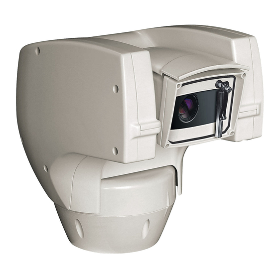
    Auf den Schwenk-Neige-Köpfen befindet sich ein Schildchen, das der CE- Bezeichnung des Produktes Kennzeichnung entspricht. ULISSE COMPACT ist eine robuste und effiziente PTZ-Kamera-Einheit, die entwickelt wurde, um eine dynamische Nonstop-Überwachung von großen Außenbereichen zu garantieren und beständig gegen schwierige Witterungsbedingungen zu sein, wobei die Instandhaltungseingriffe gleich Null sind.
  • Seite 259: Versionen

    5 Versionen 5.2 LED- Scheinwerfer Der Schwenk-Neige-Kopf kann mit einem LED- 5.1 Vorinstallierter Wischer Scheinwerfer versehen sein. Das Produkt kann mit einem Scheibenwischer ausgestattet sein. Abb. 4 Abb. 3 Für weitere Infos bitte entsprechendes Kapitel beachten (9.3.2 Benutzersteuerung, Für weitere Infos bitte entsprechendes Seite 47).
  • Seite 260: Vorbereitung Des Produktes Auf Den Gebrauch

    6 Vorbereitung des 6.2 Entfernen der Verpackung Produktes auf den Gebrauch Bei der Lieferung des Produktes ist zu prüfen, ob die Verpackung intakt ist oder offensichtliche Anzeichen von Stürzen oder Abrieb aufweist. Jede vom Hersteller nicht ausdrücklich genehmigte Veränderung führt zum Verfall Bei offensichtlichen Schadensspuren an der der Gewährleistungsrechte.
  • Seite 261: Auf Die Installation Vorbereitende Tätigkeiten

    7 Installation 6.5 Auf die Installation vorbereitende Tätigkeiten Unter keinen Umständen dürfen Veränderungen oder Anschlüsse 6.5.1 Befestigung der Halterung vorgenommen werden, die in diesem Verschiedene Halterungen sind (10 Zubehör, Seite  Handbuch nicht genannt sind. Die 54). Das geeignetste für die Installation auswählen Missachtung der Angaben, die das und alle Angaben aus diesem Kapitel befolgen.
  • Seite 262: Befestigung Der Basis An Der Halterung

    7.2 Befestigung der Basis an der 7.3 Anschluss der Halterung Verbinderplatine 7.3.1 Beschreibung der Karte Verwenden Sie die mit der Basis gelieferten Anschlüsse Schrauben und Unterlegscheiben. Nach der Positionierung der Dichtung (01) muss BESCHREIBUNG DER KARTE die Basis (02) auf der Halterung (03) befestigt Verbinder Funktion werden.
  • Seite 263: Anschluss Der Stromversorgung

    7.3.2 Anschluss der Stromversorgung Die Versorgungskabel sind der J2 Klemme nach der Tabelle anzuschließen. Die elektrischen Anschlüsse nur ANSCHLUSS DER STROMVERSORGUNG durchführen, wenn die Stromversorgung Farbe Klemmen abgetrennt und die Trennvorrichtung offen ist. Netzteil 24Vac Vom Installateur festgelegt. N (Nullleiter) Im Zuge der Installation ist zu prüfen, Vom Installateur festgelegt.
  • Seite 264: Anschluss Der Signalkabel

    7.3.3 Anschluss der Signalkabel. 7.3.3.2 Anschluss der Telemetrieleitungen Die Anlage gehört zum Typ CDS (Cable Alle Signalkabel mit einem Kabelbinder Distribution System). Nicht an Kreisläufe müssen zusammengefasst werden. SELV anschließen. ACHTUNG! Zur Senkung der Brandgefahr dürfen nur Kabel benutzt werden, die mindestens dem Schnitt 0.13mm²...
  • Seite 265: Anschluss Der Sekundären Steckerkarte

    7.4 Anschluss der sekundären 7.4.2 Anschluss der Alarmeingänge Steckerkarte Im Falle von Alarm mit potentialfreiem Kontakt muss der Anschluss gemäß der Abb. durchgeführt werden. Alle Signalkabel mit einem Kabelbinder Die Kontakte der Alarme befinden sich am Verbinder müssen zusammengefasst werden. (J4-J5).
  • Seite 266: Anschluss Der Relais

    7.4.3 Anschluss der Relais 7.4.4 Anschluss des Dämmerungsschalters für LED- Die Relais können nur für niedrige Scheinwerfer Betriebsspannungen (bis zu 30Vac oder 60Vdc) verwendet werden und mit einem Während der Installationstätigkeiten nicht Höchststrom von 1A. Kabel mit einem direkt in den leuchtenden Strahler schauen. für die Last geeignetem Querschnitt verwenden, und zwar zwischen einem Der Sensor muss richtig eingestellt werden,...
  • Seite 267: Anschluss Der Waschanlage

    7.4.6 Anschluss der Ethernet-Netz-Kabel Der Einsatz eines Dämmerungsschalters ist vorteilhaft in Zonen mit großen Dieses Funktionsmodus ist nur bei IP- Helligkeitsunterschieden. Version gültig. Wenn der Scheinwerfer angeht, Die Übertragung der Telemetrie und des wechselt die Kamera automatisch in den Videosignals erfolgt über das Ethernet- Nachtmodus.
  • Seite 268: Befestigung Des Oberen Körpers

    7.5 Befestigung des oberen 7.6 Hardware Konfiguration Körpers 7.6.1 Öffnen der Konfigurationsklappe Den selbstzentrierenden Steckverbinder (01) der Bevor die Einrichtung mit Strom versorgt wird, oberen Einheit ausrichten. Den seitlichen Überstand muss sie richtig mit den Dipschaltern innerhalb des (02) in die Blickrichtung der Videokamera ausrichten. Konfigurierungskläppchens konfiguriert werden.
  • Seite 269: Vorgabe Des Einstellungsprüfmodus (Dip 1)

    7.6.3 Vorgabe des 7.6.5 Die Leitungen der seriellen Einstellungsprüfmodus (DIP 1) Datenübertragung konfigurieren Zur Festlegung der seriellen SW 1=ON: Anzeige Konfiguration. Nur verwenden, um die Konfiguration nach Vornahme der Übertragungsleitungen eingreifen auf DIP 1. Einstellungen zu prüfen. Während des normalen Das Produkt sieht folgenden serielle Betriebes ist sicherzustellen, dass der kleine Hebel auf Datenaustauschlinien vor:...
  • Seite 270: Leitung Rs-485 Tx/Rx Bidirektional

    7.6.5.1 Leitung RS-485 TX/RX bidirektional 7.6.5.3 Leitung RS-422 bidirektional Diese Einstellung gestattet eine beidseitig gerichtete Diese Einstellung gestattet die Full-Duplex- Half-Duplex-Übertragung auf der Leitung RS-485-1. Kommunikation nach dem Standard RS-422. Die serielle Leitung RS-485-2 ist nicht benutzt. La ligne RS-485-1 est toujours en réception (RS-422- RX).
  • Seite 271: Abschließens Serieller Leitungen

    KONFIGURATION DES PROTOKOLL (DIP 3) Deformationen auftreten. SW 1 SW 2 SW 3 SW 4 Konfiguration ABSCHLIESSENS SERIELLER LEITUNGEN (DIP 1) AMERICAN DYNAMICS ERNITEC NETWORK PANASONIC PELCO D VIDEOTEC MACRO Tab. 10 Abschließens – – ON Linie RS-485-2, Abschluss 7.6.8 Adressekonfiguration serieller aktiviert Leitungen Zur Festlegung der Adresse eingreifen auf DIP 2.
  • Seite 272: Einschaltung

    8 Einschaltung 8.2 Liste der Kontrollen Wenn eine der Kontrollen den Test (ERR) Der automatische Vorheizvorgang (De-Ice) nicht besteht, kontaktieren Sie den könnte immer dann aktiviert werden, wenn technischen Kundendienst. “- -“ bedeutet, das Gerät bei einer Umgebungstemperatur dass der Schwenk-Neige-Kopf nicht mit der von unter 0°C in Betrieb genommen wird.
  • Seite 273: Konfiguration

    9 Konfiguration 9.1.1.1 Verwendung des Steuerknüppels Alle Menüvorgänge werden mit dem Steuerknüppel Die Konfiguration des Geräts kann unter Verwendung veranlasst. folgender Instrumente erfolgen: • OSM-Schnittstelle (On Screen Menu): Konfiguration mittels Text auf analogem Videosignal. • Software-Schnittstelle: Konfiguration mittels auf PC installierter Anwendung. Links Rechts •...
  • Seite 274: Das Bewegen Innerhalb Der Menüs

    9.1.2 Das Bewegen innerhalb der Menüs 9.1.3 Ändern von Parametern Jeder OSM-Bildschirm weist eine Liste mit Parametern Den Cursor auf den zu ändernden Parameter oder Untermenüs auf, die vom Bediener angewählt bewegen und bestätigen. Das Feld beginnt zu werden können. Um die verschiedenen Parameter blinken als Zeichen dafür, dass es geändert wird.
  • Seite 275: Ändern Der Zahlenfelder

    9.1.4 Ändern der Zahlenfelder 9.1.5 Ändern von Texten Den Cursor auf den zu ändernden Parameter Den Cursor auf den zu ändernden Parameter bewegen und bestätigen. bewegen und bestätigen. PRESET ANDERN ZONE ANDERN ------------------------ ------------------------ 1 NR. 1 NR 2 ABIL.: 2 START:+ 0.00 3>PAN...
  • Seite 276 Es ist möglich, mit dem Joystick innerhalb des Menüs Verwenden Sie: zu navigieren. • ERASE: Die gesamte Textzeichenfolge löschen. • SAVE: Speichern des neuen Textes vor dem Austritt EDIT TEXT: AREA aus dem Menü. ------------------------ • EXIT: Austritt aus dem Menü. Text: TEXT AREA1 ↑...
  • Seite 277: Konfiguration Über Osm

    9.1.6 Konfiguration über OSM 9.1.9 Kameramenü Im Folgenden werden die Bildschirmseiten zur Konfiguration: Hier kann eine der für das Modul Konfiguration des Produkts beschrieben. SONY vorgegebenen Konfigurationen gewählt werden: 9.1.7 Hauptmenü • Standard: Normaler Kamerabetrieb. Vom Hauptmenü aus kann die Konfigurierung der •...
  • Seite 278: Menü Zonenbetitelung

    9.1.9.1 Menü Zonenbetitelung Beispiel: Um die Betitelung der Zone 1 zu aktivieren, wenn sich die Vorrichtung zwischen +15° und +45° Diese Funktion gestattet die Festlegung von bis zu befindet, ist folgendermaßen vorzugehen: acht Zonen (verschiedener Größe), die sich betiteln • Die Zonenbetitelung aktivieren, indem man lassen.
  • Seite 279: Menü Maskierung

    9.1.9.3 Menü Maskierung 9.1.9.4 Menü Maskierung (Masken Ändern) Die dynamische Maskierung ermöglicht die Vorgabe Ermöglicht die Konfiguration folgender Parameter: von bis zu 24 Masken, mit denen besondere Maskennummer: Zur Auswahl der zu benutzerdefinierte Bereiche verdunkelt werden. ändernden Maske. Die Masken werden im Raum definiert und Maske Aktivieren: Aktiviert oder deaktiviert die berücksichtigen die Zoomposition in der ausgewählte Maske.
  • Seite 280: Ptz Bewegung On

    • Mit dem Steuerknüppel der Bedientastatur die • Es erscheint ein kleines Rechteck. Mit dem Einheit bewegen und bei Bedarf zoomen, bis die Steuerknüppel (Pan und Tilt) das Rechteck Blume auf dem Bildschirm zentriert ist. vergrößern, bis die gesamte Blume verdeckt ist. MASK 1 MASK 1 PTZ Bewegung ON...
  • Seite 281: Menü Erweitert Konfiguriert

    9.1.9.7 Menü Erweitert Konfiguriert 9.1.9.9 Menü Erweitert Konfiguriert (Focus) Mit diesem Menü kann das Modul von SONY Ermöglicht die Konfiguration folgender Parameter: konfiguriert werden. Focus-Geschwindigkeit: Einstellbar Zoom: Aufruf des Untermenüs Zoom. ist hier die Focusgeschwindigkeit. Die Geschwindigkeitswerte liegen in einem Bereich zwischen 0 (Mindestgeschwindigkeit) und 7 ERWEITERTE (Höchstgeschwindigkeit).
  • Seite 282: Menü Erweitert Konfiguriert (Belichtung)

    9.1.9.10 Menü Erweitert Konfiguriert In der folgenden Tabelle sind die Entsprechungen zwischen den eingegebenen Werten und (Belichtung) der Wirkung auf die Optik des SONY-Moduls Ermöglicht die Konfiguration folgender Parameter: zusammengestellt. 1-5. Modus: Art der Belichtungssteuerung - ENTSPRECHUNG WERT/WIRCHUNG FÜR DIE OPTIK Automatik, Manuell, Shutter, Iris und Bright.
  • Seite 283: Menü Erweitert Konfiguriert (Infrarot)

    9.1.9.11 Menü Erweitert Konfiguriert Um falsche Schaltungen zu vermeiden ist (Infrarot) es ratsam, die höchsten Werte sowohl für Ermöglicht die Konfiguration folgender Parameter: die Schwelle als auch die Verzögerung der Tagschaltung auszuwählen. IR-Modus: Wird hier OFF eingestellt, ist dauerhaft der Tagesmodus aktiviert (ein vorhandener Scheinwerfer wird mit INFRAROT Dämmerungsschalter oder dem zugehörigen...
  • Seite 284: Menü Erweitert Konfiguriert (Weißabgleich)

    9.1.9.12 Menü Erweitert Konfiguriert (Weiß 9.1.9.13 Menü Erweitert Konfiguriert abgleich) (Anderen) Ermöglicht die Konfiguration folgender Parameter: Sharfe: Einstellung der Bildschärfe. Modus: Einstellbar ist die Steuerung des Hohe Auflosung: Zum Einschalten der Funktion Weißabgleichs. Folgende Werte sind möglich: Hohe Auflosung. Das ausgehende Videosignal hat eine höhere Auflösung.
  • Seite 285: Menü Bewegung

    9.1.10 Menü Bewegung 9.1.10.1 Menü Handsteuerung Höchstgeschwindigkeit: Hier kann die Konfiguration: Eine der vorgegebenen Höchstgeschwindigkeit bei manueller Konfigurationen des Schwenk-Neige-Kopfes Steuerung vorgegeben werden.. kann eingestellt werden. Fastmodus: Zum Einschalten des Fastbetriebes. • Standard: Normale Wenn diese Option aktiviert wird, kann der Bewegungsgeschwindigkeit.
  • Seite 286: Menü Handsteuerung (Grenzpunkte)

    9.1.10.2 Menü Handsteuerung (Grenzpunk 9.1.10.4 Menü Preset (Preset Ändern) Ermöglicht die Konfiguration folgender Parameter: Ermöglicht die Konfiguration folgender Parameter: Nummer: Dies ist die Nummer des zu ändernden Preset. Grenzpunkte Pan: Aktiviert die Grenzpunkte für die Funktion Pan (Kameraschwenk). Befähigung: Zum Einschalten des Preset. Beginn Pan: Vorgabe der Grenzposition zu Pan: Pan-Position in Grad.
  • Seite 287: Menü Preset (Utility Preset)

    9.1.10.5 Menü Preset (Utility Preset) 9.1.10.6 Menü Patrol Ermöglicht die Konfiguration folgender Parameter: Erstes Preset: Erster Preset der Sequenz Patrol. A.Focus Tag: Zum Einschalten des Autofokus Letzes Preset: Letzter Preset der Sequenz Patrol. beim Aufruf der Presets im Tagesmodus. Damit Random Modus: Aktiviert wird die zufällige eine schnelle und saubere Fokussierung des Ausführung.
  • Seite 288: Menü Bewegungsanforderung

    9.1.10.8 Menü Bewegungsanforderung 9.1.10.9 Menü Erweiterte Das Gerät kann so konfiguriert werden, dass nach Statische Steuerung: Aktiviert die einer gewissen Zeit der Inaktivität automatisch eine Positionssteuerung nur, wenn die Schwenk- vom Bediener ausgewählte Bewegungsfunktion Neige-Einrichtung stillsteht. ausgeführt wird. Dynamische Steuerung: Aktiviert die Bewegungsart: Auswahl der aufzurufenden Positionssteuerung nur, wenn die Schwenk- Bewegungsart (None, Home, Autopan, Patrol,...
  • Seite 289: Menü Anzeigen

    9.1.11 Menü Anzeigen Delta Vertical: Bewegt die Menütexte zur besseren Textzentrierung vertikal. Position PTZ: Wenn die Einstellung nicht auf OFF lautet, kann gewählt werden, wie auf dem ANZEIGEN Bildschirm die Positionen Pan, Tilt und Zoom ------------------------ angezeigt werden. Es kann eine bestimmte 1>POSITION PTZ Anzeigedauer (1 S, 3 S und 5 S) oder eine 2 NAME PRESET...
  • Seite 290: Menü Alarme

    9.1.12.1 Menü Alarme Vom Menü Alarme kann man auf eines der Menüs (Alarm 1-5) zugreifen und dort die Alarmparameter 1-5. Alarm 1-5: Sie ermöglichen den Aufruf der ändern. Menüs, in denen die Parameter der Alarme 1 bis In diesem Menü können die folgenden Werte 5 festgelegt werden können.
  • Seite 291: Menü Waschanlage

    9.1.13 Menü Waschanlage 9.1.14 Menü Default Der S-N-Kopf bietet die Möglichkeit, einen Setup löschen?: Versetzt alle Parameter außer Scheibenwischer einzusetzen und eine Pumpe für die die Presetparameter in den ursprünglichen Scheibenreinigung zu betätigen. Zustand. Zur Einstellung der Waschanlage das Kameraobjektiv Preset löschen?: Löscht alle gespeicherten vor der Düse der Waschanlage positionieren.
  • Seite 292: Software-Schnittstelle

    9.2 Software-Schnittstelle Wenn der Login erfolgreich abgeschlossen wurde, wird die Steuer-Schnittstelle des Schwenk-Neige- 9.2.1 Mindestanforderungen an den PC Kopfs angezeigt. Die mitgelieferte Betriebssoftware des Schwenk- Neige-Kopfs unterstützt bis zu 16 Kanäle. Die Software erfordert Windows XP Service Pack 3 oder höher und einen PC mit einem Xeon-Prozessor mit 2,3GHz oder höher.
  • Seite 293 Die Taste Add. anklicken. Die Kamera steht in der Liste der Vorrichtungen (Camera list) zur Verfügung und kann mittels Drag and Drop des Symbols in eines der nicht verwendeten Felder angezeigt werden. Abb. 86 Abb. 88 Der Kamera und der Gruppe einen Namen zuweisen. Zur Anzeige der Kameras auf mehreren Computern Das ONVIF oder TCAM Protokoll wählen und die muss der TVM-Client installiert werden und über...
  • Seite 294: Web-Schnittstelle

    9.3 Web-Schnittstelle Ein Fenster wird angezeigt, in dem die Server hinzugefügt werden können, mit denen durch Drücken der Taste Add eine Verbindung hergestellt Beim ersten Anschluss eine Adresse werden kann. zuweisen, die nicht 192.168.10.100 ist. Unterstützte Browser: Microsoft Internet Explorer, Google Chrome, Mozilla Firefox. Der erste Schritt zur Konfiguration des S-N-Kopfes ist die Verbindung mit seiner Web-Schnittstelle.
  • Seite 295: Benutzersteuerung

    9.3.2 Benutzersteuerung • Focus far/Focus near/Auto focus Um den Schwenk-Neige-Kopf via Browser zu steuern, wählen Sie den Eintrag Benutzersteuerung. Es öffnet sich ein neues Fenster mit einer virtuellen Tastatur zum Absenden von Befehlen. Abb. 96 • Iris close/Iris open/Auto iris Abb.
  • Seite 296: Geräteparameter

    9.3.3 Geräteparameter 9.3.5 Netzwerk-Konfiguration Im Menü-Eintrag Geräteparameter können der Name Im Menü-Eintrag Netzwerk-Konfiguration kann die des Schwenk-Neige-Kopfes eingestellt und andere Netzwerk-Einstellung des Schwenk-Neige-Kopfes Zusatzinformationen angezeigt werden. geändert werden. Es kann eingestellt werden, ob das Gerät eine statisch oder dynamisch mit DHCP zugewiesene Adresse haben muss.
  • Seite 297: Benutzer-Konfiguration

    9.3.6 Benutzer-Konfiguration • Autoflip: Dreht den Schwenk-Neige-Kopf um 180°, wenn die Neigung des Schwenk-Neige-Kopfs den Im Menü-Eintrag Benutzer-Konfiguration können Endanschlag erreicht. Dadurch wird die Verfolgung die Benutzer verwaltet werden, die Zugriff auf den von Subjekten entlang von Fluren oder Straßen Schwenk-Neige-Kopf haben.
  • Seite 298: Autopan

    9.3.7.1 Autopan 9.3.7.3 Bewegungsanforderung Im Unterabschnitt Autopan können die Presets für Im Unterabschnitt Aufruf Bewegungen kann eine Beginn und Ende des Autopan angegeben werden. Inaktivitätsdauer angegeben werden, nach der der Schwenk-Neige-Kopf eine der folgenden Funktionen Es ist möglich, die Geschwindigkeit einzustellen, mit ausführt: Rückkehr in die Home-Position, Start des der die Strecke zurückgelegt werden soll.
  • Seite 299: Preset-Parameter

    9.3.8 Preset-Parameter 9.3.9 Preset-Parameter (Erweitert) Im Menü-Eintrag Preset-Parameter sind einige Im Abschnitt Preset-Parameter (Erweitert) können Parameter der Presets konfigurierbar: die Werte für Geschwindigkeit und Pause für jeden Preset individuell angepasst, sowie die Presets selbst • Scan Geschwindigkeit: Geschwindigkeit in Grad aktiviert/deaktiviert werden.
  • Seite 300: Digitale I/O

    9.3.10 Digitale I/O 9.3.11 Wiper In der Registerkarte Digitale I/O können die digitalen Der Scheibenwischer ist bei Kanäle des Schwenk-Neige-Kopfes konfiguriert Aussentemperaturen unter 0°C oder bei werden. Es folgt eine kurze Beschreibung der Glas nicht zu betätigen. konfigurierbaren Parameter für jeden Digitaleingang. Das Gehäuse ist mit dem vorinstallierten •...
  • Seite 301: Encodereinstellungen

    9.3.13 Encodereinstellungen 9.3.14 Werkzeuge Unter dem Menüpunkt Encodereinstellungen Im Menü-Eintrag Werkzeuge können die gesamte können die 12 Videoströme des Geräts konfiguriert Konfiguration des Schwenk-Neige-Kopfes oder nur werden. Der erste Strom wird zwangsläufig mit dem bestimmte Abschnitte auf die vordefinierten Werte Algorithmus H.264/AVC komprimiert, während der zurückgesetzt werden.
  • Seite 302: Zubehör

    10 Zubehör 10.3 Halterung für Brüstungsmontage Für weitere Details zur Konfiguration und zum Gebrauch beachten Sie bitte das Brüstunghalterung mit interner Kabelführung. Handbuch des entsprechenden Geräts. 10.1 Waschanlage Der Schwenk-Neige-Kopf muss mit einer externen Pumpe ausgestattet sein, die Wasser für die Reinigung des Glases liefert.
  • Seite 303: Anleitung Für Den Normalen Betrieb

    11 Anleitung für den 11.2 Speichern eines Preset. normalen Betrieb 11.2.1 Schnellspeicherung Mit der Bedientastatur kann die aktuelle Position 11.1 Statusanzeige Schwenk- gespeichert werden. Für weitere Informationen siehe Neige-Kopf das Handbuch der verwendeten Tastatur. Während des Speichervorgangs kann die Während des normalen Betriebes zeigt der Schwenk- Geschwindigkeit beim Anfahren des Preset mit den Neige-Kopf nach Wahl des Benutzers auf dem Tasten Focus Far/Focus Near sowie die Wartezeit mit...
  • Seite 304: Aufruf Einer Position Preset (Scan)

    11.3 Aufruf einer Position Preset 11.6 Aufruf einer Strecke (Tour) (Scan) Die Betriebsart Tour ermöglicht es, einen zuvor registrierten Streckenverlauf ständig abzufahren. Mithilfe des Kontrollgerätes kann eine zuvor Der Schwenk-Neige-Kopf kann bis zu 3 Tour von einer gespeicherte Preset Position aufgerufen werden maximalen Dauer von je 2 Minuten speichern.
  • Seite 305: Aufruf Der Homeposition

    11.7 Aufruf der Homeposition 11.10 Aktivierung des LED- Scheinwerfer Mithilfe des Kontrollgerätes kann eine zuvor gespeicherte Home (Scan n.1) Position aufgerufen Wenn die Anlage über keinen Dämmerungsschalter werden (für weitere Informationen siehe das verfügt, kann der LED- Scheinwerfer mit der Handbuch des verwendeten Kontrollgerätes).
  • Seite 306: Spezialbefehle

    DE - Deutsch - Bedienungslanleitung 11.13 Spezialbefehle SPEZIALBEFEHLE Befehl Protokoll VIDEOTEC MACRO AMERICAN DYNAMICS ERNITEC ONVIF (auxiliary PANASONIC PELCO D command) Tour 1 Start Aufnahme Preset Speichern 77 Preset Speichern 77 Preset Speichern 77 Preset Speichern 77 Preset Speichern 77...
  • Seite 307 SPEZIALBEFEHLE Befehl Protokoll VIDEOTEC MACRO AMERICAN DYNAMICS ERNITEC ONVIF (auxiliary PANASONIC PELCO D command) Wiper Start Preset Speichern 85 Preset Speichern 85 Preset Speichern 85 tt:Wiper|On Preset Speichern 85 Preset Speichern 85 Aux 3 ON Aux 3 ON Aux 3 ON...
  • Seite 308 DE - Deutsch - Bedienungslanleitung SPEZIALBEFEHLE Befehl Protokoll VIDEOTEC MACRO AMERICAN DYNAMICS ERNITEC ONVIF (auxiliary PANASONIC PELCO D command) Patrol Start Preset Speichern 93 Preset Speichern 93 Preset Speichern 93 tt:Patrol|On Preset Speichern 93 Preset Speichern 93 Pat+ Einschalten pattern 1...
  • Seite 309: Wartung Und Reinigung

    WECHSEL DER SICHERUNGEN Die Operation kann auch von fern (nur Protokolle Spannung Schmelz- siche- Schmelz- siche- VIDEOTEC MACRO und PELCO D) mit einem USB/ rung F1 rung F2 Seriellen 485 Wandler durchgeführt werden (nicht im 24Vac, 50/60Hz T 4A L 250V 5x20 T 6.3A H 250V...
  • Seite 310: Müllentsorgungsstellen

    13 Müllentsorgungsstellen 14 Problemlösung Fordern Sie Fachleute für die Arbeiten an, wenn: Dieses Symbol und das entsprechende • Die Einheit nach einem Sturz beschädigt ist; Recycling-System gelten nur für EULänder und finden in den anderen Ländern der • Die Leistungen der Einheit merklich abgefallen Welt keine Anwendung.
  • Seite 311 Auf dem Monitor wird das Die Umgebungstemperatur ist zu PROBLEM URSACHE aufgenommene Bild nicht niedrig. angezeigt, sondern ein LÖSUNG Ende des Vorheizvorgangs Bildschirm mit dem folgenden abwarten. Wenn die Umgebungs- Aussehen: temperatur zu niedrig ist, blockiert die Einheit und zeigt den folgenden Bildschirm: Adresse : 1 Protokoll : MACRO...
  • Seite 312 Fehler E2-SCHEIBENWISCHER Fehler E8-TOUR NICHT PROBLEM PROBLEM BLOCKIERT. KONFIGURIERT. Scheibenwischer blockiert oder Aufruf einer nicht programmierten URSACHE URSACHE defekt. Tour. LÖSUNG Sicherstellen, dass sich der LÖSUNG Die Tour mit dem zugehörigen Scheibenwischer ungehindert Befehl speichern (11.6 Aufruf einer bewegen kann. Strecke (Tour), Seite 56).
  • Seite 313: Technische Daten

    Neigung: Von -90° a +90° • PELCO D: 99* Schwenkgeschwindigkeit rechts - links (einstellbar): Von 0.1°/s a 200°/s • VIDEOTEC MACRO: 250 Neigegeschwindigkeit Auf-Ab einstellbar *250, nur von OSD (On Screen Display) (einstellbar): Von 0.1°/s a 200°/s 16-stellige Zeichenkette für die Betitelung der...
  • Seite 314: Protokolle

    AMERICAN DYNAMICS, ERNITEC, PANASONIC, PELCO sind eingetragene Markenzeichen. Die Einheit kann über Schnittstellen mit Produkten verbunden werden, die nicht von VIDEOTEC produziert sind. Es ist möglich, dass die Protokolle sich geändert haben oder die in einer anderen Konfiguration von früher von VIDEOTEC getesteten Einheiten sind.
  • Seite 315: Technische Zeichnungen

    16 Technische Zeichnungen Die Abmessungen der Zeichnungen sind in Millimeter angegeben. Abb. 123 ULISSE COMPACT. MNVCUCZ_1511_DE...
  • Seite 316 Abb. 124 ULISSE COMPACT mit LED Scheinwerfer. MNVCUCZ_1511_DE...
  • Seite 317: A Anhang - Adressentabelle

    A Anhang - Adressentabelle Der nach oben zeigende Kipphebel des Schalters steht für den Wert 1 (ON). Der nach unten zeigende Kipphebel des Dipschalters steht für den Wert 0 (OFF). Nachstehend sind alle Kombinationsmöglichkeiten aufgelistet. ADRESSEKONFIGURATION (DIP 2) SW 1 SW 2 SW 3 SW 4...
  • Seite 318 ADRESSEKONFIGURATION (DIP 2) SW 1 SW 2 SW 3 SW 4 SW 5 SW 6 SW 7 SW 8 SW 9 SW 10 (OFF) SW 10 (ON) Adresse 39 Adresse 551 Adresse 40 Adresse 552 Adresse 41 Adresse 553 Adresse 42 Adresse 554 Adresse 43 Adresse 555...
  • Seite 319 ADRESSEKONFIGURATION (DIP 2) SW 1 SW 2 SW 3 SW 4 SW 5 SW 6 SW 7 SW 8 SW 9 SW 10 (OFF) SW 10 (ON) Adresse 84 Adresse 596 Adresse 85 Adresse 597 Adresse 86 Adresse 598 Adresse 87 Adresse 599 Adresse 88 Adresse 600...
  • Seite 320 ADRESSEKONFIGURATION (DIP 2) SW 1 SW 2 SW 3 SW 4 SW 5 SW 6 SW 7 SW 8 SW 9 SW 10 (OFF) SW 10 (ON) Adresse 129 Adresse 641 Adresse 130 Adresse 642 Adresse 131 Adresse 643 Adresse 132 Adresse 644 Adresse 133 Adresse 645...
  • Seite 321 ADRESSEKONFIGURATION (DIP 2) SW 1 SW 2 SW 3 SW 4 SW 5 SW 6 SW 7 SW 8 SW 9 SW 10 (OFF) SW 10 (ON) Adresse 174 Adresse 686 Adresse 175 Adresse 687 Adresse 176 Adresse 688 Adresse 177 Adresse 689 Adresse 178 Adresse 690...
  • Seite 322 ADRESSEKONFIGURATION (DIP 2) SW 1 SW 2 SW 3 SW 4 SW 5 SW 6 SW 7 SW 8 SW 9 SW 10 (OFF) SW 10 (ON) Adresse 219 Adresse 731 Adresse 220 Adresse 732 Adresse 221 Adresse 733 Adresse 222 Adresse 734 Adresse 223 Adresse 735...
  • Seite 323 ADRESSEKONFIGURATION (DIP 2) SW 1 SW 2 SW 3 SW 4 SW 5 SW 6 SW 7 SW 8 SW 9 SW 10 (OFF) SW 10 (ON) Adresse 264 Adresse 776 Adresse 265 Adresse 777 Adresse 266 Adresse 778 Adresse 267 Adresse 779 Adresse 268 Adresse 780...
  • Seite 324 ADRESSEKONFIGURATION (DIP 2) SW 1 SW 2 SW 3 SW 4 SW 5 SW 6 SW 7 SW 8 SW 9 SW 10 (OFF) SW 10 (ON) Adresse 309 Adresse 821 Adresse 310 Adresse 822 Adresse 311 Adresse 823 Adresse 312 Adresse 824 Adresse 313 Adresse 825...
  • Seite 325 ADRESSEKONFIGURATION (DIP 2) SW 1 SW 2 SW 3 SW 4 SW 5 SW 6 SW 7 SW 8 SW 9 SW 10 (OFF) SW 10 (ON) Adresse 354 Adresse 866 Adresse 355 Adresse 867 Adresse 356 Adresse 868 Adresse 357 Adresse 869 Adresse 358 Adresse 870...
  • Seite 326 ADRESSEKONFIGURATION (DIP 2) SW 1 SW 2 SW 3 SW 4 SW 5 SW 6 SW 7 SW 8 SW 9 SW 10 (OFF) SW 10 (ON) Adresse 399 Adresse 911 Adresse 400 Adresse 912 Adresse 401 Adresse 913 Adresse 402 Adresse 914 Adresse 403 Adresse 915...
  • Seite 327 ADRESSEKONFIGURATION (DIP 2) SW 1 SW 2 SW 3 SW 4 SW 5 SW 6 SW 7 SW 8 SW 9 SW 10 (OFF) SW 10 (ON) Adresse 444 Adresse 956 Adresse 445 Adresse 957 Adresse 446 Adresse 958 Adresse 447 Adresse 959 Adresse 448 Adresse 960...
  • Seite 328 ADRESSEKONFIGURATION (DIP 2) SW 1 SW 2 SW 3 SW 4 SW 5 SW 6 SW 7 SW 8 SW 9 SW 10 (OFF) SW 10 (ON) Adresse 489 Adresse 1001 Adresse 490 Adresse 1002 Adresse 491 Adresse 1003 Adresse 492 Adresse 1004 Adresse 493 Adresse 1005...
  • Seite 330 Email: info@videotec.com Tel. +33 1 60491816 - Fax +33 1 69284736 Email: info.fr@videotec.com Asia Pacific Videotec (HK) Ltd Americas Videotec Security, Inc. Flat 8, 19/F. On Dak Industrial Building, No. 2-6 Wah Sing Street Gateway Industrial Park, 35 Gateway Drive, Suite 100 Kwai Chung, New Territories - Hong Kong Plattsburgh, NY 12901 - U.S.A.
  • Seite 331 ULISSE COMPACT Телекамера PTZ для внешнего наблюдения, гарантирующая максимальную точность наблюдения в режиме День/Ночь Русский - Руководство по эксплуатации...
  • Seite 333 Индекс РУССКИЙ 1 Информация о настоящем руководстве .................. 7 1.1 Типографские обозначения ..............................7 2 Примечания по авторскому праву и торговым маркам ............7 3 Правила безопасности ........................ 7 4 Идентификация ..........................10 4.1 Описание и назначение изделия ............................10 4.2 Маркировка изделия ................................10 4.2.1 Контроль...
  • Seite 334 7.6.5 Конфигурация cерийные линии связи ..............................21 7.6.5.1 Двунаправленная линия RS-485 TX/RX ..................................22 7.6.5.2 Линия RS-485-1 приёма, линия RS-485-2 ретрансляции ........................... 22 7.6.5.3 Двунаправленная линия RS-422....................................22 7.6.5.4 Однонаправленная линия RS-485 ....................................22 7.6.6 Вывод последовательных линий................................23 7.6.7 Установка протокола ....................................23 7.6.8 Установка...
  • Seite 335 9.1.15 Меню информации ....................................43 9.2 Интерфейс программного обеспечения ........................44 9.2.1 Минимальные реквизиты ПК .................................44 9.2.2 Процедура конфигурации с помощью программного обеспечения ..................44 9.2.3 Установка программного обеспечения ............................44 9.3 Интерфейс веб ....................................46 9.3.1 Home ..........................................46 9.3.2 Проверки пользователя ...................................47 9.3.3 Параметры Устройства .....................................48 9.3.4 Статистика...
  • Seite 336 12.1.1 Обновление микропрограммы ................................61 12.1.2 Копирование конфигурации ................................61 12.1.3 Замена предохранители ..................................61 12.2 Уборка ......................................61 12.2.1 Очистка стекла и пластмассовых частей ............................61 13 Вывоз в отходы ........................62 14 Устранение неисправностей ....................62 15 Технические параметры ......................65 15.1 Общее ......................................65 15.2 Механика ....................................65 15.3 Электрический/Видео...
  • Seite 337: Информация О Настоящем Руководстве

    1 Информация о настоящем 3 Правила безопасности руководстве LED инфракрасное излучение Не смотрите прямо на осветитель, используя оптические Перед монтажом и использованием настоящего блока, инструменты. Класс 1M LED устройства. внимательно прочитать настоящее руководство. Излучение оптической мощности в 0,1m: Хранить данное руководство под рукой для будущих 2.2mW @ 875nm, в...
  • Seite 338 • Это устройство предназначено для постоянно ПРЕДУПРЕЖДЕНИЕ! Установка типа TNV-1. Не действующей установки на здании или на подключайте к системам SELV. соответствующей конструкции. Устройство должно быть установлено на постоянной основе перед ПРЕДУПРЕЖДЕНИЕ! Во избежание выполнением любой операции. пожароопасности, заменяйте плавкие •...
  • Seite 339 • Подключите устройство к источнику питания, • Техобслуживание прибора должно выполняться который соответствует маркировке. Прежде чем только квалифицированным персоналом. Во приступить к установке, убедитесь, что линия время техобслуживания оператор подвержен электропередачи правильно секционирована. риску поражения электрическим током и другим Напряжение питания не должно превышать опасностям.
  • Seite 340: Идентификация

    4.2 Маркировка изделия 4.1 Описание и назначение На поворотные устройства наклеены этикетки, соответствующие маркировке ЕС. изделия ULISSE COMPACT - надежная и эффективная камера с увеличительным объективом (Pan/Tilt/Zoom), разработанная для обеспечения беспрерывного динамического наблюдения за внешними участками, хорошо выдерживает действие сложных атмосферных...
  • Seite 341: Версии

    5 Версии 5.2 Прожектор со LED Поворотное устройство может быть оснащено 5.1 Встроенная щетка очиститель светодиодным (LED) осветителем. Устройство может быть оснащено очистителем стекла. Рис. 4 Рис. 3 За дополнительной информацией обратитесь За дополнительной информацией обратитесь к соответствующей главе (9.3.2 Проверки к...
  • Seite 342: Подготовка Изделия К Использованию

    6 Подготовка изделия к 6.2 Распаковка использованию При поставке изделия убедитесь в том, что упаковка не повреждена и не имеет явных признаков падений или царапин. Любое изменение, выполненное без разрешения изготовителя, ведёт к потери В случае видимых повреждений упаковки немедленно гарантии.
  • Seite 343: Подготовительная Работа Перед Установкой

    7 Монтаж 6.5 Подготовительная работа перед установкой Ни в коем случае не вносить изменений и не выполнять подключений, не 6.5.1 Установка кронштейна предусмотренных данным руководством. В наличии разные типы кронштейнов (10 Несоблюдение инструкций, предоставленных Аксессуары, страница 54). Выберите наиболее в руководстве и касающихся соединений, подходящий...
  • Seite 344: Прикрепление Основания К Кронштейну

    7.2 Прикрепление основания к 7.3 Подключение платы разъемов кронштейну 7.3.1 Описание платы разъемов ОПИСАНИЕ ПЛАТЫ Используйте винты и шайбы, поставляемые с основанием. Разъём Функция Линии питания После установки уплотнителя (01) прикрепите J5/J7 Выход видео основание (02) кронштейна (03), используя винты (04), зубчатые...
  • Seite 345: Подключение К Линии Питания

    7.3.2 Подключение к линии питания Подключите кабели питания к клемме J2 , как описано в таблице. Выполнять электрические подключения ПОДКЛЮЧЕНИЕ К ЛИНИИ ПИТАНИЯ при отсутствии питания и с открытым Цвет Клеммы разъединяющим устройством. Источник питания 24Vac В момент монтажа убедитесь в том, что Определяется...
  • Seite 346: Подключение Сигнальных Кабелей

    7.3.3 Подключение сигнальных кабелей 7.3.3.2 Подключение к линии телеметрирования Все сигнальные кабели должны быть сгруппированы под одним хомутиком. Установка типа кабельного телевидения CDS (Cable Distribution System). Не подключайте к системам SELV. ПРЕДУПРЕЖДЕНИЕ! Для снижения опасности пожара пользуйтесь исключительно кабелями, имеющими разделы одинаковые или...
  • Seite 347: Подключение Вспомогательной Платы Разъемов

    7.4 Подключение вспомогательной 7.4.2 Подключение входов сигналов тревог платы разъемов В случае сигнала тревоги на свободном контакте выполните подключение, как показано на рисунке Все сигнальные кабели должны быть сгруппированы под одним хомутиком. Контакты сигналов тревоги присутствуют на разъёме (J4-J5). 7.4.1 Описание вспомогательной платы Cухой...
  • Seite 348: Подключения Реле

    7.4.3 Подключения реле 7.4.4 Подключение сумеречного выключателя для светодиодного (LED) Реле используются только для низкого осветителя рабочего напряжения (до 30Vac или 60Vdc) при максимальной силе тока 1A. Во время проведения операций по установке Использовать кабели с подходящей сечением не смотрите прямо на включенный для...
  • Seite 349: Подключение Моющего Оборудования

    7.4.6 Подключение кабеля к сети Ethernet Использование сумеречного выключателя имеет преимущества при наличии Подключение действительно только для больших участков с большими перепадами версии с платой IP. освещенности. Передача телеметрирования и видео- Когда прожектор включается, телекамера сигнала производятся посредством кабеля автоматически переходит на ночной режим сети...
  • Seite 350: Крепление Верхнего Корпуса

    7.5 Крепление верхнего корпуса 7.6 Конфигурация аппаратного обеспечения Направьте самоцентрирующийся разъем (01) верхнего узла. Направьте боковой выступ (02) в направлении 7.6.1 Открытие конфигурационной переднего поля зрения телекамеры. Расположите дверцы верхний узел на основании, ориентируя как показано на рисунке. Перед подачей питания на устройство, необходимо правильно...
  • Seite 351: Установка Режима Проверки Настроек (Dip 1)

    7.6.3 Установка режима проверки 7.6.5 Конфигурация cерийные линии настроек (DIP 1) связи Для установки и определения серийных линий SW 1=ON: Отображает конфигурацию. Используется только для проверки конфигурации в конце настроек. сообщений необходимо пользоваться DIP 1. Во время нормального использования убедитесь в том, Продукт...
  • Seite 352: Двунаправленная Линия Rs-485 Tx/Rx

    7.6.5.1 Двунаправленная линия RS-485 TX/RX 7.6.5.3 Двунаправленная линия RS-422 Этот установки позволяет получить двунаправленное Эта установка позволяет сообщение в дуплексной связи сообщение полудуплексной связи (half-duplex) на линии (full duplex) в соответствии со стандартом RS-422. RS-485-1. Линия RS-485-1 всегда в режиме приёма (RS-422-RX). Серийная...
  • Seite 353: Вывод Последовательных Линий

    УСТАНОВКА ПРОТОКОЛА (DIP 3) SW 1 SW 2 SW 3 SW 4 Конфигурация ВЫВОД ПОСЛЕДОВАТЕЛЬНЫХ ЛИНИЙ (DIP 1) AMERICAN DYNAMICS ERNITEC NETWORK PANASONIC PELCO D VIDEOTEC MACRO Вывод – – Линия RS-485-2, вывод Таб. 10 последовательных подключён 7.6.8 Установка адреса линий – –...
  • Seite 354: Включение

    8 Включение 8.2 Список проверок Если одна из проверок не проходит тест (ERR), Процедура автоматического свяжитесь с центром технической поддержки. предварительного подогрева (De-Ice) Надпись "--" означает, что описанная опция в может быть активирована всегда, когда поворотном устройстве отсутствует. устройство включается при температуре окружающей...
  • Seite 355: Конфигурация

    9 Конфигурация 9.1.1.1 Как пользоваться джойстиком Все операции меню выполняются с использованием Конфигурация прибора может выполнятся с джойстика. использованием одного из следующих инструментов: Высоко • Интерфейс OSM (On Screen Menu (Меню н экране)): Конфигурация с помощью текста на аналоговом видеосигнале •...
  • Seite 356: Как Двигаться По Меню

    9.1.2 Как двигаться по меню 9.1.3 Как изменить параметры Каждая рабочая область OSM представляет список Сместите курсор в соответствии с параметром, который параметров или подменю, которые могут быть желаете изменить, и подтвердите. Поле начнёт мигать, выбраны оператором. Для пролистывания различных указывая, что...
  • Seite 357: Как Изменить Цифровые Поля

    9.1.4 Как изменить цифровые поля 9.1.5 Как изменить тексты Сместите курсор в соответствии с параметром, который Сместите курсор в соответствии с параметром, который желаете изменить, и подтвердите. желаете изменить, и подтвердите. EDIT PRESET EDIT ZONE ------------------------ ------------------------ 1 NR. 1 NR 2 ON 2 START:+ 0.00...
  • Seite 358 Можно перемещаться по меню при помощи джойстика. Использовать: • ERASE: Удаление целой строки текста. EDIT TEXT: AREA • SAVE: Сохраните новый текст перед выходом из ------------------------ меню. Text: TEXT AREA1 • EXIT: Выход из меню. ↑ A B C D E F G ERASE •...
  • Seite 359: Конфигурации Посредством Osm

    9.1.6 Конфигурации посредством OSM 9.1.9 Меню телекамеры Ниже будут показаны экранные изображения, Конфигурация: Устанавливает необходимые для конфигурации изделия. конфигурации, предусмотренные для модуля SONY: 9.1.7 Главное меню • Standard: Устанавливает стандартный режим В главном меню можно получить доступ к конфигурации работы телекамеры. устройства.
  • Seite 360: Меню Титрования Зон

    9.1.9.1 Меню Титрования зон Пример: Для активации титрование зоны 1, когда устройство находится между +15° и +45°, необходимо: Эта функция позволяет установить до восьми зон • Включает титрование зон, устанавливая S в качестве (различных размеров) с возможностью титрирования. значения позиции Включение меню титрования зон. Включение: Включает...
  • Seite 361: Меню Каширования

    9.1.9.3 Меню каширования 9.1.9.4 Меню каширования (Изменяет Маски) Динамическое каширование позволяет создавать Позволяет настроить следующие параметры: максимум до 24 масок таким образом, чтобы Маска Номер: Позволяет выбор маски для получить потемнения определённых зон, выбранных работы. пользователем. Подготавливает маскирование: Включает Маски будут определяться в пространстве и будут или...
  • Seite 362: Как Изменить Маску

    • Нажатием на джойстик клавиатуры прибор • Появится небольшой прямоугольник. Нажав на передвинуть прибор и при необходимости джойстик (Pan и Tilt) увеличивается прямоугольник установить зум до появления цветка в центре экрана. до тех пор, как не покроется весь цветок. MASK 1 MASK 1 PTZ Motions Enabled Edit Mask: ON...
  • Seite 363: Меню Дополнительных Конфигураций

    9.1.9.7 Меню дополнительных конфигураций 9.1.9.9 Меню дополнительных конфигураций (Focus) Получая доступ к этому меню, можно произвести конфигурацию модуля SONY. Позволяет настроить следующие параметры: Zoom: Позволяет получать доступ к подменю Скорость Фокусировки: Устанавливает Зума. скорость фокусировки. Значения скорости - от 0 (минимальная скорость) до 7 (максимальная...
  • Seite 364: Меню Дополнительных Конфигураций (Воздействие)

    9.1.9.10 Меню дополнительных конфигураций В следующей таблице приводятся соответствия между введёнными величинами и оптическим действием (Воздействие) модуля SONY. Позволяет настроить следующие параметры: ОПТИЧЕСКОЕ СООТВЕТСТВИЕ ЗНАЧЕНИЯ/ДЕЙСТВИЯ 1-5. Режим: Устанавливает тип контроля МОДУЛЯ SONY выдерживания: автоматический, ручной, Shutter, Iris и Bright. Auto Slowshutter: Если включена, увеличивает...
  • Seite 365: Меню Дополнительных Конфигураций (Инфракрасный)

    9.1.9.11 Меню дополнительных конфигураций Во избежание ошибочных сообщений (Инфракрасный) рекомендуется выбирать величины порога Позволяет настроить следующие параметры: и более серьёзные ошибки дневных переключений. Режим IR: Если выполнены настройки OFF, они форсируют дневной режим непрерывно (освещение фарой, если выполняется INFRARED посредством специального обжатого ------------------------ переключателя...
  • Seite 366: Меню Дополнительных Конфигураций (Баланс Белого Цвета)

    9.1.9.12 Меню дополнительных конфигураций 9.1.9.13 Меню дополнительных конфигураций (Баланс Белого Цвета) (Другое) Позволяет настроить следующие параметры: Резкость: Устанавливает значение резкости изображения. Режим: Устанавливает тип контроля баланса Высокое разрешение: Подготавливает белого цвета. Возможные значения: высокое разрешение. Выходной сигнал видео • Автоматически: автоматически устанавливает имеет...
  • Seite 367: Меню Движения

    9.1.10 Меню движения 9.1.10.1 Меню ручного контроля Максимальная Скорость: Устанавливает Конфигурация: Устанавливает вручную максимальную скорость. конфигурации, предусмотренные наводкой. Режим Fast: Активирует режим Fast. Эта • Standard: Устанавливает стандартную скорость опция, если она включена, позволяет быстро движений. перемещать наводку при помощи джойстика Offset Pan: Наводка...
  • Seite 368: Меню Ручного Контроля (Рамки)

    9.1.10.2 Меню ручного контроля (Рамки) 9.1.10.4 Меню Preset (Изменяет Preset) Позволяет настроить следующие параметры: Позволяет настроить следующие параметры: Ограничения Pan: Подготавливает Число: Номер Preset, который желаете ограничения Pan. изменить. Начало Pan: Устанавливает начальное Включение: Включение preset. ограничение Pan. Pan: Положение pan, выраженное в градусах. Окончание...
  • Seite 369: Меню Preset (Служебная Программа Preset)

    9.1.10.5 Меню Preset (Служебная Программа 9.1.10.6 Меню патрулирования (Patrol) Preset) Первый Preset: Первый preset последовательности Patrol. Позволяет настроить следующие параметры: Последний Preset: Последний preset A.Дневная фокусировка: Позволяет последовательности Patrol. использовать автофокусировку во время вызова preset в дневном режиме. Для Режим Random: Подготавливает выполнение обеспечения...
  • Seite 370: Меню Вызова Движений

    9.1.10.8 Меню вызова движений 9.1.10.9 Дополнительные меню Можно настроить узел таким образом, что после Статический контроль: Подготавливает определенного периода простоя автоматически контроль положения только тогда, когда выполняется функция движения, установленная наводка остановлена. оператором. Динамический контроль: Подготавливает Вид Движения: Типа движения для вызова контроль...
  • Seite 371: Меню Визуализаций

    9.1.11 Меню визуализаций Вертикальная Delta: Передвигает вертикально тексты меню, позволяя лучшую Положение PTZ: Если место отличается центровку их самих. от OFF, позволяет выбрать режим, при котором будут визуализироваться на экране DISPLAY положения Pan, Tilt и Zoom. Можно выбрать ------------------------ визуализацию по времени (1 S, 3 S и 5 S) или 1>PTZ POSITIONS постоянную...
  • Seite 372: Меню Тревог

    9.1.12.1 Меню тревог В меню Тревоги Вы можете получить доступ к одному из меню (Allarme 1-5), где можете изменить параметры 1-5. Тревога 1-5: Позволяют доступ к меню, с тревог. которого можно устанавливать параметры Из этих меню можно установить следующие значения: Тревог...
  • Seite 373: Меню Установки Мойки

    9.1.13 Меню установки мойки 9.1.14 Меню по умолчанию Поворотное устройство дает возможность использовать Аннулировать Setup?: Восстанавливает все стеклоочиститель и приводить в действие насос для параметры за исключением preset. очистки стекла. Аннулировать Preset?: Удалить все ранее Для конфигурации установки мойки установите сохраненные...
  • Seite 374: Интерфейс Программного Обеспечения

    9.2 Интерфейс программного Если логин выполнен успешно, появится интерфейс управления поворотным устройством. обеспечения 9.2.1 Минимальные реквизиты ПК Входящее в комплект поставки программное обеспечение управления поворотных устройств поддерживает 16 каналов. Программное обеспечение нуждается в пакете Windows XP Service Pack 3 или выше, а...
  • Seite 375 Нажмите клавишу Add. Телекамера появится в списке устройств (Camera list), ее изображение может быть получено после перетаскивания символа в одно из неиспользуемых полей. Рис. 86 Рис. 88 Присвойте название телекамере и узлу. Выберите Для визуализации телекамер на компьютере протокол ONVIF или TCAM и установите адрес IP необходимо...
  • Seite 376: Интерфейс Веб

    9.3 Интерфейс веб Появится окно, где можно добавить, нажав кнопку Add, серверы, к которым можно будет подключиться При первом включении присвойте адрес, отличный от 192.168.10.100. Поддерживаемые браузеры: Microsoft Internet Explorer, Google Chrome, Mozilla Firefox. Первая операция, необходимая для конфигурации поворотного устройства, заключается в подключении к его...
  • Seite 377: Проверки Пользователя

    9.3.2 Проверки пользователя • Focus far/Focus near/Auto focus Для контроля поворотного устройства через браузер необходимо выбрать строку Контроль Пользователя (Controlli Utente). Откроется новое окно с виртуальной клавиатурой для передачи команд. Рис. 96 • Iris close/Iris open/Auto iris Рис. 97 • Wiper/Washer Рис.
  • Seite 378: Параметры Устройства

    9.3.3 Параметры Устройства 9.3.5 Конфигурация сети В строке меню Параметры Устройства (Parametri В строке меню Конфигурация Сети (Configurazione Dispositivo) можно присвоить название поворотному Rete) можно изменять сетевые настройки поворотного устройству и отобразить иную дополнительную устройства. Можно решить способ присвоения адреса информацию.
  • Seite 379: Конфигурация Пользователей

    9.3.6 Конфигурация пользователей • Autoflip: Поворачивает поворотное устройство на 180°, когда его наклон достигает ограничителя хода. В строке меню Конфигурация Пользоаателей Облегчает отслеживания людей по коридорам или (Configurazione Utenti) можно управлять дорогам. пользователями, имеющими доступ к поворотному • Максимальная Скорость: Устанавливает вручную устройству.
  • Seite 380: Autopan

    9.3.7.1 Autopan 9.3.7.3 Вызов Движений В подразделе Autopan (автопанорамирование) В подразделе Вызов Движений (Richiamo Movimenti) можно указать предварительные настройки начала и можно указать интервал времени отсутствия завершения автопанорамирования. активности, по окончании которого поворотное устройство выполнит одно из следующих Можно установить скорость прохождения пути. действий: возврат...
  • Seite 381: Параметры Предварительных Настроек (Preset)

    9.3.8 Параметры Предварительных 9.3.9 Параметры Предварительных настроек (Preset) настроек (Дополнительно) В строке меню Предварительная настройка Параметров В разделе Параметры Preset ( Дополнительные) (Parametri Preset) можно конфигурировать некоторые можно персонализировать значения скорости и параметры, касающиеся предварительных настроек.: паузы для каждой предварительной настройки, а также...
  • Seite 382: Цифровые Входы/Выходы

    9.3.10 Цифровые входы/выходы 9.3.11 Wiper В плате цифровых входов/выходов можно Не пользуйтесь стеклоочистителем, когда конфигурировать цифровые каналы, присутствующие внешняя температура ниже 0°C или имеется в поворотном устройстве. Следует краткое описание лёд. параметров, которые можно конфигурировать, для каждого цифрового входа. Встроенная щетка-очиститель не оказывает влияние на обзор...
  • Seite 383: Параметры Энкодера

    9.3.13 Параметры энкодера 9.3.14 Инструменты В строке меню Параметры Энкодера (Parametri Encoder) В строке меню Инструменты (Strumenti) можно можно конфигурировать 2 потока видео устройства. перенастраивать стандартные значения всей Первый поток в обязательном порядке сжимается с конфигурации поворотного устройства или только помощью...
  • Seite 384: Аксессуары

    10 Аксессуары 10.3 Кронштейн для поручней Кронштейн для монтажа на поручни с внутренним Для дополнительной информации прохождением кабелей. по конфигурации и использованию обращаться к руководству по эксплуатации соответствующего оборудования. 10.1 Установка мойки Поворотное устройство может быть укомплектовано внешним насосом для очистки стекла. Рис.
  • Seite 385: Инструкции По Обычному Функционированию

    11 Инструкции по обычному 11.2 Сохранение Preset функционированию 11.2.1 Быстрое сохранение Посредством клавиатуры контроля можно сохранить 11.1 Отображение состояния актуальное положение. Для дополнительной наводки информации обращаться к руководству по эксплуатации используемой клавиатуры. Во время нормальной работы по выбору Во время сохранения можно изменять скорость пользователя...
  • Seite 386: Вызов Положения Preset (Scan)

    11.3 Вызов положения Preset (Scan) 11.6 Вызов хода (Tour) Посредством устройства управления можно вызвать Режим работы Tour позволяет повторять какое-либо положение Preset , сохраненное ранее предварительно зарегистрированный непрерывным (за дополнительной информацией обращайтесь способом ход. к руководству по эксплуатации используемого Наводка может заносить в память до 3 Tour с устройства).
  • Seite 387: Вызов Положения Home

    11.7 Вызов положения Home 11.10 Активация светодиодного (LED) осветителя Посредством клавиатуры управления можно вызвать положение Home (Scan n.1), сохраненное ранее Если установка не оснащена сумеречным (за дополнительной информацией обращайтесь к выключателем, можно активировать/деактивировать руководству по эксплуатации используемого устройства светодиодный осветитель посредством специальной контроля).
  • Seite 388: Специальные Команды

    RU - Русский - Руководство по эксплуатации 11.13 Специальные команды СПЕЦИАЛЬНЫЕ КОМАНДЫ Команда Протокол VIDEOTEC MACRO AMERICAN DYNAMICS ERNITEC ONVIF (auxiliary com- PANASONIC PELCO D mand) Регистрация пуска Tour 1 Сохранить Preset 77 Сохранить Preset 77 Сохранить Preset 77 Сохранить Preset 77 Сохранить...
  • Seite 389 СПЕЦИАЛЬНЫЕ КОМАНДЫ Команда Протокол VIDEOTEC MACRO AMERICAN DYNAMICS ERNITEC ONVIF (auxiliary com- PANASONIC PELCO D mand) Wiper Start Сохранить Preset 85 Сохранить Preset 85 Сохранить Preset 85 tt:Wiper|On Сохранить Preset 85 Сохранить Preset 85 Aux 3 ON Aux 3 ON Aux 3 ON Сохранить...
  • Seite 390 RU - Русский - Руководство по эксплуатации СПЕЦИАЛЬНЫЕ КОМАНДЫ Команда Протокол VIDEOTEC MACRO AMERICAN DYNAMICS ERNITEC ONVIF (auxiliary com- PANASONIC PELCO D mand) Patrol Start Сохранить Preset 93 Сохранить Preset 93 Сохранить Preset 93 tt:Patrol|On Сохранить Preset 93 Сохранить Preset 93 Pat+ Активирует...
  • Seite 391: Техобслуживание И Очистка

    поставляемого вместе с поворотным устройством. ЗАМЕНА ПРЕДОХРАНИТЕЛИ Операция также может выполнена на расстоянии Напряжение Плавкий Плавкий (только протоколы VIDEOTEC MACRO и PELCO D) с предохранитель предохранитель помощью преобразователя USB/ Последовательного преобразователя 485 (не входит в поставку). 24Vac, 50/60Hz T 4A L 250V 5x20 T 6.3A H 250V 5x20...
  • Seite 392: Вывоз В Отходы

    13 Вывоз в отходы 14 Устранение неисправностей Этот символ и система утилизации имеют значение только в странах ЕС и не находят Запросить операцию квалифицированного персонала, применения в других странах мира. поскольку: Ваше изделие были изготовлено из материалов • Узел повреждён вследствие падения; и...
  • Seite 393 На мониторе отображается Температура окружающей ПРОБЛЕМА ПРИЧИНА изображение, взятое с среды очень низкая. рабочей области типа: РЕШЕНИЕ Подождите окончания процедуры предварительного нагрева. Если температура окружающей среды Address : 1 Protocol : MACRO слишком низкая, устройство RS485-1:38400 N81 RX будет заблокировано, отображая RS485-2:38400 N81 REPEAT следующую...
  • Seite 394 Error E2-WIPER BLOCKED. Error E8-TOUR NOT ПРОБЛЕМА ПРОБЛЕМА CONFIGURED. Заблокирован или поломан ПРИЧИНА Стеклоочиститель. Вызов Tour непрограммируем. ПРИЧИНА РЕШЕНИЕ Убедиться, что стеклоочиститель РЕШЕНИЕ Сохранить Tour со специальной свободно двигается. командой (11.6 Вызов хода (Tour), страница 56). Error E3-PATROL WITHOUT ПРОБЛЕМА Error E9-TEMP. TOO LOW. PRESET or error E4-PATROL, 1 ПРОБЛЕМА...
  • Seite 395: Технические Параметры

    Скорость вертикального вращения (изменчивый): От • PANASONIC: 250 0.1°/s a 200°/s • PELCO D: 99* Погрешность препозиций: 0.05° • VIDEOTEC MACRO: 250 Вес устройства: 12.5kg (13kg со прожектор со LED) *250, только в OSD (On Screen Display) 16-символьная строка для наименования зон и предустановок...
  • Seite 396: Сообщения

    обеспечения Сертификация UL: cULus Listed (TYPE 4X) До 1023 устройств в сети, адресуемых посредством дип- Сертификат EAC переключателей ULISSE COMPACT, режим управления IP: • Порт Ethernet LAN 10/100T 15.5 Протоколы AMERICAN DYNAMICS, ERNITEC, PANASONIC, PELCO D, VIDEOTEC MACRO AMERICAN DYNAMICS, ERNITEC, PANASONIC, PELCO являются...
  • Seite 397: Технические Чертежи

    16 Технические чертежи Размеры в чертежах выражены в миллиметрах. Рис. 123 ULISSE COMPACT. MNVCUCZ_1511_RU...
  • Seite 398 Рис. 124 ULISSE COMPACT со прожектор со LED. MNVCUCZ_1511_RU...
  • Seite 399: A Приложение - Таблица Адресов

    A Приложение - Таблица адресов Рычажок переключателя в положении вверх представляет значение 1 (ON). Рычажок вниз - значение 0 (OFF). Ниже перечислены все возможные комбинации. УСТАНОВКА АДРЕСА (DIP 2) SW 1 SW 2 SW 3 SW 4 SW 5 SW 6 SW 7 SW 8 SW 9...
  • Seite 400 УСТАНОВКА АДРЕСА (DIP 2) SW 1 SW 2 SW 3 SW 4 SW 5 SW 6 SW 7 SW 8 SW 9 SW 10 (OFF) SW 10 (ON) Адрес 39 Адрес 551 Адрес 40 Адрес 552 Адрес 41 Адрес 553 Адрес...
  • Seite 401 УСТАНОВКА АДРЕСА (DIP 2) SW 1 SW 2 SW 3 SW 4 SW 5 SW 6 SW 7 SW 8 SW 9 SW 10 (OFF) SW 10 (ON) Адрес 84 Адрес 596 Адрес 85 Адрес 597 Адрес 86 Адрес 598 Адрес...
  • Seite 402 УСТАНОВКА АДРЕСА (DIP 2) SW 1 SW 2 SW 3 SW 4 SW 5 SW 6 SW 7 SW 8 SW 9 SW 10 (OFF) SW 10 (ON) Адрес 129 Адрес 641 Адрес 130 Адрес 642 Адрес 131 Адрес 643 Адрес...
  • Seite 403 УСТАНОВКА АДРЕСА (DIP 2) SW 1 SW 2 SW 3 SW 4 SW 5 SW 6 SW 7 SW 8 SW 9 SW 10 (OFF) SW 10 (ON) Адрес 174 Адрес 686 Адрес 175 Адрес 687 Адрес 176 Адрес 688 Адрес...
  • Seite 404 УСТАНОВКА АДРЕСА (DIP 2) SW 1 SW 2 SW 3 SW 4 SW 5 SW 6 SW 7 SW 8 SW 9 SW 10 (OFF) SW 10 (ON) Адрес 219 Адрес 731 Адрес 220 Адрес 732 Адрес 221 Адрес 733 Адрес...
  • Seite 405 УСТАНОВКА АДРЕСА (DIP 2) SW 1 SW 2 SW 3 SW 4 SW 5 SW 6 SW 7 SW 8 SW 9 SW 10 (OFF) SW 10 (ON) Адрес 264 Адрес 776 Адрес 265 Адрес 777 Адрес 266 Адрес 778 Адрес...
  • Seite 406 УСТАНОВКА АДРЕСА (DIP 2) SW 1 SW 2 SW 3 SW 4 SW 5 SW 6 SW 7 SW 8 SW 9 SW 10 (OFF) SW 10 (ON) Адрес 309 Адрес 821 Адрес 310 Адрес 822 Адрес 311 Адрес 823 Адрес...
  • Seite 407 УСТАНОВКА АДРЕСА (DIP 2) SW 1 SW 2 SW 3 SW 4 SW 5 SW 6 SW 7 SW 8 SW 9 SW 10 (OFF) SW 10 (ON) Адрес 354 Адрес 866 Адрес 355 Адрес 867 Адрес 356 Адрес 868 Адрес...
  • Seite 408 УСТАНОВКА АДРЕСА (DIP 2) SW 1 SW 2 SW 3 SW 4 SW 5 SW 6 SW 7 SW 8 SW 9 SW 10 (OFF) SW 10 (ON) Адрес 399 Адрес 911 Адрес 400 Адрес 912 Адрес 401 Адрес 913 Адрес...
  • Seite 409 УСТАНОВКА АДРЕСА (DIP 2) SW 1 SW 2 SW 3 SW 4 SW 5 SW 6 SW 7 SW 8 SW 9 SW 10 (OFF) SW 10 (ON) Адрес 444 Адрес 956 Адрес 445 Адрес 957 Адрес 446 Адрес 958 Адрес...
  • Seite 410 УСТАНОВКА АДРЕСА (DIP 2) SW 1 SW 2 SW 3 SW 4 SW 5 SW 6 SW 7 SW 8 SW 9 SW 10 (OFF) SW 10 (ON) Адрес 489 Адрес 1001 Адрес 490 Адрес 1002 Адрес 491 Адрес 1003 Адрес...
  • Seite 412 Email: info@videotec.com Tel. +33 1 60491816 - Fax +33 1 69284736 Email: info.fr@videotec.com Asia Pacific Videotec (HK) Ltd Americas Videotec Security, Inc. Flat 8, 19/F. On Dak Industrial Building, No. 2-6 Wah Sing Street Gateway Industrial Park, 35 Gateway Drive, Suite 100 Kwai Chung, New Territories - Hong Kong Plattsburgh, NY 12901 - U.S.A.
  • Seite 414 Email: info@videotec.com Tel. +33 1 60491816 - Fax +33 1 69284736 Email: info.fr@videotec.com Asia Pacific Videotec (HK) Ltd Americas Videotec Security, Inc. Flat 8, 19/F. On Dak Industrial Building, No. 2-6 Wah Sing Street Gateway Industrial Park, 35 Gateway Drive, Suite 100 Kwai Chung, New Territories - Hong Kong Plattsburgh, NY 12901 - U.S.A.

Inhaltsverzeichnis