Seite 1
ITALIANO ULISSE2 Universal Full IP PTZ for IP cameras English - Instructions manual Italiano - Manuale di istruzioni Français - Manuel d’instructions Deutsch - Bedienungslanleitung Русский - Руководство по эксплуатации...
Seite 3
ENGLISH ULISSE2 Universal Full IP PTZ for IP cameras English - Instruction manual...
Contents E N G L I S H 1 About this manual ......................7 1.1 Typographical conventions ..........................7 2 Notes on copyright and information on trademarks ..........7 3 Safety rules........................8 4 Identification ........................ 10 4.1 Product description and type designation....................10 4.2 Product Overview ..............................10 4.3 Product marking ..............................11 4.3.1 Checking the markings ...............................11...
Seite 6
8.2 Connecting the Pan & Tilt to the system .......................23 8.2.1 Connector board description ............................23 8.2.2 Connection of the power supply line ..........................23 8.2.3 Signal cable connection ..............................24 8.2.3.1 Connection of the Ethernet cable.................................24 8.2.3.2 Connection of the alarm inputs, of the twilight switch and of the relays ................24 8.3 Selecting the unit operating mode .........................25 8.3.1 Description of the Master Selection mode ........................25 8.3.2 Description of the Factory Default procedure ......................26...
Seite 7
10.3.12 Preset Page ..................................42 10.3.13 Preset (Advanced) Page ..............................42 10.3.14 Digital Inputs Page ................................42 10.3.15 Digital Outputs Page ...............................43 10.3.16 Auxiliary Commands Page ............................43 10.3.17 Night Mode Page ................................44 10.3.18 Wash System Page ................................45 10.3.19 Camera Setting Page ...............................46 10.3.19.1 Third party camera ....................................46 10.3.19.2 Visible camera module ..................................46 10.3.20 Masking Page ..................................48 10.3.21 System Log Page ................................49...
1 About this manual DANGER! Emission of visible light or infrared. Read all the documentation supplied carefully before Can be harmful for eyes. Pay attention to installing and using this unit. Keep the manual in a the provided indications. convenient place for future reference. 1.1 Typographical conventions CAUTION! Medium level hazard.
3 Safety rules CAUTION! TNV-1 installation type. The installation is type TNV-1, do not connect it CAUTION! The electrical system to which to SELV circuits. the unit is connected must be equipped with a 20A max automatic bipolar circuit CAUTION! In order to reduce the risk of fire, breaker.
Seite 11
• Be careful not to use cables that seem worn or old. • Installation category (also called Overvoltage Category) specifies the level of mains voltage • Never, under any circumstances, make any surges that the equipment will be subjected to. changes or connections that are not shown in The category depends upon the location of the this handbook.
Upper part of the housing. designation Third party camera and motorised lens (not supplied)/Third party camera with integrated ULISSE2 is an outdoor full IP PTZ unit for control lens (not supplied)/Visible camera module and management of all third-party IP cameras (accessory).
5 Versions 4.3 Product marking 5.1 Germanium window Pan & tilt devices have a label complying with CE markings. The version with germanium window has been developed for applications with thermal cameras. Fig. 2 The label shows: • Model identification code (Extended 3/9 bar code). Fig.
6 Preparing the product for 6.3 Contents Check the contents to make sure they correspond with the list of materials as below: Any change that is not expressly approved • Positioning unit by the manufacturer will invalidate the • Power supply base guarantee.
6.5 Preparatory work before 6.5.3 Pre-configuration of third party cameras installation The system can be interfaced to a VMS 6.5.1 Attaching the bracket (Video Management System) in two Different types of supports are available (11 different ways: (8.3.1 Description of the Accessories, page 50).
7 Assembly 7.3 Assembling the camera and motorised lenses 7.1 Cameras features The customer has to take care of assembling the • Only cameras with a 100 baseTx type Ethernet camera and lenses. communication port can be mounted. 7.3.1 How to open the housing •...
7.3.2 How to install the camera Depending on the shape or size of the lens, it may be necessary to use a spacer. Align the hole on the The camera and lenses are to be installed inside the spacer with the hole in the lens. housing using the appropriate slider (use the screws and washers provided).
Seite 18
Align the lens edge with the edge of the slider. Re-position the main slider on the camera/lens/slider unit. Align the camera slider hole with the previously selected main slider slot (01). Partially screw in the camera slider screws (screws and washers supplied). For optimum hold use the flat and lock washers.
7.4.1 Housing board description Place the camera in the housing and fasten in place using the screws and washers. BOARD DESCRIPTION Compo- Function nent Not used RS-485 (lens) Reading the lens potentiometers Lens motor power supply, One Push AF Lens motor power supply, One Push AF, reading the lens potentiometers Visible cut filter Power supply and control (integrated camera)
7.4.3 Network camera connection J6 LD8 J8 J9 LD10 Connect the power supply, the data line and the camera alarms (optional) as shown in the diagram. If the Pan & Tilt is controlled in Camera Master mode, connect the RS-485 control serial line (8.3 Selecting LD11 the unit operating mode, page 25).
7.4.4 Connecting the controlled 7.4.4.3 Adjustment of the supply voltage of the lens motors motorised lenses when powered Before switching the Pan & Tilt on, select the lens All configuration options must be set in the relevant power supply voltage using the lens voltage DIP chapter (10.3.2 Hardware Configuration Page, page ...
7.4.4.5 One Push Autofocus 7.4.6 Installation of the visible camera module (optional) Some types of motorised lenses are able to command the autofocus. Disassemble the slider in the housing and secure it Make the connections as shown in figure. to the camera module. Use the screws and washers provided.
7.4.7 Installation of the upper body of 7.4.8 Closing the housing the housing with anti-icing heated glass After installation and wiring, close the product again. and wiper (optional) Check that the gasket of the housing is present and in good condition. Unplug the wiper power cable.
Seite 24
Open the hatch by undoing the screws as shown in Once you have positioned the gasket (01), fix the figure. base (02) onto the bracket (03) with screws (04), serrated washers (05) and screw rings (06). Insert the cables into the cable glands holding the base at about 20cm from the support.
8.2 Connecting the Pan & Tilt to 8.2.2 Connection of the power supply line the system Depending on the version, the device can be 8.2.1 Connector board description provided with different power supply voltages. The power supply voltage is indicated on the product BOARD DESCRIPTION identification label.
8.2.3.2 Connection of the alarm inputs, of Perform the connections following the instructions reported in the table . the twilight switch and of the relays The maximum cable length for each alarm is 200m. CONNECTION OF THE POWER SUPPLY LINE Use shielded cables.
8.3 Selecting the unit operating Camera Master: VMS always interacts with the camera via the driver specified. With this mode configuration, the camera controls the Pan & Tilt via the RS-485 serial line. There is a DIP switch inside the base that allows you to configure the Master Selection mode and Factory default mode (DIP1, 8.2.1 Connector board description, page 23).
8.5 Installing the memory card 8.3.2 Description of the Factory Default procedure It is possible to equip the unit with a micro SD If the access password is no longer available, follow memory card. The memory card can be used to the procedure to reset to default factory settings.
From Pan & Tilt, it is only possible to install VIDEOTEC illuminators. 8.7.1 Fitting the bracket Position the bracket (01) on the bottom of the housing as shown in figure. Install the screws and the washers (02) in the holes (03) and tighten them.
8.7.2 Fitting the illuminator on the Align the illuminators to the camera, to disperse as little light as possible. bracket Screw in the screws and washers supplied with the Place the fixings of the illuminator (01) on those of illuminator. the bracket (02).
8.8 Connection of the LED 8.9 LED illuminator activation illuminators and adjustment instructions Open the housing as described in the relative chapter Once the adjustment has been completed, the (7.3.1 How to open the housing, page 14). Master illuminator will synchronise and control the Slave illuminator.
8.9.1 LED illuminator switching on 8.9.2 LED illuminator power adjustment threshold adjustment The illuminator is set in the factory to provide maximum power. If you don't need to illuminate distant subjects or if the image is over-exposed for excessive brightness, decrease the power, so that energy saving is also obtained.
8.9.3 Activation of the LED illuminator 8.9.5 Activation of the LED illuminators via an external dusk switch via the camera The LED illuminators are activated by an external The LED illuminators are activated according to the dusk sensor connected to an alarm input. detection of the brightness of the scene the camera is focused on.
9 Switching on 10 Configuration 10.1 Default IP address Make sure that the unit and other components of the installation are closed so that it is impossible to come into contact The unit is configured to obtain an IP with live parts. address from a DHCP server.
10.3 Web interface 10.3.2 Hardware Configuration Page The Hardware Configuration menu can be used to Browsers supported: Microsoft Internet configure the unit hardware. Explorer, Google Chrome, Mozilla Firefox. Some fields are displayed dynamically, depending on the system configuration. 10.3.1 First access to the web pages •...
Seite 36
• Serial Port: Communication type to control the • Baudrate: Selects the Baudrate to use to device. communicate with the lens. • Protocol: Communication protocol. • Serial Type: Selects the communication mode with the lens. • ACK Sending: Enables sending ACK on each •...
Seite 37
• Accessories: Presence or absence of accessories installed on the device. • Wiper: Enables wiper operations. • Illuminators: Enables illuminator operations. (11.3 LED illuminators, page 50). • Heated Glass: Enables the heated glass operations. (11.7 Anti-icing heated glass, page 51). • Wash System: Enables the wash system operations.
10.3.3 Home Page 10.3.3.2 System Status During startup, the system status is displayed in the The product control interface is displayed if login is snapshot space. successful. On the Home page, the operator can view the system status, view the camera snapshot, move the unit, check the lenses and accessories, enable the relays and monitor the status of the alarm inputs.
10.3.3.3 Horizontal and vertical movement • Focus Near/Focus Far/Autofocus: The Autofocus is only available with the camera module visible or The virtual keyboard allows you to move the unit. Use motorised lenses equipped with autofocus. the drop-down menu under the virtual keyboard to set the speed.
10.3.3.8 Preset management 10.3.3.9 Relay and alarm status control • Scan Preset/Set Preset/Remove Preset • Enables the Relay/Disables the Relay: After selecting relay in the dropdown menu the contact status can be set. Fig. 71 • AL1/AL2/AL3/AL4/ALHOUSING/RL1/RL2/DNH OUSING: It displays the status of the alarms and Fig.
10.3.4 Device Parameters Page 10.3.6 Network Page From menu entry Device Parameters it is possible to In order for the device to operate correctly, set the name of the device and view other additional it is necessary to synchronise it with the information.
10.3.7 Users Page • Tilt Factor: Sets the reduction factor of the tilt axis manual speed. Movement speed factor calculation: From menu entry User Configuration it is possible Tilt axis speed = Tilt nominal speed / Tilt factor. to manage all users that have access to the device. •...
10.3.9 Autopan Page 10.3.11 Motions Recall Page From menu entry Autopan it is possible to specify the In the Motions Recall menu item, you can specify the preset autopan start and end. time intervals after which the Pan & Tilt will execute certain functions.
10.3.12 Preset Page 10.3.14 Digital Inputs Page From menu entry Preset a number of parameters The Digital Inputs menu allows you to configure the relative to the presets can be configured: digital channels on the device. What follows is a brief description of the configurable parameters for each •...
To check correct operation of the alarms, a dot will Some fields are displayed dynamically, depending on appear on the web page. The dot will be green the system configuration. in normal conditions and red when an alarm is 10.3.16 Auxiliary Commands Page detected.
10.3.17 Night Mode Page • Camera Parameters: Set the levels and delays for switching between Day and Night modes. The Night Mode menu can be used to configure the • Day-Night Threshold: Sets the light level below activation of the illuminators. which the Pan &...
10.3.18 Wash System Page • Wiper-on Delay: Time interval that passes between the moment the water is supplied and The configuration page is only available if the the moment the wiper is enabled. relevant accessory is present (11.1 Washer, page 50). •...
10.3.19 Camera Setting Page • Exposure: Configuration parameters • Exposure Mode: The parameter configures 10.3.19.1 Third party camera the exposure algorithm (AUTO, MANUAL, IRIS, The product, with the self-generated IP SHUTTER, BRIGHT). The relevant control fields address, cannot transmit video streaming. are displayed based on the mode selected.
Seite 49
• White Balance: Configuration parameters • Defog Mode: The parameter enables the function that enhances the view in the event • Mode: It allows configuring the white balance in of fog. automatic or manual. • Highlight Correction: The parameter enables •...
10.3.20 Masking Page • Mask Start Position: Configures the mask start position. The configuration page is only available if the relevant accessory is present (11.6 Visible camera module, page 51). The Masking menu allows you to define the areas that will be masked on the video. Fig.
10.3.21 System Log Page 10.3.22 Tools Page The System Log menu can be used to view the From menu entry Tools it is possible to re-set the history of events. predefined values for the entire configuration of device or only for a number of specific sections. The system is able to detect different types of status changes.
(10.3.18 Wash System Page, page 45). 11.2 Mounting bracket for LED illuminators Fig. 105 UPTWBA. A mounting bracket is necessary to install the 11.5 Parapet bracket VIDEOTEC LED illuminators. Parapet bracket with internal cable channel. Fig. 106 UPTWBTAB. Fig. 103 UPTIRNBKT. MNVCU2_1638_EN...
11.6 Visible camera module 11.7 Anti-icing heated glass The unit can be equipped with a visible spectrum The product can be equipped with heated anti-ice camera. glass. Add-on camera Full HD1080p, 30x (4.3-129mm), 60fps, temperature up to + 65°C. Fig. 108 UPTBVTR. For further information refer to the relative Fig.
Such circuits. products may irreparably damage the surface. If contacting the VIDEOTEC technical service or the authorized support centre, you must provide the We recommend using a soft cloth with neutral soaps product serial number (4.3 Product marking, page 11 diluted with water or specific products to clean the e 10.3.4 Device Parameters Page, page 39).
15 Troubleshooting PROBLEM The software interface displays the following message: Contact the VIDEOTEC technical service or an authorized support centre if the problems listed below persist or you have any other issues that are not described here. PROBLEM The product does not go on.
Seite 56
PROBLEM The system log displays the error PROBLEM The software interface displays the message: MicroSD... following message: CAUSE The system is not able to manage the micro SD installed. SOLUTION Check the compatibility of the micro SD with the system. In case of malfunction, replace the micro SD.
Seite 57
PROBLEM During start-up, the Pan & Tilt stays PROBLEM You cannot focus the image with blocked and the software interface the motorised lens: displays the following message: CAUSE Back Focus adjustment incorrect. SOLUTION Execute the following procedure by framing an object at least 20 metres away.
16 Technical data 16.2 Mechanical Cable glands: 2xM20 + 1xM16 + unique seal for RJ45 16.1 General cables Constructed from aluminium and tecnopolymer Horizontal rotation: continuous Epoxypolyester powder painting, RAL9002 colour Vertical rotation: +90° to -40° Top mount • Pan variable speed: from 0.02°/s up to 100°/s (from 0.02°/s up to 50°/s with illuminators) Installation made easier with a single hex key and captive screws...
Seite 60
16.6 Camera Optional VIDEOTEC camera add-on (Code CAMHD30X) Specifications of the cameras that can be installed Day/Night Full HD 30x Image Device: 1/2.8 type Exmor™ CMOS sensor Possible Modes of communication with the IP camera: Effective Pixels: approx. 2.38 Megapixels •...
16.7 Environment 16.8 Certifications Indoor/Outdoor Electrical safety (CE): EN60950-1, IEC60950-1 Operating temperature: from -40°C (-40°F) up to Electromagnetic compatibility (CE): EN50130-4, +65°C (149°F) EN61000-6-4, EN55022 (Class A), EN55032 (Class A), FCC Part 15 (Class A) De-icing function intervention: from -40°C (-40°F) up to -10°...
17 Technical drawings The dimensions of the drawings are in millimetres. Fig. 109 ULISSE2. MNVCU2_1638_EN...
Seite 63
Fig. 110 ULISSE2, version with two LED illuminators. MNVCU2_1638_EN...
Seite 64
GERMANIUM WINDOW Fig. 111 ULISSE2, version for thermal cameras. MNVCU2_1638_EN...
Seite 65
USABLE USABLE AREA AREA A - A D - D USABLE USABLE AREA AREA A - A C - C WINDOW DIMENSIONS Fig. 112 ULISSE2, housing. MNVCU2_1638_EN...
Seite 66
Email: info@videotec.com Tel. +33 1 60491816 - Fax +33 1 69284736 Email: info.fr@videotec.com Asia Pacific Videotec (HK) Ltd Americas Videotec Security, Inc. Flat 8, 19/F. On Dak Industrial Building, No. 2-6 Wah Sing Street Gateway Industrial Park, 35 Gateway Drive, Suite 100 Kwai Chung, New Territories - Hong Kong Plattsburgh, NY 12901 - U.S.A.
Seite 67
ITALIANO ULISSE2 PTZ Full IP universale per telecamere IP Italiano - Manuale di istruzioni...
Seite 69
Sommario I T A L I A N O 1 Informazioni sul presente manuale ................7 1.1 Convenzioni tipografiche ............................. 7 2 Note sul copyright e informazioni sui marchi commerciali ........7 3 Norme di sicurezza ......................8 4 Identificazione ......................10 4.1 Descrizione e designazione del prodotto .....................10 4.2 Panoramica del prodotto ............................10 4.3 Marcatura del prodotto ............................11...
Seite 70
8.2 Collegamento del brandeggio all'impianto ....................23 8.2.1 Descrizione della scheda connettori ..........................23 8.2.2 Collegamento della linea di alimentazione .........................23 8.2.3 Collegamento dei cavi di segnale ............................24 8.2.3.1 Collegamento del cavo di rete Ethernet .............................24 8.2.3.2 Collegamento degli ingressi di allarme, dell'interruttore crepuscolare e dei relè ..............24 8.3 Selezione della modalità...
Seite 71
10.3.12 Pagina Preset ..................................42 10.3.13 Pagina Preset (Avanzato) ...............................42 10.3.14 Pagina Ingressi Digitali ..............................42 10.3.15 Pagina Uscite Digitali ...............................43 10.3.16 Pagina Comandi Ausiliari ...............................43 10.3.17 Pagina Modalità Notturna .............................44 10.3.18 Pagina Impianto di Lavaggio ............................45 10.3.19 Pagina Settaggi Telecamera ............................46 10.3.19.1 Telecamera di terze parti ..................................46 10.3.19.2 Modulo telecamera visibile ................................46 10.3.20 Pagina Mascheratura ...............................48...
1 Informazioni sul presente PERICOLO! manuale Emissione di luce visibile o infrarossa. Può essere dannoso per gli occhi. Prestare attenzione alle indicazioni fornite. Prima di installare e utilizzare questa unità, leggere attentamente tutta la documentazione fornita. Tenere ATTENZIONE! il manuale a portata di mano per consultazioni Pericolosità...
3 Norme di sicurezza ATTENZIONE! L'installazione è di tipo TNV-1. Non collegare a circuiti SELV. ATTENZIONE! L’impianto elettrico al quale è collegata l’unità deve essere dotato di ATTENZIONE! Per ridurre il rischio di un interruttore di protezione bipolare incendio usare solamente cavi certificati automatico da 20A max.
Seite 75
• Non utilizzare cavi con segni di usura o • La categoria di installazione (detta anche categoria invecchiamento. di sovratensione) specifica i livelli della tensione transitoria di rete alla quale l’apparato è soggetto. • Non effettuare per nessun motivo alterazioni o La categoria dipende dal luogo di installazione collegamenti non previsti in questo manuale.
Telecamera e ottica motorizzata di terze parti (non fornite)/Telecamera con ottica integrata ULISSE2 è un’unità PTZ Full IP per esterni per la di terze parti (non fornite)/Modulo telecamera completa gestione e controllo di tutte le telecamere visibile (accessorio).
5 Versioni 4.3 Marcatura del prodotto 5.1 Finestra in germanio Sui brandeggi è applicata una etichetta conforme alla marcatura CE. La versione con finestra in germanio è stata studiata per applicazioni con telecamere termiche. Fig. 2 L'etichetta riporta: • Codice di identificazione del modello (Codice a Fig.
6 Preparazione del prodotto 6.3 Contenuto per l'utilizzo Controllare che il contenuto sia corrispondente alla lista del materiale sotto elencata: Qualsiasi intervento non espressamente • Unità di posizionamento approvato dal costruttore fa decadere la • Base di alimentazione garanzia. • Imballo degli accessori: •...
6.5 Lavoro preparatorio prima 6.5.3 Preconfigurazione della telecamera di terze parti dell’installazione Il sistema può essere interfacciato a un 6.5.1 Fissaggio del supporto VMS (Video Management System) in due Sono disponibili diversi tipi di supporto (11 diversi modi: (8.3.1 Descrizione della Accessori, pagina 50).
7 Assemblaggio 7.3 Montaggio telecamera e ottiche motorizzate 7.1 Caratteristiche delle Il montaggio della telecamera e dei relativi obiettivi è telecamere a cura del cliente. • Si possono montare solo telecamere con porta di 7.3.1 Apertura della custodia comunicazione Ethernet di tipo 100 baseTx. Svitare le 2 viti poste sul fianco, far ruotare tettuccio •...
7.3.2 Installazione della telecamera A seconda della forma o della dimensione dell'ottica potrebbe essere necessario l'uso del distanziale. La telecamera e le ottiche devono essere installate Allineare il foro del distanziale con il foro dell'ottica. all'interno della custodia utilizzando l'apposita slitta (utilizzare le viti e le rondelle fornite in dotazione).
Seite 82
Allineare il bordo dell'ottica con il bordo della slitta. Riposizionare la slitta principale sul blocco telecamera/ottica/slitta. Far coincidere il foro della slitta telecamera con l'asola della slitta principale scelta precedentemente (01). Avvitare parzialmente le viti della slitta telecamera (viti e rondelle fornite in dotazione).
7.4.1 Descrizione della scheda della Posizionare la telecamera nella custodia e fissarla usando le viti e le rondelle. custodia DESCRIZIONE DELLA SCHEDA Compo- Funzione nente Non utilizzato RS-485 (ottica) Lettura dei potenziometri dell'ottica Alimentazione dei motori dell'ottica, One Push AF Alimentazione dei motori dell'ottica, One Push AF, lettura dei potenziometri dell'ottica Visible cut filter...
7.4.3 Collegamento della telecamera di J6 LD8 J8 J9 LD10 rete Collegare l'alimentazione, la linea dati e gli allarmi (opzionali) della telecamera come illustrato in figura. LD11 Nel caso il brandeggio venga controllato con la modalità Camera Master, collegare la linea seriale DIP2 di controllo RS-485 (8.3 Selezione della modalità...
7.4.4 Collegamento delle ottiche 7.4.4.3 Regolazione della tensione di alimentazione dei motori delle ottiche motorizzate controllate in tensione Prima di alimentare il brandeggio, selezionare la Tutte le opzioni di configurazione devono essere tensione di alimentazione delle ottiche agendo sul impostate nel relativo capitolo (10.3.2 Pagina DIP switch di voltaggio delle ottiche (DIP2, 7.4.1 Configurazione Hardware, pagina 33).
7.4.4.5 One Push Autofocus 7.4.6 Installazione del modulo telecamera visibile (opzionale) Alcuni tipi di ottiche motorizzate sono in grado di gestire l'autofocus. Smontare la slitta presente nella custodia e fissarla Eseguire le connessioni come illustrato in figura. al modulo telecamera. Utilizzare le viti e le rondelle fornite in dotazione.
7.4.7 Installazione del corpo superiore 7.4.8 Chiusura della custodia della custodia con vetro riscaldato Al termine delle operazioni di installazione e antighiaccio e tergicristallo (opzionale) cablaggio richiudere il prodotto. Controllare che sia presente e in buono stato la Scollegare il cavo di alimentazione del tergicristallo. guarnizione della custodia.
Seite 88
Aprire lo sportellino svitando le viti come illustrato Dopo aver posizionato la guarnizione (01), fissare la in figura. base (02) sul supporto (03) utilizzando le viti (04), le rondelle dentellate (05) e gli anelli per vite (06). Introdurre i cavi all’interno dei pressacavi tenendo la base a circa 20cm dal supporto.
8.2 Collegamento del brandeggio 8.2.2 Collegamento della linea di alimentazione all'impianto A seconda della versione, al dispositivo possono 8.2.1 Descrizione della scheda essere fornite diverse tensioni di alimentazione. connettori Il valore di tensione di alimentazione è riportato nell'etichetta identificativa del prodotto (4.3 DESCRIZIONE DELLA SCHEDA Marcatura del prodotto, pagina 11).
8.2.3.2 Collegamento degli ingressi di Effettuare i collegamenti secondo quanto descritto nella tabella. allarme, dell'interruttore crepuscolare e dei relè COLLEGAMENTO DELLA LINEA DI ALIMENTAZIONE La lunghezza massima del cavo per ogni allarme è di Colore Morsetto 200m. Utilizzare cavi schermati. Alimentazione 230Vac Collegare il cavo degli I/O digitali al relativo N (Neutro)
8.3 Selezione della modalità Camera Master: Il VMS interagisce sempre con la telecamera attraverso il driver specifico. Con questa operativa dell'unità configurazione la telecamera controlla il brandeggio attraverso la linea seriale RS-485. All'interno della base è presente un DIP switch che permette di configurare la modalità...
8.5 Installazione della memory 8.3.2 Descrizione della procedura di Factory Default card Se la password di accesso non è più disponibile, È possibile equipaggiare l'unità di una memory card è possibile ripristinare le impostazioni di fabbrica di tipo micro SD. Nella memory card è possibile tramite la procedura di reset.
Prestare particolare attenzione a non danneggiare i componenti interni durante l'installazione. Sul brandeggio è possibile installare esclusivamente illuminatori VIDEOTEC. 8.7.1 Montaggio della staffa Posizionare la staffa (01) sulla parte inferiore della custodia come illustrato in figura. Inserire le viti e le rondelle (02) nei fori (03) e serrarle.
8.7.2 Montaggio dell'illuminatore sulla Allineare gli illuminatori alla telecamera, in modo da disperdere meno luce possibile. staffa Avvitare le viti e le rondelle presenti nella dotazione Posizionare i fissaggi dell'illuminatore (01) su quelli dell'illuminatore. della staffa (02). Fig. 46 Fig. 47 Prestare attenzione durante il fissaggio.
8.8 Collegamento degli 8.9 Regolazione e modalità di illuminatori a LED attivazione degli illuminatori a Aprire la custodia come descritto nel relativo capitolo (7.3.1 Apertura della custodia, pagina 14). Una volta effettuata la regolazione, l'illuminatore Inserire i cavi di alimentazione per almeno 10cm Master sincronizza e controlla l'illuminatore Slave.
8.9.1 Regolazione della soglia di 8.9.2 Regolazione della potenza degli accensione degli illuminatori a LED illuminatori a LED L'illuminatore è regolato in fabbrica per erogare la massima potenza. Qualora non servisse illuminare dettagli lontani o se l’immagine risultasse sovraesposta per l’eccessiva luminosità, diminuire la potenza, ottenendo inoltre un risparmio energetico.
8.9.3 Attivazione degli illuminatori 8.9.5 Attivazione degli illuminatori a a LED tramite un interruttore LED tramite la telecamera crepuscolare esterno Gli illuminatori a LED vengono attivati in base alla rilevazione della luminosità della scena inquadrata Gli illuminatori a LED vengono attivati da un sensore dalla telecamera.
9 Accensione 10 Configurazione 10.1 Indirizzo IP di default Assicurarsi che l'unità e gli altri componenti dell’impianto siano chiusi in modo idoneo a impedire il contatto con componenti sotto L'unità è configurata per ottenere l'indirizzo tensione. IP da un server DHCP. L'indirizzo IP acquisito via DCHP è...
10.3 Interfaccia web 10.3.2 Pagina Configurazione Hardware Alla voce del menu Configurazione Hardware è Browser supportati: Microsoft Internet possibile configurare l'hardware dell'unità. Explorer, Google Chrome, Mozilla Firefox. La visualizzazione di alcuni campi avviene in maniera dinamica a seconda della configurazione del sistema. 10.3.1 Primo accesso alle pagine web •...
Seite 100
• Porta Seriale: Tipologia di comunicazione per • Baudrate: Seleziona il Baudrate da utilizzare per controllore il dispositivo. comunicare con l'ottica. • Protocollo: Protocollo di comunicazione. • Tipo Seriale: Seleziona la modalità di comunicazione con l'ottica. • Invio ACK: Abilita l'invio dell'ACK ad ogni •...
Seite 101
• Accessori: Presenza o meno di accessori installati nel dispositivo. • Tergicristallo: Abilita il funzionamento del tergicristallo. • Illuminatori: Abilita il funzionamento degli illuminatori. (11.3 Illuminatori a LED, pagina 50). • Vetro Riscaldato: Abilita il funzionamento del vetro riscaldato. (11.7 Vetro riscaldato anti- ghiaccio, pagina 51).
10.3.3 Pagina Home 10.3.3.2 Stato del sistema Durante lo startup, nello spazio dello snapshot, viene Se il login viene effettuato con successo, verrà visualizzato lo stato del sistema. mostrata l'interfaccia di gestione del prodotto. Nella pagina Home è possibile vedere lo stato del sistema, visualizzare lo snapshot della telecamera, muovere l'unità, controllare le ottiche e gli accessori, attivare i relè...
10.3.3.3 Movimento orizzontale e verticale • Focus Near/Focus Far/Autofocus: L'Autofocus è disponibile solo con il modulo telecamera visibile o La tastiera virtuale permette di muovere l'unità. Per ottiche motorizzate provviste di autofocus. impostare la velocità utilizzare il menù a tendina presente sotto la tastiera virtuale.
10.3.3.8 Gestione Preset 10.3.3.9 Controllo relè e stato degli allarmi • Vai a Preset/Salva Preset/Rimuovi Preset • Attiva Relè/Disattiva Relè: Una volta selezionato il relè nel menù a tendina è possibile impostarne lo stato del contatto. Fig. 71 • AL1/AL2/AL3/AL4/ALHOUSING/RL1/RL2/DNHO USING: Visualizza lo stato degli allarmi e dei relè.
10.3.4 Pagina Parametri Dispositivo 10.3.6 Pagina Rete Alla voce del menu Parametri Dispositivo è possibile Per un corretto funzionamento del impostare il nome del dispositivo e visualizzare altre dispositivo è necessario sincronizzarlo con informazioni aggiuntive. il software VMS utilizzando un server NTP. Alla voce del menu Rete è...
10.3.7 Pagina Utenti • Fattore di Tilt: Imposta il fattore di riduzione della velocità manuale dell’asse tilt. Calcolo della Alla voce del menu Configurazione Utenti è possibile velocità di movimento: velocità asse Tilt = velocità amministrare gli utenti che possono accedere nominale Tilt / fattore di Tilt.
10.3.9 Pagina Autopan 10.3.11 Pagina Richiamo Movimenti Alla voce del menu Autopan e possibile specificare il Alla voce del menu Richiamo Movimenti è possibile preset di inizio e di fine dell'autopan. specificare gli intervalli temporali dopo i quali il brandeggio provvederà ad eseguire determinate È...
10.3.12 Pagina Preset 10.3.14 Pagina Ingressi Digitali Alla voce del menu Preset sono configurabili alcuni Alla voce del menu Ingressi Digitali è possibile parametri relativi ai preset: configurare i canali digitali presenti nel dispositivo. Segue una breve descrizione dei parametri •...
Per un controllo del corretto funzionamento degli La visualizzazione di alcuni campi avviene in maniera allarmi, nella pagina web è presente un pallino. dinamica a seconda della configurazione del sistema. Il pallino sarà verde in condizioni normali e rosso 10.3.16 Pagina Comandi Ausiliari quando viene rilevato un allarme.
10.3.17 Pagina Modalità Notturna • Parametri Telecamera: Imposta i livelli e i ritardi per il passaggio tra le modalità Notte e Giorno. Alla voce del menù Modalità Notturna è possibile • Soglia Giorno-Notte: Imposta il livello di luce configurare l'attivazione degli illuminatori. sotto il quale il brandeggio attiva la modalità...
10.3.18 Pagina Impianto di Lavaggio • Ritardo Attivazione Wiper: Intervallo di tempo che trascorre tra l'inizio dell'erogazione dell'acqua La pagina di configurazione è disponibile solo se e l'attivazione del tergicristallo. è presente il relativo accessorio (11.1 Impianto di • Durata Lavaggio: Durata dell'erogazione di acqua lavaggio, pagina 50).
10.3.19 Pagina Settaggi Telecamera • Esposizione: Parametri di configurazione • Modalità Esposizione: Il parametro configura 10.3.19.1 Telecamera di terze parti l'algoritmo di esposizione (AUTO, MANUAL, IRIS, Il prodotto, con indirizzo IP autogenerato, SHUTTER, BRIGHT). I relativi campi di controllo non è in grado di trasmettere lo streaming vengono visualizzati in base alla modalità...
Seite 113
• Bilanciamento Bianco: Parametri di • Modalità Defog: Il parametro abilita la funzione configurazione che permette di migliorare la visione in caso di nebbia. • Modalità: Permette di configurare il • Correzione Sovraesposizione: Il parametro bilanciamento del bianco in modalità automatica o manuale.
10.3.20 Pagina Mascheratura • Posizione di Inizio Maschera: Configura il punto di attivazione della maschera. La pagina di configurazione è disponibile solo se è presente il relativo accessorio (11.6 Modulo telecamera visibile, pagina 51). Alla voce del menù Mascheratura è possibile definire delle aree che appariranno oscurate a video.
10.3.21 Pagina Registro di Sistema 10.3.22 Pagina Strumenti Alla voce del menu Registro di Sistema è possibile Alla voce del menu Strumenti è possibile reimpostare visualizzare lo storico degli eventi. i valori predefiniti per tutta la configurazione del dispositivo o solo per alcune sezioni specifiche. Il sistema è...
Lavaggio, pagina 45). 11.2 Staffa di supporto per illuminatori a LED Fig. 105 UPTWBA. Per installare gli illuminatori a LED VIDEOTEC è 11.5 Supporto da parapetto necessario dotare il dispositivo di una staffa di supporto. Supporto per montaggio a parapetto con passaggio interno cavi.
11.6 Modulo telecamera visibile 11.7 Vetro riscaldato anti- ghiaccio L'unità può essere equipaggiata di una telecamera a spettro visibile. Il prodotto può essere provvisto di vetro riscaldato Add-on camera Full HD1080p, 30x (4.3-129mm), anti-ghiaccio. 60fps, temperatura fino a +65°C. Fig. 108 UPTBVTR. Fig.
Se viene contattato il servizio tecnico di VIDEOTEC Si consiglia di utilizzare un panno morbido con o un centro di assistenza autorizzato, è necessario saponi neutri diluiti con acqua o prodotti specifici per fornire il numero di serie del prodotto (4.3 Marcatura...
L'interfaccia software visualizza il seguente messaggio: Per qualunque problematica non descritta o se i problemi elencati in seguito dovessero persistere, contattare il servizio tecnico di VIDEOTEC o un centro di assistenza autorizzato. PROBLEMA Il prodotto non si accende. CAUSA Errato cablaggio, rottura dei fusibili.
Seite 120
PROBLEMA Nel log di sistema viene visualizzato PROBLEMA L'interfaccia software visualizza il il messaggio di errore: MicroSD... seguente messaggio: CAUSA Il sistema non è in grado di gestire la micro SD installata. SOLUZIONE Verificare l'effettiva compatibilità della micro SD col sistema. In caso di malfunzionamento sostituire la micro PROBLEMA Nel log di sistema vengono...
Seite 121
PROBLEMA Durante l'accensione il brandeggio PROBLEMA Non è possibile mettere a fuoco rimane bloccato e l'interfaccia l'immagine con l'ottica motorizzata: software visualizza il seguente CAUSA Regolazione del Back Focus non messaggio: corretta. SOLUZIONE Eseguire la seguente procedura inquadrando un soggetto ad almeno 20 metri di distanza.
16 Dati tecnici 16.2 Meccanica Pressacavi: 2xM20 + 1xM16 + guarnizione speciale 16.1 Generale per cavi RJ45 Costruzione in pressofusione di alluminio e Rotazione orizzontale: continua tecnopolimero Rotazione verticale: da +90° a -40° Verniciatura a polveri di epossipoliestere, colore • Velocità orizzontale variabile: da 0.02°/s fino a RAL9002 100°/s (da 0.02°/s fino a 50°/s con illuminatori) Top mount...
16.6 Telecamere Telecamera opzionale add-on VIDEOTEC (cod. CAMHD30X) Specifiche delle telecamere installabili Day/Night Full HD 30x Sensore di immagine: 1/2.8 type Exmor™ CMOS Possibili modalità di comunicazione con la sensor telecamera IP: Pixels Effettivi: appross. 2.38 Megapixel • il brandeggio controlla la telecamera IP via ONVIF...
16.7 Ambiente 16.8 Certificazioni Interno/Esterno Sicurezza elettrica (CE): EN60950-1, IEC60950-1 Temperatura di esercizio: da -40°C fino a +65°C Compatibilità elettromagnetica (CE): EN50130-4, EN61000-6-4, EN55022 (Classe A), EN55032 (Classe A), Intervento della funzione di de-icing: da -40°C fino a FCC Part 15 (Classe A) -10°C Installazione all'esterno (CE): EN60950-22, IEC60950- Resistenza al vento...
17 Disegni tecnici Le dimensioni dei disegni sono espresse in millimetri. Fig. 109 ULISSE2. MNVCU2_1638_IT...
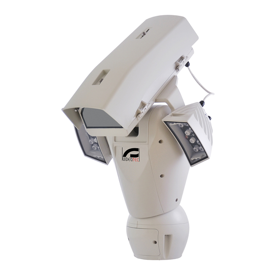
Seite 127
Fig. 110 ULISSE2, versione con due illuminatori a LED. MNVCU2_1638_IT...
Seite 128
FINESTRA IN GERMANIO Fig. 111 ULISSE2, versione per telecamere termiche. MNVCU2_1638_IT...
Seite 129
AREA AREA UTILE UTILE A - A D - D AREA AREA UTILE UTILE A - A C - C DIMENSIONI DELLA FINESTRA Fig. 112 ULISSE2, custodia. MNVCU2_1638_IT...
Seite 130
Email: info@videotec.com Tel. +33 1 60491816 - Fax +33 1 69284736 Email: info.fr@videotec.com Asia Pacific Videotec (HK) Ltd Americas Videotec Security, Inc. Flat 8, 19/F. On Dak Industrial Building, No. 2-6 Wah Sing Street Gateway Industrial Park, 35 Gateway Drive, Suite 100 Kwai Chung, New Territories - Hong Kong Plattsburgh, NY 12901 - U.S.A.
Seite 131
FRANÇAIS ULISSE2 PTZ Full IP universel pour caméras IP Français - Manuel d’instructions...
Seite 133
Sommaire F R A N Ç A I S 1 À propos de ce mode d’emploi ..................7 1.1 Conventions typographiques ..........................7 2 Notes sur le copyright et informations sur les marques de commerce ..... 7 3 Normes de securité ......................8 4 Identification ........................
Seite 134
8.2 Branchement de la tourelle à l’installation ....................23 8.2.1 Description de la carte de connexion ..........................23 8.2.2 Connexion de la ligne d'alimentation ..........................23 8.2.3 Connexion des câbles de signalisation ..........................24 8.2.3.1 Branchement du câble de réseau Ethernet ............................24 8.2.3.2 Branchement des entrées d'alarme, de l'interrupteur crépusculaire et des relais ..............24 8.3 Sélection du mode de fonctionnement de l’unité...
1 À propos de ce mode DANGER! d’emploi Émission de lumière visible ou infrarouge. Peut être dangereux pour les yeux. Suivre les indications fournies. Avant d'installer et d'utiliser cette unité, lire attentivement toute la documentation fournie. ATTENTION! Garder le manuel à portée de main pour des Risque moyen.
3 Normes de securité ATTENTION! L'installation est du type TNV- 1. Ne pas la connecter à des circuits SELV. ATTENTION! Le circuit électrique auquel l'unité est reliée doit être équipé d'un ATTENTION! Pour réduire les risques interrupteur de protection bipolaire d’incendie, utiliser uniquement des câbles automatique de 20A max.
Seite 139
• Ne pas utiliser de câbles usés ou endommagés. • La catégorie d’installation (ou catégorie de surtension) spécifie les niveaux de la tension de • Ne procéder sous aucun prétexte à des secteur correspondant à l’appareil. La catégorie modifications ou des connexions non prévues dépend du lieu d’installation et du dispositif dans ce manuel.
Partie supérieure du caisson. produit Caméra et optique motorisée tierces (non fournies)/Caméra avec optique intégrée ULISSE2 est une unité PTZ Full IP d'extérieur pour la tierce (non fournies)/Module caméra visible gestion complète et le contrôle de toutes les caméras (accessoire).
5 Versions 4.3 Marquage du produit 5.1 Fenêtre en germanium Les tourelles portent un étiquette conforme au marquage CE. La version équipé d’une fenêtre au germanium, est prévue pour protéger les caméras thermiques des agressions climatiques extérieures. Fig. 2 L'étiquette indique: •...
6 Préparation du produit en 6.3 Contenu vue de l’utilisation Contrôler que le contenu correspond à la liste matériel indiquée ci-dessous: Toute modification non approuvée • Unité de positionnement expressément par le fabricant entraînera • Base d'alimentation l’annulation de la garantie. •...
6.5 Opérations à effectuer avant 6.5.3 Préconfiguration de la caméra tierce l’installation Le système peut être interfacé avec un 6.5.1 Fixation du support VMS (Video Management System) de Plusieurs types de supports sont disponibles (11 2 manières différentes: (8.3.1 Description Accessoires, page 50). Choisir le support convenable du mode Master Selection, page 25).
7 Assemblage 7.3 Montage caméras, systèmes optiques motorisés 7.1 Caractéristiques des caméras Le montage de la caméra et des objectifs • On peut monter seulement des caméras avec porte correspondants est laissé aux soins du client. de communication Ethernet de type 100 baseTx. 7.3.1 Ouverture du caisson •...
7.3.2 Installation de la caméra Selon la forme ou la taille de l’optique, vous devrez peut-être utiliser une entretoise. Alignez le trou de La caméra et ses optiques doivent être installées dans l’entretoise sur le trou de l'optique. le caisson à l’aide de la glissière prévue à cet effet (utilisez les vis et les rondelles fournies).
Seite 146
Alignez le bord de l’optique sur le bord de la glissière. Replacez la glissière principale sur le bloc caméra/ optique/glissière. Faites coïncider le trou de la glissière de la caméra avec l'œillet de la glissière principale choisi précédemment (01). Vissez en partie les vis de la glissière de la caméra (vis et rondelles fournies).
7.4.1 Description de la carte du caisson Placez la caméra dans le caisson et fixez-la à l’aide des vis et des rondelles. DESCRIPTION DE LA CARTE Compo- Fonction sant Non utilisé RS-485 (optique) Lecture des potentiomètres de l’optique Alimentation des moteurs de l’optique, One Push AF Alimentation des moteurs de l’optique, One Push AF, lecture des potentiomètres de l’optique Visible cut filter...
7.4.3 Branchement de la caméra réseau J6 LD8 J8 J9 LD10 Branchez l’alimentation, la ligne de données et les alarmes (en option) de la caméra, comme illustré dans la figure. Si la tourelle est contrôlée avec le mode Camera Master, reliez la ligne sérielle LD11 de contrôle RS-485 (8.3 Sélection du mode de DIP2...
7.4.4 Branchement des optiques 7.4.4.3 Réglage de la tension d'alimentation des moteurs des optiques motorisées contrôlées en tension Avant d’alimenter la tourelle, sélectionnez la tension Toutes les options de configuration doivent être d’alimentation des optiques en agissant sur le définies dans le chapitre correspondant (10.3.2 Page DIP switch de tension des optiques (DIP2, 7.4.1 Configuration du Matériel, page 33).
7.4.4.5 One Push Autofocus 7.4.6 Installation du module caméra visible (en option) Certains types d’optiques motorisées sont en mesure de gérer l’autofocus. Démontez la glissière présente dans le caisson et Effectuer les connexions comme illustré en figure. fixez-la au module caméra. Utilisez les vis et les rondelles fournies.
7.4.7 Installation du corps supérieur du 7.4.8 Fermeture du caisson caisson avec vitre chauffée antigel et Au terme des opérations d'installation et de câblage, essuie-glace (en option) refermer le produit. Contrôlez la présence et le bon état de la garniture Débranchez le câble d’alimentation de l’essuie- du caisson.
Seite 152
Ouvrir le panneau de configuration en desserrant les Après avoir positionné le joint (01), fixer la base (02) vis comme illustré en figure. au support (03) en utilisant les vis (04), les rondelles à dents (05) et les bagues pour vis (06). Passer les câbles dans les presse-câbles en maintenant la base à...
8.2 Branchement de la tourelle à 8.2.2 Connexion de la ligne d'alimentation l’installation Selon la version, différentes tensions d'alimentation 8.2.1 Description de la carte de peuvent être fournies au dispositif. La valeur de connexion tension d'alimentation est reportée sur l'étiquette d'identification du produit (4.3 Marquage du produit, DESCRIPTION DE LA CARTE page 11).
8.2.3.2 Branchement des entrées d'alarme, Effectuer les connections selon ce qui est décrit dans le tableau. de l'interrupteur crépusculaire et des relais La longueur maximale du câble de chaque alarme est CONNEXION DE LA LIGNE D'ALIMENTATION de 200 m. Utilisez les câbles blindés. Couleur Borne Branchez le câble des entrées/sorties numériques au...
8.3 Sélection du mode de Camera Master: Le VMS interagit toujours avec la caméra via le driver spécifique. Avec cette fonctionnement de l’unité configuration, la caméra contrôle la tourelle par le biais de la ligne sérielle RS-485. La base contient un DIP switch qui permet de configurer le mode Master Selection et les standards d’usine (DIP1, 8.2.1 Description de la carte de connexion, page 23).
8.5 Installation de la carte 8.3.2 Description de la procédure des standards d'usine mémoire Si le mot de passe d'accès n'est plus disponible, il est Vous pouvez doter l’appareil d’une carte mémoire de possible de rétablir les programmations d'usine à type Micro SD.
être montés de la base. Veillez à ne pas abîmer les composants ensemble. intérieurs lors de l’installation. Seuls des projecteurs VIDEOTEC peuvent être installés sur la tourelle. 8.7.1 Montage de l’étrier Positionner l’étrier (01) sur la partie inférieure du caisson comme illustré...
8.7.2 Montage du projecteur sur l’étrier Alignez les projecteurs sur la caméra de manière à disperser le moins de lumière possible. Positionner les fixations du projecteur (01) sur celles Vissez les vis et les rondelles présentes, fournies avec de l'étrier (02). le projecteur.
8.8 Branchement des projecteur 8.9 Réglage et modalité à LED d'activation des projecteurs à Ouvrir le caisson selon la description dans le chapitre correspondant (7.3.1 Ouverture du caisson, page 14). Une fois le réglage effectué, le projecteur Master Introduire les câbles d'alimentation de 10 cm au synchronise et contrôle le projecteur Slave.
8.9.1 Réglage du seuil d'allumage des 8.9.2 Réglage de la puissance des projecteurs à LED projecteurs à LED Le projecteur est réglé en usine afin de distribuer la puissance maximale. S'il ne fallait pas éclairer des sujets éloignés ou si l’image était surexposée à cause de la luminosité...
8.9.3 Activation des projecteurs à LED 8.9.5 Activation des projecteurs à LED à à l'aide d'un interrupteur crépusculaire l'aide de la caméra externe Les projecteurs à LED sont activés selon la détection de la luminosité de la scène cadrée par la caméra. Ce Les projecteurs à...
9 Allumage 10 Configuration 10.1 Adresse IP par défaut S'assurer que l'unité et les autres composants de l'installation soient fermés de façon à empêcher le contact avec les L’appareil est configuré pour obtenir composants sous tension. l’adresse IP depuis un serveur DHCP. L’adresse IP acquise via DHCP est visible dans le Durant le fonctionnement normal, la fichier journal du serveur DHCP.
10.3 Interface web 10.3.2 Page Configuration du Matériel Dans la rubrique du menu Configuration du Matériel, Logiciels de navigation supportés: vous pouvez configurer le matériel de l’appareil. Microsoft Internet Explorer, Google La visualisation de certains champs de produit Chrome, Mozilla Firefox. de manière dynamique selon la configuration du système.
Seite 164
• Port Série: Type de communication pour contrôler • Baudrate: Sélectionne le débit en bauds à le dispositif. utiliser pour communiquer avec l'optique. • Protocole: Protocole de communication. • Type Sériel: Sélectionne le mode de communication avec l'optique. • Envoi d'ACK: Permet d'envoyer l'ACK pour •...
Seite 165
• Accessoires: Présence ou non d’accessoires installés sur l’appareil. • Essuie-glace : Active le fonctionnement de l’essuie-glace. • Projecteurs: Active le fonctionnement des projecteurs. (11.3 Projecteurs à LED, page 50). • Verre Réchauffé: Active le fonctionnement du verre réchauffé. (11.7 Vitre chauffée antigel, page 51).
10.3.3 Page Home 10.3.3.2 État du système Lors du démarrage, dans l’espace de l’instantané, il Si le login est effectué avec succès, on pourra voir est possible de visualiser l’état du système. l'interface de gestion de le produit. La page Accueil permet de voir l’état du système, d’afficher l’instantané...
10.3.3.3 Mouvement horizontal et vertical • Focus Proche/Focus Loin/Autofocus: L’Autofocus est disponible seulement avec le module caméra Le clavier virtuel permet de déplacer l’appareil. Pour visible ou les optiques motorisées dotées de définir la vitesse, utilisez le menu déroulant présent l’autofocus.
10.3.3.8 Gestion du preset 10.3.3.9 Contrôle du relais et de l’état des alarmes • Recall Présélection/Sauvegarder Présélection/Eliminer la Présélection • Activer le Relais/Désactiver le Relais: Une fois que vous avez sélectionné le relais dans le menu déroulant, vous pouvez en définir l’état du contact. Fig.
10.3.4 Page Paramètres Dispositif 10.3.6 Page Réseau A la mention du menu Paramètres Dispositif il est Pour un fonctionnement correct du possible de configurer le nom de le dispositif et dispositif, il faut le synchroniser au logiciel d'afficher d'autres informations supplementaire. VMS en utilisant un serveur NTP.
10.3.7 Page Utilisateurs • Facteur Tilt: Configure le facteur de réduction de la vitesse manuelle de l’axe tilt. Calcul de la A la mention du menu Configuration Utilisateurs il vitesse de mouvement : vitesse de l'axe inclinaison est possible d'administrer les utilisateurs qui peuvent (Tilt) = vitesse nominale d'inclinaison / facteur accéder à...
10.3.9 Page Autopan 10.3.11 Page Rappel Mouvements A la mention du menu Autopan il est possible À l'entrée du menu Rappel Mouvements, vous d'indiquer le preset de début et de fin de l'autopan. pouvez spécifier les intervalles de temps après lesquels la tourelle exécutera des fonctions Il est possible de configurer la vitesse à...
10.3.12 Page Preset 10.3.14 Page Entrées Numériques A la mention du menu Preset on peut configurer À l'entrée du menu Entrées Numériques, vous pouvez certains paramètres concernant les preset: configurer les canaux numériques présents sur le dispositif. Il y a ci-dessous une courte description •...
Pour un contrôle du fonctionnement correct des La visualisation de certains champs de produit alarmes, dans la page web se trouve un petit rond. Le de manière dynamique selon la configuration du petit rond sera vert dans les conditions normales et système.
10.3.17 Page Mode Nuit • Paramètres de la Caméra: Définissent les niveaux et les retards pour le passage entre les modes Nuit Dans la rubrique du menu Mode Nuit, vous pouvez et Jour. configurer l'activation des projecteurs. • Seuil Jour-Nuit: Définit le niveau de lumière La visualisation de certains champs de produit sous lequel la tourelle active le mode Nuit.
10.3.18 Page Installation de Lavage • Retard Activation Essuie-glace: Intervalle de temps qui se passe entre le début de la distribution La page de configuration est disponible uniquement de l'eau et l'activation de l'essuie-glace. si l'accessoire relatif est présent (11.1 Système de •...
10.3.19 Page Configuration Caméra • Exposition: Paramètres de configuration • Mode Exposition: Ce paramètre configure 10.3.19.1 Caméra tierce l'algorithme d'exposition (AUTO, MANUAL, IRIS, Le produit, avec adresse IP générée SHUTTER, BRIGHT). Les champs de contrôle automatiquement, n'est pas en mesure de correspondants sont affichés en fonction de la transmettre le streaming vidéo.
Seite 177
• Équilibre Blanc: Paramètres de configuration • Modalité Defog: Ce paramètre active la fonction permettant d'améliorer la vision en cas • Mode: Cela permet de configurer la balance du de brouillard. blanc en mode automatique ou manuel. • Correction de la Surexposition: Ce paramètre •...
10.3.20 Page Masquage • Position de Début du Masque: Configurez le point d’activation du masque. La page de configuration est disponible uniquement si l'accessoire relatif est présent (11.6 Module caméra visible, page 51). Dans la rubrique du menu Masquage, vous pouvez définir les zones qui apparaissent obscures à...
10.3.21 Page Registre Système 10.3.22 Page Instruments Dans la rubrique du menu Registre Système, vous A la mention du menu Instruments il est possible pouvez afficher l’historique des événements. de reconfigurer les valeurs prédéfinies pour toute la configuration de la tourelle ou seulement pour Le système peut détecter différents types de certaines sections spécifiques.
11.2 Bride de support pour Fig. 105 UPTWBA. projecteurs à LED 11.5 Support fixation sol Pour installer les projecteurs à LED VIDEOTEC, vous pouvez équiper l’appareil d’une bride de support. Support de fixation au sol avec passage interne des câbles.
11.6 Module caméra visible 11.7 Vitre chauffée antigel L’appareil peut être équipé d’une caméra à spectre Le produit peut être muni de verre réchauffé visible. antigivre. Caméra complémentaire Full HD 1080p, 30x (4,3- 129 mm), 60 fps, température jusqu’à +65 °C. Fig. 108 UPTBVTR. Pour d'autres renseignements se référer à...
électriques. et alcali. L’emploi de ce type de produits abîme d’une façon irréparable la surface Si vous contactez le service technique de VIDEOTEC traitée. ou un centre d'assistance agréé, vous devez fournir le numéro de série du produit (4.3 Marquage du Il est conseillé...
PROBLÈME L'interface logicielle affiche le message suivant: Pour toute problématique non décrite ou si les problèmes énumérés ci-après persistent, contactez le service technique VIDEOTEC ou un centre d'assistance agréé. PROBLÈME Le produit ne s'allume pas. CAUSE Câblage incorrect, rupture des fusibles.
Seite 184
PROBLÈME Le journal système affiche le PROBLÈME L'interface logicielle affiche le message d'erreur suivant : message suivant: MicroSD... CAUSE Le système ne peut pas gérer la carte Micro SD installée. SOLUTION Vérifiez que la carte Micro SD est compatible avec le système. En cas de dysfonctionnement, remplacez la carte Micro SD.
Seite 185
PROBLÈME Durant l'allumage, la tourelle reste PROBLÈME Il n'est pas possible de mettre bloquée et l'interface logicielle au point l'image avec l'optique affiche le message suivant: motorisée: CAUSE Réglage du Back Focus non correct. SOLUTION Exécuter la procédure suivante en cadrant le sujet à...
16.6 Caméra Caméra complémentaire en option VIDEOTEC (code CAMHD30X) Spécifications des caméras pouvant être installées Day/Night Full HD 30x Capteur d'image: 1/2.8 type Exmor™ CMOS sensor Diverses modes de communication avec la caméra IP : Pixels effectifs: environ 2.38 Megapixels • la tourelle contrôle la caméra IP via ONVIF S (PTZ Éclairage minimum, couleur (ICR-OFF):...
16.7 Environnement 16.8 Certifications Intérieur/Extérieur Sécurité électrique (CE): EN60950-1, IEC60950-1 Température de fonctionnement: de -40°C jusqu'à Compatibilité électromagnétique (CE): EN50130-4, +65°C EN61000-6-4, EN55022 (Classe A), EN55032 (Classe A), FCC Part 15 (Classe A) Intervention de la fonction de dégivrage: de -40°C jusqu'à...
17 Dessins techniques Les dimensions des dessins sont exprimées en millimètres. Fig. 109 ULISSE2. MNVCU2_1638_FR...
Seite 191
Fig. 110 ULISSE2, version avec 2 projecteurs à LED. MNVCU2_1638_FR...
Seite 192
FENÊTRE EN GERMANIUM Fig. 111 ULISSE2, version pour caméras thermiques. MNVCU2_1638_FR...
Seite 193
SURFACE SURFACE UTILE UTILE A - A D - D SURFACE SURFACE UTILE UTILE A - A C - C DIMENSIONS FENÊTRE Fig. 112 ULISSE2, caisson. MNVCU2_1638_FR...
Seite 194
Email: info@videotec.com Tel. +33 1 60491816 - Fax +33 1 69284736 Email: info.fr@videotec.com Asia Pacific Videotec (HK) Ltd Americas Videotec Security, Inc. Flat 8, 19/F. On Dak Industrial Building, No. 2-6 Wah Sing Street Gateway Industrial Park, 35 Gateway Drive, Suite 100 Kwai Chung, New Territories - Hong Kong Plattsburgh, NY 12901 - U.S.A.
Seite 195
DEUTSCH ULISSE2 Universelles PTZ Full IP für IP-Kameras Deutsch - Bedienungsanleitung...
Seite 197
Inhaltsverzeichnis D E U T S C H 1 Allgemeines ........................7 1.1 Schreibweisen ................................7 2 Anmerkungen zum Copyright und Informationen zu den Handelsmarken ..... 7 3 Sicherheitsnormen ......................8 4 Identifizierung ......................10 4.1 Beschreibung und Bezeichnung des Produktes ..................10 4.2 Produktübersicht ..............................10 4.3 Kennzeichnung des Produkts..........................11 4.3.1 Prüfung der Kennzeichnung .............................11...
Seite 198
8.2 Anschluss des Schwenk-Neige-Kopfs an die Anlage ................23 8.2.1 Beschreibung der Karte Anschlüsse ..........................23 8.2.2 Anschluss der Stromversorgung ............................23 8.2.3 Anschluss der Signalkabel..............................24 8.2.3.1 Anschluss der Ethernet-Kabel ................................24 8.2.3.2 Anschluss der Alarmeingänge, der Dämmerungsschalter und der Relais ................24 8.3 Auswahl des Betriebsmodus der Einheit ......................25 8.3.1 Beschreibung des Modus Master Selection .........................25 8.3.2 Beschreibung des Vorgangs Factory Default (werkseitige Anfangseinstellungen) ........26 8.4 Schließen der kleinen Klappe der Steckverbinder ..................26...
Seite 199
10.3.12 Seite Preset..................................42 10.3.13 Seite Preset (Fortgeschritten) ............................42 10.3.14 Seite Digitaleingänge ..............................42 10.3.15 Seite Digitalausgänge ..............................43 10.3.16 Seite Hilfsbefehle ................................43 10.3.17 Seite Nachtmodus ................................44 10.3.18 Seite Scheibenwaschanlage ............................45 10.3.19 Kamera-Einstellungen Seite............................46 10.3.19.1 Kamera von Drittanbietern ................................46 10.3.19.2 Kamera-Modul sichtbar ..................................46 10.3.20 Seite Maskierung ................................48 10.3.21 Seite Systemaufzeichnung ............................49 10.3.22 Werkzeuge Seite ................................49...
1 Allgemeines GEFAHR! Emission von sichtbarem oder infrarotem Vor Installation und Anwendung der Einheit ist die Licht. gesamte gelieferte Dokumentation aufmerksam zu Kann zu Verletzungen an den Augen lesen. Zum späteren Nachschlagen das Handbuch in führen. Die mitgelieferten Informationen Reichweite aufbewahren. beachten.
3 Sicherheitsnormen ACHTUNG! Die Anlage gehört zum Typ TNV- 1. Nicht an Kreisläufe SELV anschließen. ACHTUNG! Die elektrische Anlage, an der die Einheit angeschlossen ist, muss ACHTUNG! Zur Senkung der Brandgefahr mit einem automatischen zweipoligen dürfen nur UL Listed oder CSA zertifizierte Schutzschalter 20A max ausgestattet sein.
Seite 203
• Es dürfen keine Kabel mit Verschleiß- oder • Die Installationskategorie (auch als Alterungsspuren verwendet werden. Überspannungskategorie bezeichnet) gibt den Pegel der Netzspannungsstöße • Unter keinen Umständen dürfen Veränderungen an, denen die Ausrüstung ausgesetzt ist. oder Anschlüsse vorgenommen werden, die Die Kategorie hängt vom Installationsort in diesem Handbuch nicht genannt sind.
Oberer Teil des Gehäuses. Bezeichnung des Produktes Kamera und motorisierte Optik von Drittanbietern (nicht enthalten)/Kamera mit ULISSE2 ist eine PTZ Full IP-Einheit für den eingebauter Optik von Drittanbietern (nicht Außenbereich. Verwendet wird sie für die Steuerung und Kontrolle sämtlicher IP-Kameras und IP- enthalten)/Kamera-Modul sichtbar (Zubehör).
5 Versionen 4.3 Kennzeichnung des Produkts 5.1 Fensterscheibe aus Auf den Schwenk-Neige-Köpfen befindet sich ein Schildchen, das der CE- Germanium Kennzeichnung entspricht. Die Version ist mit Fensterscheibe aus Germanium ausgestattet, die eigens für Anlagen mit Wärmebildkameras ausgelegt ist. Abb. 2 Das Schildchen nennt: •...
6 Vorbereitung des 6.3 Inhalt Produktes auf den Gebrauch Prüfen Sie, ob der Inhalt mit der nachstehenden Materialliste übereinstimmt: Jede vom Hersteller nicht ausdrücklich • Positionierungseinheit genehmigte Veränderung führt zum Verfall • Basis für Netzstromversorgung der Gewährleistungsrechte. • Zubehör Packung: •...
6.5 Auf die Installation 6.5.3 Vorkonfiguration der Kamera von Drittanbietern vorbereitende Tätigkeiten Das System kann mit einem VMS 6.5.1 Befestigung der Halterung (Video Management System) auf zwei Verschiedene Halterungen sind (11 Zubehör, Seite verschiedene Arten verbunden werden: 50). Das geeignetste für die Installation auswählen (8.3.1 Beschreibung des Modus Master und alle Angaben aus diesem Kapitel befolgen.
7 Zusammenbau 7.3 Montage Kamera und motorisch bewegte Optiken 7.1 Eigenschaften der Kameras Die Kamera und die zugehörigen Objektive sind vom • Nur Kameras mit Ethernet-Kommunikations Kunden selbst zu montieren. anschluss vom Typ 100 baseTx können montiert 7.3.1 Öffnung des Schutzgehause werden.
7.3.2 Installation der Kamera Je nach Form und Dimension der Optik kann die Notwendigkeit zur Verwendung eines Die Kamera und die Optiken müssen im Abstandsstücks bestehen. Das Loch des Gehäuseinneren unter Verwendung des geeigneten Abstandsstücks mit dem Loch der Optik angleichen. Schlittens installiert werden (die im Lieferumfang enthaltenen Schrauben und Unterlegscheiben verwenden).
Seite 210
Den Optikrand mit dem Schlittenrand anpassen. Den Hauptschlitten erneut auf dem Kamera- / Optik- / Schlittenblock ausrichten. Das Loch des Kameraschlittens mit dem vorher gewählten (01) Langloch des Hauptschlittens zusammenfallen lassen. Die Schrauben des Kameraschlittens (Schrauben und Unterlegscheiben im Lieferumfang enthalten) teilweise festziehen.
7.4.1 Beschreibung der Karte Gehäuse Die Kamera im Gehäuse ausrichten und mit den Schrauben und Unterlegscheiben befestigen. BESCHREIBUNG DER KARTE Kompo- Funktion nente Nicht verwendet. RS-485 (Optik) Erfassung der Potenziometer der Optik Spannungsversorgung der Optikmotoren, One Push AF Spannungsversorgung Optikmotoren, One Push AF, Erfassung der Potenziometer der Optik Visible cut filter Versorgung und Steuerung (eingebaute Kamera)
7.4.3 Anschluss der Netzwerkkamera J6 LD8 J8 J9 LD10 Die Spannungsversorgung, die Datenleitung und die Alarme (fakultativ) der Kamera wie in der Abbildung gezeigt anschließen. Sollte der Schwenk-Neige-Kopf mit dem Modus Camera Master gesteuert werden, LD11 die serielle Kontrollleitung RS-485 anschließen (8.3 DIP2 Auswahl des Betriebsmodus der Einheit, Seite 25).
7.4.4 Verbindung der 7.4.4.3 Einstellung der Versorgungsspannung der Motoren der spannungsgeregelten motorisierten Optiken Optiken Die Spannungsversorgung der Optiken auswählen, Sämtliche Konfigurationsoptionen müssen im bevor der Schwenk-Neige-Kopf mit Strom gespeist entsprechenden Kapitel eingestellt werden (10.3.2 wird. Dabei den DIP-Schalter für die Spannung der Seite Hardware-Konfiguration, Seite 33).
7.4.4.5 One Push Autofocus 7.4.6 Installation des Kameramoduls sichtbar (Sonderausstattung) Einige motorisierte Optiktypen können den Autofokus steuern. Den Schlitten im Gehäuse demontieren und am Die Verbindungen so durchführen, wie in der Kameramodul befestigen. Die im Lieferumfang Abbildung dargestellt. enthaltenen Schrauben und Unterlegscheiben verwenden.
7.4.7 Installation des oberen 7.4.8 Schließen des Gehäuses Gehäusekorpus mit beheizter Nach Beendigung der Installation und der Eisschutzscheibe und Scheibenwischer Verkabelung das Produkt wieder schließen. (Sonderausstattung) Das Vorhandensein und Intaktsein der Dichtung des Gehäuses überprüfen. Das Versorgungskabel des Scheibenwischers trennen. Durch Ausdrehen der Schrauben den Auf die Befestigung achten.
Seite 216
Das Konfigurierungskläppchen wird durch Entfernen Nach der Positionierung der Dichtung (01), die Basis der Schrauben geöffnet, wie in der Abbildung (02) mit den Schrauben (04), den Zahnscheiben (05) gezeigt. und den Ringen für Schrauben (06) an der Halterung (03) befestigen. Die Kabel in den Kabelschellen einführen, während die Basis etwa 20cm von der Halterung entfernt gehalten wird.
8.2 Anschluss des Schwenk- 8.2.2 Anschluss der Stromversorgung Neige-Kopfs an die Anlage Je nach Version kann die Vorrichtung mit unterschiedlichen Versorgungsspannungen geliefert 8.2.1 Beschreibung der Karte werden. Der Wert der Versorgungsspannung ist auf dem Kenndatenschildchen des Produktes Anschlüsse angegeben. (4.3 Kennzeichnung des Produkts, Seite BESCHREIBUNG DER KARTE 11).
8.2.3.2 Anschluss der Alarmeingänge, der Die Anschlüsse der Beschreibung in der Tabelle entsprechend ausführen. Dämmerungsschalter und der Relais Die max. Kabellänge für jeden Alarm beträgt 200 m. ANSCHLUSS DER STROMVERSORGUNG Geschirmte Kabel verwenden. Farbe Klemme Das Kabel der digitalen E/A mit dem entsprechenden Netzteil 230Vac Steckanschluss verbinden (J3, 8.2.1 Beschreibung der Blau...
8.3 Auswahl des Betriebsmodus Camera Master: Das VMS kommuniziert immer über den speziellen Driver mit der Kamera. Die der Einheit Kamera steuert den Schwenk-Neige-Kopf mit dieser Konfiguration über die serielle Leitung RS-485. In der Basis befindet sich ein DIP-Schalter, mit dem der Modus Master Selection und Factory Default konfiguriert werden können (DIP1, 8.2.1 Beschreibung der Karte Anschlüsse, Seite 23).
8.5 Installation der Speicherkarte 8.3.2 Beschreibung des Vorgangs Factory Default (werkseitige Die Einheit kann mit Micro-SD-Karte ausgestattet Anfangseinstellungen) werden. Die Speicherkarte kann zur Datensicherung aller Konfigurationen und Systemlogdateien Wenn das Zugangskennwort nicht mehr auffindbar verwendet werden, um die Wartung oder den ist, können die Werkseinstellungen über eine Austausch bei Fehlfunktionen zu erleichtern.
Genau darauf achten, die internen Komponenten während der Installation nicht zu Am Schwenk-Neige-Kopf dürfen nur beschädigen. Scheinwerfer von VIDEOTEC installiert werden. 8.7.1 Bügelmontage Den Bügel (01) im unteren Teil des Gehäuses positionieren, wie in der Abbildung gezeigt. Die Schrauben und die Unterlegescheiben (02) in die Bohrungen (03) einfügen und festziehen.
8.7.2 Montage des Scheinwerfers auf Die Scheinwerfer an die Kamera anpassen, sodass das Licht so wenig wie möglich streut. den Bügel Die im Lieferumfang des Scheinwerfers enthaltenen Befestigungen des Scheinwerfers (01) an denen des Schrauben und Unterlegscheiben festziehen. Bügels (02) anbringen. Abb.
8.8 Anschluss der LED- 8.9 Einstellung und Scheinwerfer Aktivierungsarten der LED- Scheinwerfer Das Gehäuse nach der Erläuterung im zugehörigen Kapitel öffnen (7.3.1 Öffnung des Schutzgehause, Nach durchgeführter Einstellung synchronisiert und Seite 14). steuert der Scheinwerfer Master den Scheinwerfer Die Versorgungskabel um mindestens 10 Slave.
8.9.1 Einstellung der Einschaltschwelle 8.9.2 Einstellung der Leistung der LED- der LED-Scheinwerfer. Scheinwerfer. Der Scheinwerfer wird im Werk zur Erbringung maximaler Leistung eingestellt. Falls es nicht nötig sein sollte, entfernte Objekte zu beleuchten oder wenn das Bild wegen zu hoher Lichtintensität zu stark angestrahlt ist, die Leistung regulieren, sie zu verringern und Energie zu sparen.
8.9.3 Aktivierung der LED- 8.9.5 Aktivierung der LED-Scheinwerfer Scheinwerfer durch einen externen durch die Kamera Dämmerungsschalter Die LED-Scheinwerfer werden basierend auf der erfassten Helligkeit der von der Kamera Die LED-Scheinwerfer werden von einem externen aufgenommenen Szene aktiviert. Dieser Dämmerungssensor aktiviert. Dieser ist an einem Betriebsmodus steht nur zur Auswahl, wenn die Alarmeingang angeschlossen.
9 Einschaltung 10 Konfiguration 10.1 Vorgegebene IP-Adresse Sicherstellen, das die Einheit und die anderen Bauteile der Anlage korrekt geschlossen sind, um den Kontakt mit Die Einheit ist konfiguriert, um eine unter Spannung stehenden Bauteilen zu IP-Adresse von einem DHCP-Server zu verhindern.
10.3 Web-Schnittstelle 10.3.2 Seite Hardware-Konfiguration Unter dem Menüpunkt Hardware-Konfiguration kann Unterstützte Browser: Microsoft Internet die Hardware der Einheit konfiguriert werden. Explorer, Google Chrome, Mozilla Firefox. Die Anzeige einiger Bereiche erfolgt je nach Systemkonfiguration dynamisch. 10.3.1 Erster Webseitenaufruf • Kameratyp: Kommunikationsmodus der Kamera Der erste Schritt zur Konfiguration der Einrichtung ist (nur für den Modus PTZ Master).
Seite 228
• Serieller Anschluss: Kommunikationstypologie • Baudrate: Auswahl der für die Kommunikation zur Steuerung des Geräts. mit der Optik zu verwendenden Baudrate. • Protokoll: Kommunikationsprotokoll. • Serientyp: Auswahl des Kommunikationsmodus mit der Optik. • ACK Senden: Aktivierung des Sendens von ACK •...
Seite 229
• Zubehör: Vorhandensein oder Fehlen von in dem Gerät eingebautem Zubehör. • Scheibenwischer: Aktiviert den Betrieb der Scheibenwischer. • Scheinwerfer: Aktiviert den Betrieb der Scheinwerfer. (11.3 LED Scheinwerfer, Seite 50). • Beheizte Scheibe: Aktiviert den Betrieb der beheizten Scheibe. (11.7 Heizbares Vereisungsschutz-Glas, Seite 51).
10.3.3 Home Seite 10.3.3.2 Systemstatus Bei der Inbetriebnahme wird in dem Bereich des Wenn der Login erfolgreich abgeschlossen wurde, Snapshots der Systemstatus angezeigt. wird die Steuer-Schnittstelle des Produktes angezeigt. Auf der Startseite ist folgendes möglich: Einsehen des Systemstatus, Anzeige des Kamera-Snapshots, Bewegung der Einheit, Steuerung der Optiken und des Zubehörs, Aktivierung der Relais und Überwachung des Status der Alarmeingänge.
10.3.3.3 Horizontale und vertikale • Fokus Nah/Fokus Weit/Autofokus: Der Autofokus ist nur mit sichtbarem Kamera-Modul oder mit Bewegung motorisierten Optiken mit Autofokus verfügbar. Mit der Bildschirmtastatur kann die Einheit bewegt werden. Zum Einstellen der Geschwindigkeit das unter der Bildschirmtastatur vorhandene Aufklapp- Menü...
10.3.3.8 Steuerung Preset 10.3.3.9 Kontrolle Relais und Alarmstatus • Gehen zu Preset/Preset Speichern/Preset • Relais Aktivieren/Relais Deaktivieren: Nach Löschen Auswahl des Relais im Ausklapp-Menü kann der Status des Kontakts eingestellt werden. Abb. 71 • AL1/AL2/AL3/AL4/ALHOUSING/RL1/RL2/DNH OUSING: Anzeige des Status der Alarme und der Relais.
10.3.4 Geräteparameter Seite 10.3.6 Seite Netzwerk Im Menü-Eintrag Geräteparameter können der Damit das Gerät korrekt funktioniert, muss Name der Einrichtung eingestellt und andere es über einen NTP-Server mit der VMS- Zusatzinformationen angezeigt werden. Software synchronisiert werden. Im Menü-Eintrag Netzwerk kann die Netzwerk- Einstellung des Schwenk-Neige-Kopfes geändert werden.
10.3.7 Seite Nutzer • Tilt-Faktor: Reduzierfaktor für die manuelle Geschwindigkeit der Tiltachse. Berechnung der Im Menü-Eintrag Benutzer-Konfiguration können Bewegungsgeschwindigkeit: Geschwindigkeit die Benutzer verwaltet werden, die Zugriff auf die Neigungsachse (Tilt) = Nenngeschwindigkeit Einrichtung haben. Die Nutzer „Administrator“ Neigung / Neigungsfaktor. können auf die gesamte Konfiguration des Geräts •...
10.3.9 Autopan Seite 10.3.11 Bewegungsanforderung Seite Im Menü-Eintrag Autopan können die Presets für Unter dem Menüpunkt Bewegungsaufruf können die Beginn und Ende des Autopan angegeben werden. zeitlichen Intervalle festgelegt werden, nach denen der Schwenk-Neige-Kopf bestimmte Funktionen Es ist möglich, die Geschwindigkeit einzustellen, mit durchführen wird.
10.3.12 Seite Preset 10.3.14 Seite Digitaleingänge Im Menü-Eintrag Preset sind einige Parameter der Unter dem Menüpunkt Digitaleingänge können die Presets konfigurierbar: im Gerät vorhandenen Digitalkanäle konfiguriert werden. Es folgt eine kurze Beschreibung der • Scan Geschwindigkeit: Geschwindigkeit in Grad konfigurierbaren Parameter für jeden Digitaleingang. pro Sekunde, mit der ein Preset auf ausdrückliche •...
Zur Kontrolle des einwandfreien Betriebs der Die Anzeige einiger Bereiche erfolgt je nach Alarme erscheint auf der Web-Seite ein Punkt, der Systemkonfiguration dynamisch. im Normalzustand grün ist, und rot, wenn ein Alarm 10.3.16 Seite Hilfsbefehle erkannt wird. Der Punkt ist grün im Normalzustand Unter dem Menüpunkt Hilfsbefehle kann die mittels und rot wenn ein Alarm erkannt wird.
10.3.17 Seite Nachtmodus • Kameraparameter: Einstellung der Stufen und der Verzögerungen beim Übergang zwischen dem Unter dem Menüpunkt Nachtmodus kann die Nacht- und Tagmodus. Aktivierung der Scheinwerfer konfiguriert werden. • Grenzwert Tag-Nacht: Einstellung der Die Anzeige einiger Bereiche erfolgt je nach Lichtstufe, unter dieser der Schwenk-Neige-Kopf Systemkonfiguration dynamisch.
10.3.18 Seite Scheibenwaschanlage • Verzögerung Scheibenwischer-Aktivierung: Zeitraum, der zwischen dem Beginn der Die Konfigurationsseite ist nur verfügbar, wenn Wasserabgabe und der Einschaltung des das entsprechende Zubehör vorhanden ist (11.1 Scheibenwischers vergeht. Waschanlage, Seite 50). • Waschdauer: Dauer der Wasserabgabe durch die Im Menü-Eintrag Scheibenwaschanlage kann der Pumpe.
10.3.19 Kamera-Einstellungen Seite • Belichtung: Konfigurationsparameter • Modus Belichtung: Der Parameter konfiguriert 10.3.19.1 Kamera von Drittanbietern den Belichtungsalgorithmus (AUTO, MANUAL, Das Produkt mit selbst generierter IP- IRIS, SHUTTER, BRIGHT). Die entsprechenden Adresse kann das Videostreaming nicht Kontrollfelder werden basierend auf dem übertragen.
Seite 241
• Weißabgleich: Konfigurationsparameter • Defog-Modus: Der Parameter aktiviert die Funktion, welche die Sicht bei Nebel verbessert. • Modus: Damit kann die Weißbilanz entweder • Glanzlichtkorrektur: Der Parameter aktiviert manuell oder automatisch eingerichtet werden. die Funktion, welche die Maskierung der • Wide Dynamic Range: Konfigurationsparameter überbelichteten Bereiche durchführt.
10.3.20 Seite Maskierung • Position Anfang Maske: Konfiguration des Aktivierungspunkts der Maske. Die Konfigurationsseite ist nur verfügbar, wenn das entsprechende Zubehör vorhanden ist (11.6 Kamera- Modul sichtbar, Seite 51). Unter dem Menüpunkt Maskierung können Bereiche bestimmt werden, die auf dem Video verdunkelt Abb.
10.3.21 Seite Systemaufzeichnung 10.3.22 Werkzeuge Seite Unter dem Menüpunkt Systemaufzeichnung kann die Im Menü-Eintrag Werkzeuge können die Ereignishistorie angezeigt werden. gesamte Konfiguration der Einrichtung oder nur bestimmte Abschnitte auf die vordefinierten Werte Das System kann verschiedene Statusänderungen zurückgesetzt werden. erfassen. Außerdem kann in diesem Abschnitt: Die Knöpfe unter dem Logfenster gestatten die Filterauswahl in Abhängigkeit der Gewichtung.
Scheibenwaschanlage, Seite 45). 11.2 Bügelhalterung für LED- Abb. 105 UPTWBA. Scheinwerfer 11.5 Halterung für Brüstungsmontage Für die Installation der LED-Scheinwerfer von VIDEOTEC muss das Gerät mit einer Bügelhalterung Brüstunghalterung mit interner Kabelführung. ausgestattet werden. Abb. 106 UPTWBTAB. Abb. 103 UPTIRNBKT. MNVCU2_1638_DE...
11.6 Kamera-Modul sichtbar 11.7 Heizbares Vereisungsschutz- Glas Die Einheit kann mit einer Spektralkamera ausgestattet werden. Das Produkt kann mit einer beheizten Add-on Kamera Full HD1080p, 30x (4.3-129mm), Eisschutzscheibe ausgestattet werden. 60fps, Temperatur bis zu +65°C. Abb. 108 UPTBVTR. Abb. 107 CAMHD30X. Für weitere Infos bitte entsprechendes Für weitere Infos bitte entsprechendes Kapitel beachten (7.4.7 Installation des...
Oberfläche beschädigen. Bei Kontaktaufnahme mit dem Kundendienst von VIDEOTEC oder einem autorisiertem Servicezentrum Es wird empfohlen, ein weiches Tuch und neutrale muss die Seriennummer des Produkts mitgeteilt mit Wasser verdünnte Seife oder ein spezifisches werden (4.3 Kennzeichnung des Produkts, Seite 11 e Reinigungsmittel für Brillengläser zu verwenden.
15 Problemlösung PROBLEM Die Softwareschnittstelle zeigt folgende Meldung: Kontaktieren Sie bitte den Kundendienst von VIDEOTEC oder das autorisierte Servicezentrum bei jedem nicht beschriebenem Problem oder falls das aufgelistete Problem weiterhin bestehen sollte. PROBLEM Das Produkt lässt sich nicht einschalten. URSACHE...
Seite 248
PROBLEM In der Systemlogdatei wird die PROBLEM Die Softwareschnittstelle zeigt Fehlermeldung angezeigt: MicroSD folgende Meldung: URSACHE Das System kann die installierte Micro-SD-Karte nicht nutzen. LÖSUNG Die Kompatibilität der Micro-SD-Karte mit dem System überprüfen. Bei Fehlfunktionen die Micro-SD-Karte austauschen. PROBLEM In der Systemlogdatei werden die Fehler Error on heater hardware, Error on demist hardware und Error on fan hardware angezeigt.
Seite 249
PROBLEM Beim Anschalten bleibt der PROBLEM Mit motorisierter Optik kann keine Schwenk-Neige-Kopf blockiert Fokussierung des Bildes erfolgen: und die Softwareschnittstelle zeigt URSACHE Einstellung des Backfokus nicht folgende Meldung: korrekt. LÖSUNG Folgenden Vorgang durchführen. Dabei ein Subjekt mit mindestens 20 m Abstand aufnehmen. 1-Die Irisblende vollständig öffnen 2-Auf maximale Brennweite (Tele) zoomen.
16 Technische Daten 16.2 Mechanik Kabelverschraubungen: 2xM20 + 1xM16 + 16.1 Allgemeines Spezialdichtung für Kabel RJ45 Konstruktion aus Aluminiumdruckguss und Horizontale Drehung: kontinuierlich Technopolymer Neigung: +90° bis -40° Pulverlackierung mit Epoxydpolyester, Farbe RAL9002 • Schwenkgeschwindigkeit einstellbar: von 0.02°/s Topmount bis 100°/s (von 0.02°/s bis 50°/s mit Scheinwerfern) Die Installation wird durch die Verwendung eines •...
16.3 Fenster für Gehäuse 16.4 Elektrik Fenster für Megapixel-Kameras: (WxH) 125x91mm Versorgungsspannung/Stromaufnahme: Fensterscheibe aus Germanium (Nutzdurchmesser: • 230Vac ±10%, 1.1A, 50/60Hz 61mm) • 24Vac ±10%, 10A, 50/60Hz • Stärke: 2mm • 120Vac ±10%, 2A, 50/60Hz • Außenbehandlung: kratzfest Hard Carbon Coating Leistungsaufnahme: (DLC) + blendfrei •...
Seite 252
16.6 Kamera Zusätzliche Add-on-Kamera VIDEOTEC (Art.-Nr. CAMHD30X) Eigenschaften installierbarer Videokameras Day/Night Full HD 30x Image Sensor: 1/2.8 Typ Exmor™ CMOS Sensor Art der Kommunikation mit der IP-Kamera: Effektive Pixel: ca. 2.38 Megapixels • der Schwenk-Neige-Kopf steuert die IP-Kamera mittels ONVIF S (PTZ Master) Mindestbeleuchtung, Farbe (ICR-OFF): •...
17 Technische Zeichnungen Die Abmessungen der Zeichnungen sind in Millimeter angegeben. Abb. 109 ULISSE2. MNVCU2_1638_DE...
Seite 255
Abb. 110 ULISSE2, Ausführung mit zwei LED-Scheinwerfern. MNVCU2_1638_DE...
Seite 256
FENSTERSCHEIBE AUS GERMANIUM Abb. 111 ULISSE2, Version für Wärmebildkameras. MNVCU2_1638_DE...
Seite 257
NUTZ- NUTZFLÄCHE FLÄCHE A - A D - D NUTZ- NUTZFLÄCHE FLÄCHE A - A C - C FENSTER- ABMESSUNGEN Abb. 112 ULISSE2, Gehäuse. MNVCU2_1638_DE...
Seite 258
Email: info@videotec.com Tel. +33 1 60491816 - Fax +33 1 69284736 Email: info.fr@videotec.com Asia Pacific Videotec (HK) Ltd Americas Videotec Security, Inc. Flat 8, 19/F. On Dak Industrial Building, No. 2-6 Wah Sing Street Gateway Industrial Park, 35 Gateway Drive, Suite 100 Kwai Chung, New Territories - Hong Kong Plattsburgh, NY 12901 - U.S.A.
Seite 259
РУССКИЙ ULISSE2 Универсальное PTZ-устройство Full IP для IP камер Русский - Руководство по эксплуатации...
Seite 261
Содержание Р У С С К И Й 1 О настоящем руководстве ..................7 1.1 Типографские условные обозначения ......................7 2 Примечания в отношении авторского права и информация о торговых марках ..........................7 3 Правила техники безопасности ................8 4 Обозначение ....................... 10 4.1 Описание...
Seite 262
8.1 Крепление основания к опорной конструкции ..................21 8.2 Подсоединение поворотного устройства к системе ................23 8.2.1 Описание платы подключения ............................23 8.2.2 Подключение линии питания ............................23 8.2.3 Подключение сигнального кабеля ..........................24 8.2.3.1 Подключение Ethernet-кабеля ................................24 8.2.3.2 Подключение входов сигнала тревоги, сумеречного выключателя и реле ..............24 8.3 Выбор...
1 О настоящем ОПАСНОСТЬ! руководстве Испускание видимого света или инфракрасного излучения. Может быть вредно для глаз. Обратите Перед установкой и использованием этого внимание на данные указания. оборудования внимательно прочтите всю предоставленную документацию. Всегда держите ПРЕДУПРЕЖДЕНИЕ! руководство под рукой, чтобы им можно было Средний...
3 Правила техники ПРЕДУПРЕЖДЕНИЕ! Установка типа безопасности TNV-1. Это система типа TNV-1, не подключайте ее к SELV-схемам. ПРЕДУПРЕЖДЕНИЕ! Система ПРЕДУПРЕЖДЕНИЕ! Для снижения риска электропитания, к которой возникновения пожара используйте подключается устройство, должна исключительно кабели UL или CSA, иметь автоматический двухполюсный сечение...
Seite 267
• Не используйте кабели, которые кажутся • Категория установки (также называемая изношенными или старыми. категорией перенапряжения) указывает уровень сетевых скачков напряжения, которым • Никогда и ни при каких обстоятельствах не подвержено оборудование. Эта категория выполняйте изменений или подключений, зависит от местоположения оборудования не...
Корпус. браузер к интерфейсу камеры для настройки и Основание. диагностики. Благодаря протоколам ONVIF-S полная IP- связность ULISSE2 позволяет вам управлять всеми функциями поворотного устройства и камеры, включая стеклоочиститель, насос омывателя, предварительные установки, включение осветителей и настройку с помощью наиболее распространенных на рынке программ для...
5 Модели 4.3 Маркировка изделия 5.1 Германиевое окно На поворотных устройствах присутствует этикетка, соответствующая маркировке Модель с германиевым окном была разработана для использования в сочетании с тепловизорами. Рис. 2 На этикетке указаны: Рис. 3 • Идентификационный код модели (Расширенный штрих-код 3/9). •...
6 Подготовка устройства к 6.3 Комплект оборудования использованию Проверьте комплект оборудования на соответствие представленному ниже списку материалов: Любое изменение, которое выполняется без разрешения, явным образом • Устройство позиционирования предоставленного производителем, • Основание с подачей питания аннулирует гарантию. • Упаковка комплектующих: •...
6.5 Подготовительные работы 6.5.3 Предварительная настройка камер других производителей перед установкой Систему можно соединить с VMS (система 6.5.1 Установка кронштейна управления видео) двумя способами: ( Доступны различные виды опорных конструкций 8.3.1 Описание режима выбора главного (11 Комплектующие, страница 50). Выберите устройства (Master Selection), страница подходящий...
7 Монтаж 7.3 Монтаж камеры и объективов с приводом 7.1 Характеристики камер Клиент самостоятельно производит монтаж • Можно устанавливать только камеры с портом камеры и объективов. передачи данных по сети Ethernet типа 100 7.3.1 Как открыть кожух baseTx. Ослабьте 2 винта сбоку и поверните крышку •...
7.3.2 Установка камеры В зависимости от формы и размера объектива, может потребоваться адаптер. Приложите Камера и объектив должны быть установлены в отверстие на адаптере к отверстию на объективе. кожухе на специальных салазках (используйте прилагаемые винты и шайбы). Салазки состоят из двух...
Seite 274
Выровняйте край объектива с краем салазок. Установите главные салазки обратно на блок камеры/объектива/салазок. Выровняйте отверстие салазок камеры относительно ранее выбранного отверстия (01) на главных салазках. Частично затяните винты салазок камеры (прилагаемые винты и гайки). Для обеспечения оптимальной герметичности, используйте плоские и...
7.4.1 Описание платы кожуха Поместите камеру в кожух и закрепите ее с помощью винтов и шайб. ОПИСАНИЕ ПЛАТЫ Элемент Функция Не используется RS-485 (объектив) Считывание потенциометров объектива Питание привода объектива, One Push AF Питание привода объектива, Автоматическая фокусировка одним нажатием кнопки (One-push AF), считывание...
7.4.3 Подключение камеры к сети J6 LD8 J8 J9 LD10 Подключите линию питания, передачи данных и тревоги (на выбор) камеры, как показано на рисунке. В случае если управление поворотной опорой осуществляется в режиме Camera Master, LD11 подключите последовательную линию управления DIP2 RS-485 (8.3 Выбор...
7.4.4 Подключение регулируемых 7.4.4.3 Регулирование напряжения питания приводов объективов объективов с приводом при включении питания Перед включением питания поворотной опоры, выберите напряжение питания объективов, Все параметры настроек необходимо задать используя DIP-переключатель напряжения в соответствующем разделе (10.3.2 Страница объективов (DIP2, 7.4.1 Описание платы кожуха, настройки...
7.4.4.5 One Push Autofocus 7.4.6 Установка модуля камеры видимого спектра (опция) Некоторые виды объективов с приводами оборудованы функцией автоматической Демонтируйте салазки в кожухе и прикрепите их к фокусировки. модулю камеры. Используйте прилагаемые винты Выполните подключение, как показано на рисунке. и шайбы. FOCUS+ FOCUS- ZOOM+...
7.4.7 Установка верхней части 7.4.8 Закрытие корпуса кожуха с противообледенительным После завершения операций по установке и обогреваемым стеклом и прокладке кабелей закройте устройство. стеклоочистителем (опция) Убедитесь, что прокладка кожуха установлена и находится в хорошем состоянии. Отсоедините кабель питания стеклоочистителя. Снимите верхнюю часть кожуха, открутив винты. Будьте...
Seite 280
Откройте дверцу, открутив винты, как показано на Установите уплотнительное кольцо (01) и рисунке. закрепите основание (02) на кронштейне (03) с помощью винтов (04), зубчатых шайб (05) и колец Вставьте кабели в кабельные сальники, удерживая (06). основание на расстоянии около 20 см от опорной конструкции.
8.2 Подсоединение 8.2.2 Подключение линии питания поворотного устройства к В зависимости от модели на устройство может подаваться разное напряжение сети питания. системе Значение напряжения сети питания указано на идентификационном ярлыке устройства. (4.3 8.2.1 Описание платы подключения Маркировка изделия, страница 11). ОПИСАНИЕ ПЛАТЫ Выполнять...
8.2.3.2 Подключение входов сигнала Выполните подключения, как описано в таблице ниже. тревоги, сумеречного выключателя и реле ПОДКЛЮЧЕНИЕ ЛИНИИ ПИТАНИЯ Максимальная длина каждого кабеля для каждого Цвет Клемма сигнала тревоги составляет 200 м. Используйте Источник питания 230Vac экранированные кабели. Синий N (Нейтраль) Подключите...
8.3 Выбор рабочего режима Камера - главное устройство (Camera Master): VMS всегда взаимодействует с камерой, используя устройства специальный драйвер. При такой конфигурации камера управляет поворотным устройством, В основании имеется DIP-переключатель, который используя последовательную линию RS-485. позволяет настроить режим выбора главного устройства...
8.5 Установка карты памяти 8.3.2 Описание процедуры установки заводских настроек В устройство можно установить карту памяти Если пароль доступа уже недействителен, типа micro SD. На карту памяти можно сохранять выполните процедуру возврата к заводским резервные копии всех файлов с системными настройкам.
На поворотном устройстве можно во время установки не повредить внутренние устанавливать только осветители компоненты. VIDEOTEC. 8.7.1 Установка кронштейна Расположите кронштейн (01) на нижней части кожуха, как показано на рисунке. Вставьте винты и шайбы (02) в отверстия (03) и затяните их.
8.7.2 Установка осветителя на Выровняйте осветители относительно камеры, чтобы добиться минимального рассеивания света. кронштейне Прикрутите винты и шайбы, прилагаемые к Расположите крепления осветителя (01) на осветительному прибору. креплениях кронштейна (02). Рис. 46 Рис. 47 Будьте осторожны при установке. Момент затяжки: 6Nm. MNVCU2_1638_RU...
8.8 Подключение 8.9 Регулировка и режим светодиодных осветителей включения светодиодных осветителей Откройте кожух, следуя указаниям в соответствующем разделе (7.3.1 Как открыть После завершения регулировки главный кожух, страница 14). осветитель (Master illuminator) синхронизирует Вставьте кабели питания в кабельные муфты как работу подчиненного осветителя ( Slave минимум...
8.9.1 Регулировка порога включения 8.9.2 Регулировка мощности светодиодных осветителей светодиодных осветителей Производитель настроил осветитель так, чтобы он выдавал максимальную мощность. Если нет необходимости в освещении удаленных объектов или картинка получается слишком светлой, уменьшите мощность, при этом вы снизите потребление энергии. Регулятор...
8.9.3 Включение светодиодных 8.9.5 Включение светодиодных осветителей с помощью внешнего осветителей при помощи камеры сумеречного выключателя Светодиодные осветители включаются в зависимости от уровня освещенности Светодиодные осветители включаются внешним изображения, получаемого от камеры. Этот сумеречным датчиком, подключенным ко входу рабочий режим можно использовать только в том тревоги.
9 Включение 10 Конфигурация 10.1 Заданный по умолчанию Убедитесь, что устройство и другие элементы системы закрыты таким IP-адрес образом, чтобы невозможно было дотронуться до элементов под Устройство настроено таким образом, напряжением. чтобы получить IP-адрес от сервера DHCP. Во время работы в нормальном режиме...
10.3 Веб-интерфейс 10.3.2 Страница настройки аппаратных средств (Hardware Поддерживаемые браузеры: Microsoft Configuration Page) Internet Explorer, Google Chrome, Mozilla Меню Настройка аппаратных средств (Hardware Firefox. Configuration) может использоваться для 10.3.1 Первый вход на веб-страницу настройки аппаратных средств устройства. Некоторые поля отображаются динамически, в Первое...
Seite 292
• Serial Port (Последовательный порт): Тип • Baudrate (Скорость передачи данных): Выбор скорости передачи данных, связи для управления устройством. используемой для обмена данными с • Protocol (Протокол): Протокол связи. объективом. • ACK Sending (Отправка ответного • Serial Type (Тип последовательной линии): подтверждения): Включает...
Seite 293
• Комплектующие (Accessories): Наличие или отсутствие комплектующих, установленных на устройстве. • Wiper (Стеклоочиститель): Включение стеклоочистителя. • Illuminators (Осветители): Включение осветителей. (11.3 Светодиодные осветители, страница 50). • Heated Glass (Обогреваемое стекло): Включение обогреваемого стекла. ( 11.7 Обогреваемое стекло с защитой от обледенения, страница 51). •...
10.3.3 Главная страница (Home Page) 10.3.3.2 Статус системы При запуске статуc системы отображается в Если авторизация прошла успешно, отобразится разделе со снимком экрана. интерфейс управления устройством. На домашней странице (Home) оператор может посмотреть статус системы, снимок экрана камеры, передвинуть устройство, проверить объективы...
10.3.3.3 Горизонтальное и вертикальное • Focus Near/Focus Far/Autofocus: Автоматическая фокусировка (Autofocus) перемещение доступна только для модуля камеры видимого Виртуальная клавиатура позволяет передвигать спектра или для приводного объектива, устройство. Используйте выпадающее меню под оснащенного автоматической фокусировкой. виртуальной клавиатурой, чтобы установить скорость. Рис.
10.3.3.8 Управление предварительными 10.3.3.9 Управление статусом реле и настройками сигнала тревоги • Scan Preset (Сканировать предварительную • Enables the Relay/Disables the Relay (Включает настройку)/Set Preset (Установить реле / Отключает реле): После выбора реле предварительную настройку)/Remove Preset в выпадающем меню можно установить статус (Удалить...
10.3.4 Страница параметров 10.3.6 Страница сети (Network Page) устройства (Device Parameters Page) Чтобы устройство работало правильно, Пункт меню Параметры устройства (Device необходимо синхронизировать его Parameters) позволяет задать имя устройства с программным обеспечением VMS, и просмотреть другую дополнительную используя NTP сервер. информацию.
10.3.7 Страница пользователей (Users • Tilt Factor (Коэффициент наклона): Устанавливает коэффициент уменьшения Page) скорости ручного перемещения (Manual Пункт меню User Configuration (Пользовательские Speed) по вертикальной оси. Расчет скорости настройки) позволяет управлять данными перемещения: скорость оси наклона = всех пользователей, которые имеют доступ номинальная...
10.3.9 Страница автоматического 10.3.11 Страница вызова движения панорамного наблюдения (Autopan (Motions Recall Page) Page) В пункте меню Вызов движений (Motions Recall) можно задать интервалы времени, через которые Пункт меню Автоматическое панорамное поворотное устройство выполнит определенные наблюдение (Autopan) позволяет указать функции. предварительно...
В целях проверки правильности работы сигналов Некоторые поля отображаются динамически, в тревоги на веб-странице появится точка. При зависимости от конфигурации системы. нормальных условиях точка будет зеленой, при 10.3.16 Страница вспомогательных выявлении сигнала тревоги – красной. команд (Auxiliary Commands Page) Меню Вспомогательные команды (Auxiliary Commands) позволяет...
10.3.17 Страница режима "ночь" • Camera Parameters (Параметры камеры): Позволяет установить уровни и задержки (Night Mode Page) переключения между режимами "день-ночь". Меню режима "ночь" (Night Mode) можно • Day-Night Threshold (Пороговое значение использовать для настройки активации "день-ночь"): Позволяет определить осветителей. уровень, ниже...
10.3.18 Страница моющей системы • Wiper-on Delay: Промежуток времени, который проходит между моментом подачи воды и Страница настройки доступна только при моментом включения стеклоочистителя. наличии соответствующей принадлежности (11.1 • Wash Cycle Duration (Продолжительность Омыватель (Washer), страница 50). цикла мойки): Продолжительность подачи Меню...
10.3.19 Страница настроек камеры • Exposure (Экспозиция): Параметры настройки (Camera Setting Page) • Exposure Mode (Режим экспозиции): Этот параметр позволяет настроить 10.3.19.1 Камера другого производителя алгоритм экспозиции (АВТО (AUTO), РУЧНОЕ РЕГУЛИРОВАНИЕ (MANUAL), ДИАФРАГМА Продукт с самостоятельно (IRIS), ЗАТВОР (SHUTTER), ЯРКОСТЬ (BRIGHT)). генерированным...
Seite 305
• White Balance (Баланс белого): Параметры • Defog Mode (Режим "Антитуман"): Этот настройки параметр позволяет включить функцию улучшения обзора при тумане. • Mode (Режим): Позволяет настраивать • Highlight Correction (Коррекция светлых баланс белого в автоматическом или ручном участков): Этот параметр позволяет режиме.
10.3.20 Страница маскировки • Mask Start Position (Положение для запуска маски): Позволяет настроить положение для (Masking Page) запуска маски. Страница настройки доступна только при наличии соответствующей принадлежности (11.6 Модуль камеры видимого спектра, страница 51). Меню Маскировка (Masking) позволяет определить зоны, которые будут маскироваться в Рис.
10.3.21 Страница системного журнала 10.3.22 Страница инструментов (Tools (System Log Page) Page) Меню Системный журнал (System Log) Пункт меню Инструменты (Tools) позволяет используется для просмотра истории событий. изменять предварительно установленные значения всей конфигурации устройства или Система способна выявлять различные типы некоторых...
(10.3.18 Страница моющей системы, страница 45). 11.2 Опорный кронштейн для светодиодных осветителей Рис. 105 UPTWBA. Для установки светодиодных осветителей VIDEOTEC, на устройство необходимо установить 11.5 Кронштейн для крепления опорный кронштейн. параллельно потолку Кронштейн для крепления параллельно потолку с внутренним кабельным каналом.
11.6 Модуль камеры видимого 11.7 Обогреваемое стекло с спектра защитой от обледенения Устройство может быть оснащено камерой Изделие может быть оснащено обогреваемым видимого спектра. стеклом с защитой от обледенения Дополнительная камера Full HD1080p, 30x (4,3- 129мм), 60fps, температура до +65°C. Рис.
цепями. Мы рекомендуем использовать мягкую ткань с При обращении в службу технической поддержки нейтральным мылом, разведенным в воде, или VIDEOTEC или официальный сервисный центр, специальные вещества для очистки стеклянных необходимо указать серийный номер изделия ( объективов. 4.3 Маркировка изделия, страница 11 e 10.3.4 Страница...
В интерфейсе программного обеспечения отображается неисправностей следующее сообщение: Обратитесь в техническую поддержку или авторизованный сервисный центр компании VIDEOTEC в случае, если перечисленные ниже проблемы не удается устранить или если вы столкнулись с не описанными здесь проблемами. ПРИЧИНА Сервер NTP недоступен или не...
Seite 312
НЕИСПРАВНОСТЬ В системном журнале НЕИСПРАВНОСТЬ В интерфейсе программного появляется сообщение об обеспечения отображается ошибке: MicroSD… следующее сообщение: ПРИЧИНА Система не поддерживает установленную карту micro SD. РЕШЕНИЕ Проверьте совместимость карты micro SD и системы. В случае сбоя замените карту micro SD. НЕИСПРАВНОСТЬ...
Seite 313
НЕИСПРАВНОСТЬ При запуске поворотное НЕИСПРАВНОСТЬ Невозможно сфокусировать устройство остается в изображение с помощью заблокированном положении, объектива с приводом: и в интерфейсе программного ПРИЧИНА Некорректная регулировка заднего обеспечения отображается фокуса. следующее сообщение: РЕШЕНИЕ Выполните следующую процедуру при кадрировании изображения объекта, удаленного не менее чем на...
16 Технические 16.2 Технические характеристики характеристики Кабельные муфты: 2xM20 + 1xM16 + специальное 16.1 Общие характеристики уплотнительное кольцо для кабелей RJ45 Вращение по горизонтали: непрерывное Изготавливается из алюминия и технополимера Вертикальное перемещение: от +90° до -40° Эпоксиполиэстеровое порошковое покрытие, цвет RAL9002 •...
16.6 Камера Дополнительное устройство для камеры VIDEOTEC (код CAMHD30X) Технические характеристики камер, которые Day/Night Full HD 30x можно установить Датчик изображения: КМОП-датчик 1/2,8 Exmor™ Эффективные пиксели: примерно 2,38 мегапикселя Возможные режимы связи с IP камерой: Минимальное освещение, цветное (ICR выключен): •...
17 Технические чертежи Размеры в чертежах выражены в миллиметрах. Рис. 109 ULISSE2. MNVCU2_1638_RU...
Seite 319
Рис. 110 ULISSE2, версия с двумя светодиодными осветителями. MNVCU2_1638_RU...
Seite 320
ГЕРМАНИЕВОЕ СТЕКЛО Рис. 111 ULISSE2, модель для тепловизоров. MNVCU2_1638_RU...
Seite 321
ПОЛЕЗНАЯ ПОЛЕЗНАЯ ОБЛАСТЬ ОБЛАСТЬ A - A D - D ПОЛЕЗНАЯ ПОЛЕЗНАЯ ОБЛАСТЬ ОБЛАСТЬ A - A C - C РАЗМЕРЫ ОКНА Рис. 112 ULISSE2, кожух. MNVCU2_1638_RU...
Seite 322
Email: info@videotec.com Тел. +33 1 60491816 - Факс +33 1 69284736 Email: info.fr@videotec.com Asia Pacific Videotec (HK) Ltd Americas Videotec Security, Inc. Flat 8, 19/F. On Dak Industrial Building, No. 2-6 Wah Sing Street Gateway Industrial Park, 35 Gateway Drive, Suite 100 Kwai Chung, New Territories - Гонконг...
Seite 324
Email: info@videotec.com Tel. +33 1 60491816 - Fax +33 1 69284736 Email: info.fr@videotec.com Asia Pacific Videotec (HK) Ltd Americas Videotec Security, Inc. Flat 8, 19/F. On Dak Industrial Building, No. 2-6 Wah Sing Street Gateway Industrial Park, 35 Gateway Drive, Suite 100 Kwai Chung, New Territories - Hong Kong Plattsburgh, NY 12901 - U.S.A.