Videotec MAXIMUS MMX Handbuch
Kompakte explosiongeschuetzte full hd kamera
Vorschau ausblenden
Andere Handbücher für MAXIMUS MMX:
- Bedienungsanleitung (130 Seiten) ,
- Bedienungsanleitung (88 Seiten)
Verfügbare Sprachen
Verfügbare Sprachen
Quicklinks
ENGLISH
EN
English - Instruction manual
IT
Italiano - Manuale di istruzioni
FR
Français - Manuel d'instructions
DE
Deutsch - Bedienungsanleitung
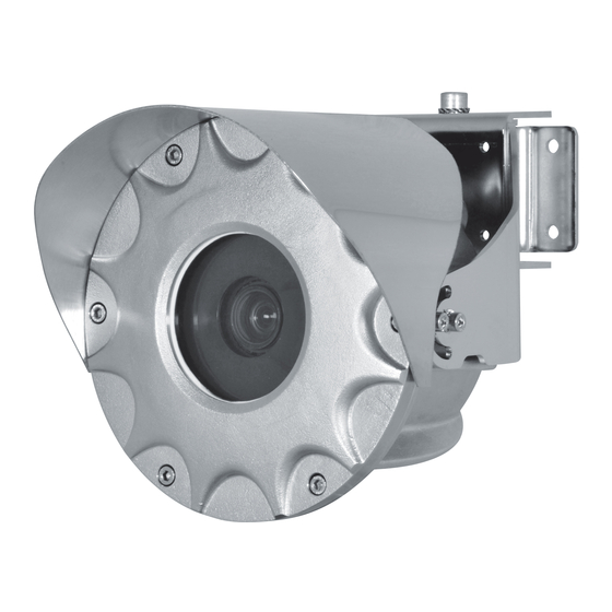
MAXIMUS MMX
Ex-proof FULL HD camera in a compact design
RU
PT
KO
Русский - Руководство по эксплуатации
Português - Manual de instruções
한국어 - 지침 설명서
M
a
anual
Kapitel
Fehlerbehebung

Verwandte Anleitungen für Videotec MAXIMUS MMX


Inhaltszusammenfassung für Videotec MAXIMUS MMX
- Seite 1 ENGLISH MAXIMUS MMX Ex-proof FULL HD camera in a compact design anual English - Instruction manual Italiano - Manuale di istruzioni Русский - Руководство по эксплуатации Français - Manuel d’instructions Português - Manual de instruções Deutsch - Bedienungsanleitung 한국어 - 지침 설명서...
- Seite 93 DEUTSCH MAXIMUS MMX Kompakte, explosionsgeschützte FULL HD-Kamera andbucH Deutsch - Bedienungsanleitung...
- Seite 95 Inhaltsverzeichnis D E U T S C H 1 Allgemeines ........................5 1.1 Schreibweisen ................................5 2 Anmerkungen zum Copyright und Informationen zu den Handelsmarken ..... 5 3 Sicherheitsnormen ......................5 3.1 Details der ATEX-IECEx-Bescheinigung ......................8 3.1.1 Temperatur ....................................8 3.1.2 Notwendige Eigenschaften installierbarer Videokameras ..................
- Seite 96 9.1.1 Inbetriebnahme ..................................24 9.1.2 Sicherheitsvorschriften ................................24 9.1.3 Vorschriften zur Vorbeugung von Explosionen ......................24 10 Einschaltung ......................25 10.1 Bevor man das Produkt in explosionsgefährdeten Bereichen versorgt ..........25 11 Wartung ........................25 11.1 Sicherung austauschen .............................26 11.2 Austausch der Dichtung des Frontdeckels ....................26 12 Reinigung ........................
-
Seite 97: Allgemeines
1 Allgemeines 3 Sicherheitsnormen Vor Installation und Anwendung der Einheit ist die ACHTUNG! Die externen Anschlüsse für den gesamte gelieferte Dokumentation aufmerksam zu Potenzialausgleich müssen mithilfe der Öse lesen. Zum späteren Nachschlagen das Handbuch in außen am Produkt vorgenommen werden. Reichweite aufbewahren. - Seite 98 • Die Anweisungen lesen. • Die Hauptisolierung muss produktextern mit einem Sicherheitstransformator und / oder einer • Die Anweisungen aufbewahren. isolierten Gleichspannungsquelle ausgeführt • Alle Hinweise beachten. werden. • Halten Sie sich an alle Anweisungen. • Zur Spannungsversorgung des • Um das Risiko eines Einschaltens zu verhindern, Produktes verwenden Sie bitte einen darf man das Gerät nicht bei potenziell Sicherheitstransformator und / oder eine isolierte...
- Seite 99 • Es dürfen keine Kabel mit Verschleiß- oder • Die nationalen Vorschriften für die Installation der Alterungsspuren verwendet werden. Einrichtung sind einzuhalten. • Unter keinen Umständen dürfen Veränderungen • Dies ist ein Produkt der Klasse A. Dieses Produkt oder Anschlüsse vorgenommen werden, die kann im Wohnbereich Funkstörungen verursachen.
-
Seite 100: Details Der Atex-Iecex-Bescheinigung
3.1 Details der ATEX-IECEx-Bescheinigung 3.1.1 Temperatur EINZELHEITEN DER MARKIERUNG Umgebungstemperatur Kennzeichnung ATEX Kennzeichnung IECEx -40°C to +65°C or +70°C II 2 G Ex db IIB T6...T5 Gb Ex db IIB T6...T5 Gb II 2 D Ex tb IIIC T85°C...T100°C Db Ex tb IIIC T85°C...T100°C Db Tab. -
Seite 101: Identifizierung
Atmosphären durch Gas, Dämpfe, Nebel M8x80 Schraube. oder Mischungen aus Luft oder Staub kommen kann. Sonnenschutzdach. Die Gehäuse MAXIMUS MMX sind aus rostfreiem Stahl AISI 316L. Sie sind oberflächenbehandelt und Gehäuse. somit korrosionsbeständiger. Die Kamera wird über einen Schlitten im Gehäuseinneren befestigt. -
Seite 102: Kennzeichnung Des Produkts
4.3 Kennzeichnung des Produkts Abb. 3 CE-Kennzeichnung und Nummer der benannten Stelle für die Überprüfung der Konformität der Produktion. Name und Adresse des Herstellers Identifizierungscode des Modells Umgebungsbetriebstemperatur Seriennummer (Die zweite und dritte Ziffer geben das Baujahr an) Versorgungsspannung (V) Stromaufnahme (A) Frequenz (Hz) Verbrauch von Kamera/Optik (W) -
Seite 103: Produktschlüssel
-40°C to +70°C Ex db IIB T5 Gb Ex tb IIIC T100°C Db Tab. 5 Im Gehäuse können zusätzliche Etiketten angebracht sein, die die Zeichen weiterer Zertifizierungen tragen. 5 Produktschlüssel MAXIMUS MMX - PRODUKTSCHLÜSSEL Spannung Kamera Anschluss Video Ausgang 2 24Vac/24Vdc, PoE+... -
Seite 104: Vorbereitung Des Produktes Auf Den Gebrauch
6 Vorbereitung des Bevor man irgendwelche Operationen Produktes auf den Gebrauch ausführt, muss sichergestellt werden, dass die Spannung der Leitung korrekt ist. Jede Art von Änderung, die nicht Das Handling erfordert keine besonderen ausdrücklich vom Hersteller gebilligt Vorkehrungen. Wir empfehlen daher dem wurde, lässt die Garantie und die zuständigen Personal, diese Operationen Zertifizierung verfallen. -
Seite 105: Entfernen Der Verpackung
6.2 Entfernen der Verpackung Der Installierende muss sicherstellen, dass zwischen dem installierten Produkt und Bei der Lieferung des Produktes ist zu prüfen, ob die der Anlage eine durchgängige Erdung Verpackung intakt ist oder offensichtliche Anzeichen vorhanden ist. von Stürzen oder Abrieb aufweist. Bei offensichtlichen Schadensspuren an der Das Produkt muss mit geeigneten Mitteln Verpackung muss umgehend der Lieferant... -
Seite 106: Befestigung An Der Brüstung Oder An Der Decke
6.5.1 Befestigung an der Brüstung oder an der Decke Das Produkt ist für die Montage am Geländer oder an der Decke geeignet. Die Befestigungshalterung (01) auf der Oberfläche des endgültigen Zielpunkts festmachen. Schrauben festziehen. Die Verstärkungshalterung (02) an die Gehäusehalterung (03) mit den im Lieferumfang enthaltenen M5-Schrauben und den 5 Unterlegscheiben montieren. -
Seite 107: Wandbefestigung
6.5.2 Wandbefestigung Das Produkt ist für die Wandmontage geeignet. Die Befestigungshalterung (01) auf der Oberfläche des endgültigen Zielpunkts festmachen. Schrauben festziehen. Die Gehäusehalterung (03) an der Befestigungshalterung (01) mit der M8-Schraube (05), den Unterlegscheiben und der Mutter montieren. Nachdem die Endposition des Produkts einmal festgelegt wurde, die M8-Schraube (05) mit Drehmoment festziehen und die M5-Schrauben (08) zum Blockieren der Rotation befestigen. -
Seite 108: Montageanleitungen
6.5.3 Montageanleitungen Die Achse der M8-Schraube muss sich immer in einer vertikalen Position befinden. Das Produkt kann in den nachfolgend angegebenen Positionen installiert werden. Abb. 15 Deckenmontage (Vertikale Drehung, -90°). Abb. 12 Wandmontage (Vertikale Drehung, -90°). Abb. 16 Deckenmontage (Vertikale Drehung, +30°). Abb. -
Seite 109: Zusammenbau
Position installiert werden. Die im Lieferumfang enthaltenen Halterungen müssen wie angegeben installiert werden( 6.5.3 Montageanleitungen, Seite 16). Abb. 17 Die installierbaren Videokameras dürfen keine Batterien enthalten. VIDEOTEC empfiehlt, vor der endgültigen Montage am Installationsort die Konfiguration und die Leistungen des Gerätes zu prüfen. MNVCMMX_1821_DE... -
Seite 110: Entfernen Des Schlittens
7.3 Entfernen des Schlittens 7.4 Beschreibung der Nachrüstungsplatine für den Die 3 M4 Kreuzschrauben lösen, um den Schlitten Video-Encoder zu entnehmen. Vor Entnahme des Schlittens, die Verkabelungen überprüfen, dass diese nicht mit der Schelle befestigt wurden. BESCHREIBUNG DER PLATINE Verbinder/ Funktion Klemme Stromversorgung/Videosignal (Kamera) -
Seite 111: Beschreibung Der Gehäuseplatine
7.5 Beschreibung der 7.6 Installation der Kamera Gehäuseplatine Die installierbaren Videokameras dürfen keine Batterien enthalten. BESCHREIBUNG DER PLATINE Verbinder/ Funktion Weitere Informationen zu den Klemme installierbaren Kameras können dem Stromversorgung (24Vac/24Vdc) entsprechenden Kapitel entnommen Heizung werden. (3.1.2 Notwendige Eigenschaften Platinentest installierbarer Videokameras, Seite 8). -
Seite 112: Installation
Alle Anschlüsse, die Installations- und Wartungseingriffe in nicht Die installierbaren Videokameras dürfen explosionsgefährdeten Bereichen keine Batterien enthalten. ausführen. VIDEOTEC empfiehlt, vor der endgültigen Sicherstellen, dass alle Geräte für den Montage am Installationsort die Gebrauch im Installationsraum zugelassen Konfiguration und die Leistungen des sind. -
Seite 113: Anschluss Der Gehäuseplatine
Stromversorgung Um das Produkt mit Strom zu versorgen, kann abgetrennt und die Trennvorrichtung offen VIDEOTEC als Zubehör einen 1 Kanal PoE Injector ist. liefern. Der PoE Injector muss in dem nicht klassifizierten Bereich oder in einem geeigneten Im Zuge der Installation ist zu prüfen,... -
Seite 114: Erdung
Das Ethernet-Netzkabel ist an den Ausgang Das Kabel für den Erdpotenzialausgleich mit dem zum „Ethernet, Versorgung PoE+“ anzuschließen (J8, 7.5 Lieferumfang gehörenden Ringkabelschuh verbinden. Beschreibung der Gehäuseplatine, Seite 19). Geeignet für Kabel:von 4mm² bis zu 6mm². Die Anschlüsse nach den Angaben in der Tabelle Die Öse mit der im Lieferumfang enthaltenen Schraube vornehmen (standardgerecht: TIA/EIA-568-B). -
Seite 115: Befestigung Des Dachs
8.5 Befestigung des Dachs Den Frontdeckel im Gehäusekorpus einsetzen. Hierzu die Verschlusslöcher zwischen Deckel und Korpus Das Produkt wird mit dem bereits installierten angleichen. Sonnenschutzdach geliefert. Darauf achten, die O-Ring-Dichtung nicht Zu Installationszwecken kann das zu beschädigen. Sonnenschutzdach abmontiert werden. Die Schrauben des Sonnenschutzdachs lösen Die zuvor entfernten Schrauben anschrauben. -
Seite 116: Anleitung Für Einen Sicheren Betrieb
Das vorliegende Gebrauchshandbuch vor der 9.1.3 Vorschriften zur Vorbeugung von Installation aufmerksam und vollständig durchlesen. Explosionen VIDEOTEC empfiehlt, vor der endgültigen Montage am Installationsort die Konfiguration Entsprechendes Werkzeug für die Eingriffe in der und die Leistungen des Gerätes zu prüfen. Dazu jeweiligen Zone verwenden. -
Seite 117: Einschaltung
Kontakt mit vorschriftsgemäß von entsprechend unter Spannung stehenden Bauteilen zu ausgebildetem Personal oder unter der verhindern. Aufsicht von Personal der Firma VIDEOTEC ausgeführt werden: IEC/EN60079-19. Sicherstellen, dass das Gerät gemäß der Anweisungen im Handbuch an einer Im Falle von Beschädigungen muss Erdungsleitung angeschlossen ist. -
Seite 118: Sicherung Austauschen
Dichtung ersetzt Für jegliche Wartungsarbeiten wird werden. Als Ersatz für die mitgelieferte Dichtung empfohlen, das Produkt für die dürfen nur originale Ersatzteile von VIDEOTEC notwendigen Arbeiten in die Werkstatt zu verwendet werden. bringen. Die Dichtung auswechseln und dabei darauf achten, Wenn der Kundendienst von VIDEOTEC kontaktiert sie korrekt im vorgesehenen Sitz einzufügen. -
Seite 119: Reinigung
12 Reinigung 14 Problemlösung Die Häufigkeit der Eingriffe hängt von der Kontaktieren Sie bitte das autorisierte Umgebung ab, in der die Einheit verwendet Kundenzentrum bei jedem nicht wird. beschriebenen Problem oder falls das aufgelistete Problem weiterhin bestehen 12.1 Reinigung des Glases sollte. -
Seite 120: Elektrik
15.4 Elektrik 15.7 Kamera Versorgungsspannung/Stromaufnahme Leistungsaufnahme (Videokamera und Optik): • 24Vac, 1.32A, 50/60Hz • Vorinstallierter Video-Encoder: 4.5W • 24Vdc, 0.9A • In die Kamera eingebauter Video-Encoder: 5.8W • PoE+ (IEEE 802-at) Abmessungen der Kameras/Einsetzbare Objektive (WxHxL): 52mmx52mmx78mm Leistungsaufnahme: 15.8 Umgebung •... -
Seite 121: Technische Zeichnungen
16 Technische Zeichnungen Die Maße sind in Millimetern angegeben. BEFESTIGUNG AN DER WAND BEFESTIGUNG AN DER BRÜSTUNG ODER AN DER DECKE Abb. 30 MAXIMUS MMX. MNVCMMX_1821_DE...