Herunterladen Inhalt Inhalt Diese Seite drucken

Videotec MAXIMUS MPXHD Bedienungsanleitung

Ex-geschützte full-hd ptz kamera
Vorschau ausblenden Andere Handbücher für MAXIMUS MPXHD:
Inhaltsverzeichnis

Werbung

Verfügbare Sprachen
  • DE

Verfügbare Sprachen

  • DEUTSCH, seite 149
ITALIANO
EN
English - Instruction manual
IT
Italiano - Manuale di istruzioni
FR
Français - Manuel d'instructions
DE
Deutsch - Bedienungsanleitung
MAXIMUS MPXHD
Explosion-proof Full HD PTZ camera
RU
Русский - Руководство по эксплуатации
PT
Português - Manual de instruções
KO
한국어 - 지침 설명서

Werbung

Inhaltsverzeichnis
loading

Inhaltszusammenfassung für Videotec MAXIMUS MPXHD

  • Seite 1 ITALIANO MAXIMUS MPXHD Explosion-proof Full HD PTZ camera English - Instruction manual Italiano - Manuale di istruzioni Русский - Руководство по эксплуатации Français - Manuel d’instructions Português - Manual de instruções 한국어 - 지침 설명서 Deutsch - Bedienungsanleitung...
  • Seite 3 ENGLISH MAXIMUS MPXHD Explosion-proof Full HD PTZ camera English - Instruction manual...
  • Seite 5: Inhaltsverzeichnis

    Contents E N G L I S H 1 About this manual ......................7 1.1 Typographical conventions ..........................7 2 Notes on copyright and information on trademarks ..........7 3 Safety rules........................7 4 Identification ........................9 4.1 Product description and type designation..................... 9 4.2 Product marking ..............................10 5 Preparing the product for use ..................
  • Seite 6 9.1 Software interface ..............................25 9.1.1 Minimum system requirements ............................25 9.1.2 Configuration procedure through software ........................25 9.1.3 Installing the software .................................26 9.2 Web interface ................................28 9.2.1 Home Page ....................................28 9.2.2 User Controls page ................................28 9.2.3 Device Parameters Page ..............................29 9.2.4 Device Statistics page ................................29 9.2.5 Network Configuration page ............................30 9.2.6 User Configuration page ..............................30 9.2.7 Movement Parameters page .............................31...
  • Seite 7 14 Technical drawings ....................43 A Appendix - Marking codes ..................44 A.1 ATEX marking ................................44 A.2 IECEx marking .................................45 A.3 Gas group classification ............................46 B Appendix - Flamepath ....................47 MNVCMPXHD_1801_EN...
  • Seite 8 MNVCMPXHD_1801_EN...
  • Seite 9: About This Manual

    1 About this manual 3 Safety rules Read all the documentation supplied carefully before CAUTION! This device must be connected installing and using this unit. Keep the manual in a to an earth conductor (protective earth). convenient place for future reference. This connection must only be performed through the power line connector (J1, 1.1 Typographical conventions...
  • Seite 10 • Read these instructions. • This device is remotely controlled and may change position at any time. It should be installed so that • Keep these instructions. no one can be hit by moving parts. It should be • Heed all warnings. installed so that moving parts cannot hit other •...
  • Seite 11: Identification

    4 Identification MAXIMUS MPXHD PTZ offers continuous, high speed rotation, positioning precision and superior image quality, utmost sturdiness and simplified system 4.1 Product description and type configuration. designation Speed and precision are the predominant pan-and- tilt characteristics, reaching 100°/s in continuous The MAXIMUS MPXHD series explosion-proof pan- horizontal rotation, with vertical range between -90°...
  • Seite 12: Product Marking

    4.2 Product marking Fig. 3 CE symbol 10. ATEX certification: Manufacturer’s name and address • ATEX certificate number Model identification code • Classification for zone type, protection method, temperature class for which this product may be Ambient temperature of use referring to model used in compliance with the ATEX directive identification code 11.
  • Seite 13: Preparing The Product For Use

    5 Preparing the product for The device can only be considered to be switched off when the power supply has been disconnected and the connection cables to other devices have been removed. Any change that is not expressly approved by the manufacturer will invalidate both Make connections and tests in the the guarantee and certification.
  • Seite 14: Safely Disposing Of Packaging Material

    5.3 Contents 5.4 Safely disposing of packaging material Check the contents to make sure they correspond with the list of materials as below: The packaging material can all be recycled. The • 1 explosion-proof P&T installer technician will be responsible for separating the material for disposal, and in any case for •...
  • Seite 15: Preparatory Work Before Installation

    5.5 Preparatory work before 5.5.1 Fixing to parapet or ceiling mount installation Attach the adapter (01) to the bottom of the unit using 4 stainless steel (A4 class 70) socket flat head cap screw M10 x 20mm (02). Use appropriate tools for the installation. The particular nature of the site where the Make sure the thread are free of dirt and debris.
  • Seite 16: Bracket Mounting

    5.5.2 Bracket mounting 5.5.3 Fixing the unit to the pole mount adapter or corner mount adapter The bracket can be fixed to the vertical wall. Use screws and wall fixing devices that can bear at least To install the product on a pole or at a wall corner, four times the weight of the unit.
  • Seite 17: Fixing With Corner Adapter

    5.5.3.2 Fixing with corner adapter 5.5.4 Sunshield mounting Fix the wall bracket to the corner mount adapter Remove the protective film before the using 4 washers, 4 stainless steel grower washers sunshield installation. 4 hexagon stainless steel bolts (A4 class 70) M10x30mm.
  • Seite 18: Installation

    6.2 Methods of installation with local regulations and specifications. The system can be installed only in a standard or VIDEOTEC strongly recommend to test the device inverted position (ceiling mount). When installed configuration and performance before putting it in for inverted operation, the camera orientation and the final installation site (6.3 Connection of the cables...
  • Seite 19: Connection Of The Cables To The Base

    6.3 Connection of the cables to A connection compartment for cable entry with a 3/4” NPT threaded hole is located on the base of the the base unit. A threaded cap gives access to a connection board CAUTION! The electrical system to which the with removable connectors that help the installer to unit is connected must be equipped with a connect the cables.
  • Seite 20: Connector Board Description

    6.4 Connector board description 6.5 Cable entry BOARD DESCRIPTION The telemetry line is not required for normal functioning of the device. Connector/Ter Function minal To prevent the spread of flames or explosions from Power supply line the unit to the conduit system or cable gland to the Relay, alarms external environment, use connection in conformity Serial line...
  • Seite 21: Connection Of The Power Supply Line

    6.6 Connection of the power All signal cables must be grouped together supply line by means of a cable tie. Depending on the version, the device can be The power cables must be sized according to the provided with different power supply voltages. The ratio between the supply current and the distance to power supply voltage is indicated on the product be covered.
  • Seite 22: Connection Of The Ethernet Cable

    6.7 Connection of the Ethernet 6.8 Alarm and relay connections cable Identify the relay and alarm terminal and the serial line terminal on the board (J3, J9, 6.4 Connector During the wiring do not connect cable RS- board description, page 18). 485 and the video cable.
  • Seite 23: Connecting An Alarm With Dry Contact

    6.8.1 Connecting an alarm with dry 6.8.3 Washing system connection contact For further details on configuration and For a dry contact alarm (alarm AL1), implement the use, refer to the relative manual. connection as shown in the figure. When the washing system is enabled, the relay is used exclusively for the activation of the pump (9.2.12 Washer page, page 33).
  • Seite 24: Connection Compartment Closing

    The device could be no longer safe for the installation on a potentially explosive atmosphere. In this case contact VIDEOTEC technical support. The O-ring must be replaced by a new one after each opening. Verify that there is no dirt or debris.
  • Seite 25: Instructions For Safe Operation

    Installation of the electrical equipment must comply before starting the installation. with the local legislation in force. VIDEOTEC strongly recommend to test the device The device must be installed only and exclusively by configuration and performance before putting it in qualified technical personnel.
  • Seite 26: Switching On

    8 Switching on 8.1 Before powering the product in an explosive atmosphere The automatic pre-heating (De-Ice) process could be started whenever the device is Make sure that the unit and other switched on and the ambient temperature components of the installation are closed is below 0°C (+32°F).
  • Seite 27: Configuration

    Internet Explorer® 6.0). Fig. 21 The product can work via ONVIF or TCAM (VIDEOTEC) protocol. In the event the ONVIF protocol is used, make sure to set the time correctly in the device or to configure an NTP server. (9.2.5 Network Configuration page, page 30).
  • Seite 28: Installing The Software

    9.1.3 Installing the software Assign a name to the camera and to the unit. Select the ONVIF or TCAM protocol and set the device's Insert the CD and start the autoplay or launch the IP address and the access credentials. Select the installer.
  • Seite 29 To display the cameras on different computers, install Once the server has been added it must be registered the TVMS client and use it to connect to the TVMS to display it. Drag the server icon on the right column server in remote.
  • Seite 30: Web Interface

    9.2 Web interface 9.2.2 User Controls page To control the device through the browser, select the During the first connection assign an User Control entry. A new window will open with a address other than 192.168.10.100. virtual keyboard to enter commands. Browsers supported: Microsoft Internet Explorer, Microsoft Edge, Google Chrome, Mozilla Firefox.
  • Seite 31: Device Parameters Page

    9.2.3 Device Parameters Page • Focus Near/Focus Far In the Device Settings menu, it is possible to view the information on the product code, the serial number, the MAC address, the firmware version and the hardware review. Fig. 33 • Wiper/Washer: If a tank was installed and configured, the command activates the wiper and the wash procedure.
  • Seite 32: Network Configuration Page

    9.2.5 Network Configuration page NTP Server: It is also possible to specify if the device needs to be synchronised with an external NTP From menu entry it is possible to change the network (Network Time Protocol) server. setting of product. It is possible to decide whether •...
  • Seite 33: Movement Parameters Page

    9.2.7 Movement Parameters page • Tilt Limits: Enables the limits of Tilt. • Tilt Start: Sets the start limit of Tilt. From menu entry Movement Parameters it is possible to control, via web, all Pan & Tilt parameters. • Tilt End: Sets the end limit of Tilt. •...
  • Seite 34: Patrol Page

    9.2.7.2 Patrol Page • Speed of Movements Default: The speed used in autopan and patrol operations. From menu entry Patrol it is possible to specify the • Impose Default Speed: The default speed will also preset patrol start and end. Patrol is a function that be set as the scanning speed for all presets.
  • Seite 35: Digital I/O Page

    9.2.10 Digital I/O Page 9.2.13 Encoder Parameters page From menu entry Digital I/O it is possible to configure In the Encoder Settings menu, it is possible to the digital channels available in the device. What configure up to 4 video flows of the device. The first follows is a brief description of the configurable flow must be compressed with the algorithm H.264/ parameters for each digital input.
  • Seite 36: Camera Settings Page

    9.2.14 Camera Settings page • Other: It allows setting other values: Image Mirror, Noise Reduction, Wide Dynamic (Visibility The camera integrated in the device can be Enhancer), High Resolution, Aperture Control, configured under the Camera Parameters menu: Defog, Highlight Correction. •...
  • Seite 37: Directional Osd Page

    9.2.15 Directional OSD Page The device supports definition of four pan regions Start and information text video display based on the position of the Pan & Tilt. The four areas can be 0° overlapped. You can define the following settings for each area: •...
  • Seite 38: Video Analysis Page

    9.2.16 Video Analysis Page 9.2.18 Factory Default The device can be configured to emit motion Before doing any technical work or detection alarms using ONVIF events. maintenance on the device, make sure that This page allows you to define the following settings: potentially explosive atmosphere is not present.
  • Seite 39: Special Controls

    9.3 Special controls SPECIAL CONTROLS Action Command Protocol TCAM ONVIF (auxiliary command) Wiper Start Save Preset 85 tt:Wiper|On Wiper Stop Save Preset 86 tt:Wiper|Off Washer Save Preset 87 tt:Washing Procedure|On Night Mode On Save Preset 88 tt:IRLamp|On Night Mode Off Save Preset 89 tt:IRLamp|Off Reboot the device...
  • Seite 40: Maintenance

    Whenever replacing the parts as indicated, 120Vac, 50/60Hz T 2A H 250V 5x20 T 4A H 250V 5x20 always use VIDEOTEC original spare parts 230Vac, 50/60Hz T 1A L 250V 5x20 T 4A H 250V 5x20 and meticulously follow the maintenance Tab.
  • Seite 41: Information On Disposal And Recycling

    12 Troubleshooting This product must only be repaired by suitably trained personnel or under the supervision of VIDEOTEC personnel in accordance with the foreseen terms and conditions: IEC/EN60079-19. Contact an authorized support centre if the problems listed below persist or you have any other issues that are not described here.
  • Seite 42: Technical Data

    13 Technical data 13.4 Network Ethernet connection: 10BASE-T/100BASE-T 13.1 General Connector: RJ45 AISI 316L stainless steel construction Cable length: 100m max Passivated and electropolished external surfaces 13.5 Video Dynamic positioning control system Video encoder 13.2 Mechanical • Communication protocol: ONVIF, Profile S 1 3/4"...
  • Seite 43: Cameras

    13.7 Cameras Focus System: Auto (Sensitivity: Normal, Low), One- push AF, Manual, Focus compensation with ICR On, Day/Night Full HD 30x Interval AF, Zoom trigger AF Resolution: Full HD 1080p (1920x1080pixel) Picture Effects: E-flip, Mirror image, Color enhancement Image Device: 1/2.8 type Exmor™ CMOS sensor Exposure Control: Auto, EV Compensation, Manual, Effective Pixels: approx.
  • Seite 44: Electrical Rating

    13.10 Electrical rating ELECTRICAL RATING Supply voltage Normal usage to be specified on product label Short term de-icing cicle. Peak maintaining a minimum internal temp at 5°C 230Vac 0.11A, 50/60Hz, 25.3W 0.52A, 50/60Hz, 120W 24Vac 1.08A, 50/60Hz, 25.9W 5A, 50/60Hz, 120W 120Vac 0.21A, 50/60Hz, 25.2W 1A, 50/60Hz, 120W...
  • Seite 45: Technical Drawings

    14 Technical drawings The measurements indicated are expressed in millimetres. Ø 138 N°4 M10 Fig. 57 MAXIMUS MPXHD. MNVCMPXHD_1801_EN...
  • Seite 46: A Appendix - Marking Codes

    EN - English - Instruction manual A Appendix - Marking codes A.1 ATEX marking 2 G Ex db ÐÐC T6 Gb T -40°C to +60°C ÏÐÐ ÐÐ 2 D Ex tb ÐÐÐC T85°C Db T -40°C to +60°C Ï IP66 Fig.
  • Seite 47: Iecex Marking

    A.2 IECEx marking Ex db eeC T6 Gb T -40°C to +60°C Ex tb eeeC T85°C Db T -40°C to +60°C IP66 Fig. 59 Ex db ÐÐC Tfi -40°C to +60°C Ex-proof housing for potentially Gas group Gas temperature classification Protection level of the equipment Installation temperature range explosive environments...
  • Seite 48: Gas Group Classification

    A.3 Gas group classification The table below shows the classification of some gases and vapours, according to the explosion-proof protection group and the temperature class. For a complete list see IEC/EN60079-12 and IEC/EN60079-20. GAS GROUP CLASSIFICATION Temperature class (Maximum surface temperature of the housing) 1 Class 450°C (842°F) 300°C (572°F)
  • Seite 49: B Appendix - Flamepath

    B Appendix - Flamepath The maximum constructional gap (ic) is less than that required by Table 3 of EN 60079-1:2014 as detailed below: FLAMEPATH MAXIMUM GAP (MM) MINIMUM WIDTH (MM) COMMENT Between component drawings 0.249 25.4 Cylindrical joint sup- BRT2MPXALBPAN-EX e BRT2MPXTAPINF-EX ported by bearings Between component drawings 0.245...
  • Seite 50 Email: info@videotec.com Tel. +33 1 60491816 - Fax +33 1 69284736 Email: info.fr@videotec.com Asia Pacific Videotec (HK) Ltd Americas Videotec Security, Inc. Flat 8, 19/F. On Dak Industrial Building, No. 2-6 Wah Sing Street Gateway Industrial Park, 35 Gateway Drive, Suite 100 Kwai Chung, New Territories - Hong Kong Plattsburgh, NY 12901 - U.S.A.
  • Seite 51 ITALIANO MAXIMUS MPXHD Telecamera PTZ Full HD antideflagrante Italiano - Manuale di istruzioni...
  • Seite 53 Sommario I T A L I A N O 1 Informazioni sul presente manuale ................7 1.1 Convenzioni tipografiche ............................. 7 2 Note sul copyright e informazioni sui marchi commerciali ........7 3 Norme di sicurezza ......................7 4 Identificazione ....................... 9 4.1 Descrizione e designazione del prodotto .......................
  • Seite 54 9.1 Interfaccia software ..............................25 9.1.1 Requisiti minimi del PC ................................25 9.1.2 Procedura di configurazione tramite software ......................25 9.1.3 Installazione del software ..............................26 9.2 Interfaccia web ...............................28 9.2.1 Pagina Home ...................................28 9.2.2 Pagina Controlli Utente ...............................28 9.2.3 Pagina Parametri Dispositivo ............................29 9.2.4 Pagina Statistiche Dispositivo ............................29 9.2.5 Pagina Configurazione Rete ..............................30 9.2.6 Pagina Configurazione Utenti ............................30...
  • Seite 55 14 Disegni tecnici ......................43 A Appendice - Codifica della marcatura................ 44 A.1 Marcatura ATEX ..............................44 A.2 Marcatura IECEx ..............................45 A.3 Classificazione Gruppi Gas ..........................46 B Appendice - Percorso di fiamma ................47 MNVCMPXHD_1801_IT...
  • Seite 56 MNVCMPXHD_1801_IT...
  • Seite 57: Informazioni Sul Presente Manuale

    1 Informazioni sul presente 3 Norme di sicurezza manuale ATTENZIONE! L’apparecchio deve essere collegato a un conduttore di terra (messa Prima di installare e utilizzare questa unità, leggere a terra protettiva). Tale collegamento attentamente tutta la documentazione fornita. Tenere deve essere eseguito solo attraverso il il manuale a portata di mano per consultazioni connettore della linea di alimentazione (J1, successive.
  • Seite 58 • Leggere le istruzioni. • L’apparecchio è controllato a distanza e può pertanto cambiare posizione in qualsiasi • Conservare le istruzioni. momento. Installare l’apparecchio in modo da • Osservare tutte le avvertenze. evitare incidenti causati dal contatto con parti • Attenersi a tutte le istruzioni. in movimento, facendo sì...
  • Seite 59: Identificazione

    4 Identificazione MAXIMUS MPXHD PTZ offre una rotazione continua ad alta velocità, precisione di posizionamento e qualità delle immagini superiore abbinate alla 4.1 Descrizione e designazione massima solidità e a una configurazione di sistema del prodotto semplificata. La velocità e la precisione sono le caratteristiche...
  • Seite 60: Marcatura Del Prodotto

    4.2 Marcatura del prodotto Fig. 3 Simbolo CE 10. Certificazione ATEX: Nome e indirizzo del costruttore • Numero di certificato ATEX Codice di identificazione del modello • Classificazione del tipo di zona, metodo di protezione, classe di temperatura per le quali è Temperatura ambiente di utilizzo riferita al ammesso l’impiego di questo prodotto secondo codice di identificazione del modello...
  • Seite 61: Preparazione Del Prodotto Per L'utilizzo

    5 Preparazione del prodotto L’apparecchio si considera disattivato per l'utilizzo soltanto quando l’alimentazione è disinserita e i cavi di collegamento con altri dispositivi sono stati rimossi. Qualsiasi intervento non espressamente approvato dal costruttore fa decadere la Effettuare i collegamenti e prove in garanzia e la certificazione.
  • Seite 62: Smaltimento In Sicurezza Dei Materiali Di Imballaggio

    5.3 Contenuto 5.4 Smaltimento in sicurezza dei materiali di imballaggio Controllare che il contenuto sia corrispondente alla lista del materiale sotto elencato: I materiali d'imballo sono costituiti interamente da • 1 brandeggio antideflagrante materiale riciclabile. Sarà cura del tecnico installatore smaltirli secondo le modalità...
  • Seite 63: Lavoro Preparatorio Prima Dell'installazione

    5.5 Lavoro preparatorio prima 5.5.1 Fissaggio a parapetto o a soffitto dell’installazione Collegare l’adattatore (01) al fondo dell’unità utilizzando 4 viti a testa svasata piana (02) con esagono incassato M10x20mm in acciaio inox (A4 Eseguire l’installazione utilizzando utensili classe 70). adeguati.
  • Seite 64: Fissaggio Con Staffa

    5.5.2 Fissaggio con staffa 5.5.3 Fissaggio con imbracatura da palo o modulo adattatore angolare Il supporto può essere fissato direttamente ad un muro verticale. Utilizzare viti e dispositivi di fissaggio Per installare il prodotto su imbracatura da palo o in a muro che possono sostenere un peso almeno 4 corrispondenza di un angolo prima di tutto fissare volte superiore a quello dell’unità.
  • Seite 65: Fissaggio Con Modulo Angolare

    5.5.3.2 Fissaggio con modulo angolare 5.5.4 Fissaggio del tettuccio Per fissare la staffa di supporto a muro al modulo Prima di fissare il tettuccio della custodia adattatore angolare, utilizzare 4 rondelle piane, rimuovere la pellicola protettiva. 4 rondelle grower in acciaio inox e 4 viti a testa esagonale in acciaio inox (A4 classe 70) da Fissare il tettuccio alla custodia utilizzando viti e M10x30mm.
  • Seite 66: Installazione

    L'unità può essere installata solamente in posizione standard o invertita (montaggio a VIDEOTEC raccomanda di testare la configurazione e soffitto). Se installata in quest’ultima posizione, la le prestazioni dell’apparecchio prima di collocarlo nel riconfigurazione delle funzioni di orientamento sito di installazione definitivo (6.3 Collegamento dei...
  • Seite 67: Collegamento Dei Cavi Alla Base

    6.3 Collegamento dei cavi alla Sulla base dell’unità è presente un vano connessioni con foro filettato da 3/4” NPT per l’ingresso dei cavi. base Svitando il coperchio filettato si accede a una scheda di connettori dotata di connettori rimovibili ATTENZIONE! L’impianto elettrico al quale che facilitano il collegamento dei cavi durante è...
  • Seite 68: Descrizione Della Scheda Connettori

    6.4 Descrizione della scheda 6.5 Ingresso cavi connettori La linea di telemetria non è necessaria per il normale funzionamento del dispositivo. DESCRIZIONE DELLA SCHEDA Connettore/Mo Funzione Per prevenire la propagazione di fiamme o esplosioni rsetto dal dispositivo al sistema conduit o pressacavo, e Linea di alimentazione da quest’ultimi all’ambiente esterno, eseguire una connessione conforme alla norma IEC/EN60079-14.
  • Seite 69: Collegamento Della Linea Di Alimentazione

    6.6 Collegamento della linea di Tutti i cavi di segnale devono essere alimentazione raggruppati con una fascetta. A seconda della versione, al dispositivo possono I cavi di alimentazione dovranno essere dimensionati essere fornite diverse tensioni di alimentazione. in base al rapporto tra la corrente di alimentazione e Il valore di tensione di alimentazione è...
  • Seite 70: Collegamento Del Cavo Di Rete Ethernet

    6.7 Collegamento del cavo di rete 6.8 Collegamento degli allarmi e Ethernet dei relè Individuare sulla scheda il morsetto dei relè e allarmi Durante le operazioni di cablaggio non e il morsetto della linea seriale (J3, J9, 6.4 Descrizione collegare il cavo RS-485 e il cavo video. della scheda connettori, pagina 18).
  • Seite 71: Collegamento Allarme Con Contatto Pulito

    6.8.1 Collegamento allarme con 6.8.3 Collegamento dell'impianto di contatto pulito lavaggio Nel caso di allarme a contatto pulito (allarme AL1), Per ulteriori dettagli sulla configurazione eseguire il collegamento come illustrato in figura. e l’utilizzo fare riferimento al manuale del relativo accessorio. Quando l'impianto di lavaggio viene abilitato, il relè...
  • Seite 72: Chiusura Del Vano Connessioni

    In questo caso rivolgersi al servizio tecnico di VIDEOTEC. Ad ogni apertura l'O-ring deve essere sostituito con uno nuovo. Verificare che non vi sia la presenza di sporcizia o residui.
  • Seite 73: Istruzioni Di Funzionamento In Sicurezza

    L’installazione dell’apparecchio deve essere eseguita manuale d’uso prima di procedere con l’installazione. esclusivamente da personale specializzato. VIDEOTEC raccomanda di testare la configurazione e le prestazioni dell’apparecchio prima di collocarlo nel 7.1.3 Prescrizioni di prevenzione delle sito di installazione definitivo. Utilizzare degli utensili esplosioni adeguati.
  • Seite 74: Accensione

    8 Accensione 8.1 Prima di alimentare il prodotto in atmosfera esplosiva La procedura di preriscaldamento automatico (De-Ice) si potrebbe attivare Assicurarsi che l'unità e gli altri componenti tutte le volte che il dispositivo viene acceso dell’impianto siano chiusi in modo idoneo a ad una temperatura ambiente inferiore impedire il contatto con componenti sotto a 0°C.
  • Seite 75: Configurazione

    Microsoft Internet Explorer® 6.0 o superiore. Fig. 21 Il prodotto può funzionare mediante protocollo ONVIF o TCAM (VIDEOTEC). Se si utilizza il protocollo ONVIF, assicurarsi di impostare l'ora correttamente nel dispositivo o di configurare un server NTP ( 9.2.5 Pagina Configurazione Rete, pagina...
  • Seite 76: Installazione Del Software

    9.1.3 Installazione del software Assegnare un nome alla telecamera ed al gruppo. Selezionare il protocollo ONVIF o TCAM e impostare Inserire il CD ed avviare l'autoplay o lanciare l'indirizzo IP del dispositivo e le credenziali di accesso. l'installer. Si aprirà una pagina web che permetterà Selezionare i profili di streaming ed assicurarsi che la l'installazione delll'applicazione TVMS server (32 o 64 voce Use PTZ sia abilitata.
  • Seite 77 Per visualizzare le telecamere su più computer è Dopo aver aggiunto il server sarà necessario necessario installare il TVMS client ed utilizzarlo per registrarlo per la visualizzazione. Trascinare l'icona del collegarsi in remoto al TVMS server. Per configurare il server sulla colonna di destra come illustrato in figura. client, accedere con le credenziali di default.
  • Seite 78: Interfaccia Web

    9.2 Interfaccia web 9.2.2 Pagina Controlli Utente Per controllare il dispositivo via browser, selezionare Alla prima connessione assegnare un la voce Controlli Utente. Si aprirà una nuova finestra indirizzo diverso da 192.168.10.100. con una tastiera virtuale per inviare i comandi. Browser supportati: Microsoft Internet Explorer, Microsoft Edge, Google Chrome, Mozilla Firefox.
  • Seite 79: Pagina Parametri Dispositivo

    9.2.3 Pagina Parametri Dispositivo • Focus Near/Focus Far Alla voce del menù Parametri Dispositivo è possibile visualizzare le informazioni sul codice prodotto, il numero di serie, l'indirizzo MAC, la versione dei firmware e la revisione dell'hardware. Fig. 33 • Wiper/Washer: Se è stata installata e configurata una tanica, il comando aziona il tergicristallo e la procedura di lavaggio.
  • Seite 80: Pagina Configurazione Rete

    9.2.5 Pagina Configurazione Rete Server NTP: È possibile inoltre specificare se il dispositivo debba sincronizzarsi con un server NTP Alla voce del menù è possibile cambiare (Network Time Protocol) esterno. l'impostazione di rete del prodotto. È possibile • DISABILITATO: Selezionare questa opzione se non decidere se il dispositivo debba avere un indirizzo si desidera sincronizzare data e ora del dispositivo.
  • Seite 81: Pagina Parametri Movimento

    9.2.7 Pagina Parametri Movimento • Limiti Tilt: Abilita i limiti del Tilt. • Tilt Inizio: Imposta il limite iniziale del Tilt. Alla voce del menù Parametri Movimento è possibile controllare via web tutti i parametri del brandeggio. • Tilt Fine: Imposta il limite finale del Tilt. •...
  • Seite 82: Pagina Patrol

    9.2.7.2 Pagina Patrol • Velocità Movimenti Default: La velocità usata nelle operazioni di autopan e patrol. Alla voce del menù Patrol è possibile specificare • Imponi Velocità di Default: La velocità di default il preset di inizio e di fine del patrol. Patrol è una verrà...
  • Seite 83: Pagina I/O Digitali

    9.2.10 Pagina I/O Digitali 9.2.13 Pagina Parametri Encoder Alla voce del menù I/O Digitali è possibile configurare Alla voce del menù Parametri Encoder è possibile i canali digitali presenti nel dispositivo. Segue una configurare fino a 4 flussi video del dispositivo. Il breve descrizione dei parametri configurabili per primo flusso è...
  • Seite 84: Pagina Parametri Telecamera

    9.2.14 Pagina Parametri Telecamera • Altro: Permette di impostare altri valori: Immagine Speculare, Riduzione Rumore, Wide Dynamic Alla voce del menù Parametri Camera è possibile (Visibility Enhancer), Alta Risoluzione, Controllo configurare la telecamera integrata nel dispositivo: Apertura, Defog, Correzione Sovraesposizione. •...
  • Seite 85: Pagina Osd Direzionale

    9.2.15 Pagina OSD Direzionale Il dispositivo supporta la definizione di quattro Start regioni pan e la visualizzazione a video di testo informativo in base alla posizione del brandeggio. Le 0° quattro aree possono essere sovrapposte. È possibile definire per ogni area i seguenti parametri: •...
  • Seite 86: Pagina Analisi Video

    9.2.16 Pagina Analisi Video 9.2.18 Factory Default Il dispositivo può essere configurato affinché emetta Prima di effettuare interventi tecnici degli allarmi di motion detection mediante eventi sull’apparecchio, assicurarsi che non ONVIF. sia presente atmosfera potenzialmente In questa pagina è possibile definire i seguenti esplosiva.
  • Seite 87: Comandi Speciali

    9.3 Comandi speciali COMANDI SPECIALI Azione Comando Protocollo TCAM ONVIF (auxiliary command) Wiper Start Salvare Preset 85 tt:Wiper|On Wiper Stop Salvare Preset 86 tt:Wiper|Off Washer Salvare Preset 87 tt:Washing Procedure|On Modalità Notturna On Salvare Preset 88 tt:IRLamp|On Modalità Notturna Off Salvare Preset 89 tt:IRLamp|Off Reboot dispositivo...
  • Seite 88: Manutenzione

    In caso di danneggiamento la sostituzione Tensione di Fusibile (FUS1) Fusibile (FUS2) o riparazione delle parti interessate deve alimentazione essere eseguita da VIDEOTEC o sotto la sua 24Vac, 50/60Hz T 4A H 250V 5x20 T 4A H 250V 5x20 supervisione. 120Vac, 50/60Hz...
  • Seite 89: Informazioni Sullo Smaltimento E Il Riciclo

    12 Risoluzione dei problemi La riparazione di questo prodotto deve essere eseguita da personale adeguatamente addestrato o con la supervisione del personale VIDEOTEC in conformità alla norme previste: IEC/ EN60079-19. Per qualunque problematica non descritta o se i problemi elencati di seguito dovessero persistere, contattare il centro di assistenza autorizzato.
  • Seite 90: Dati Tecnici

    13 Dati tecnici 13.4 Rete Connessione Ethernet: 10BASE-T/100BASE-T 13.1 Generale Connettore: RJ45 Costruzione in acciaio Inox AISI 316L Lunghezza del cavo: 100m max Superfici esterne passivate ed elettrolucidate 13.5 Video Sistema dinamico di controllo della posizione Encoder video 13.2 Meccanica •...
  • Seite 91: Telecamere

    13.7 Telecamere Sistema Focus: Auto (Sensibilità: Normale, Bassa), AF singolo, Manuale, Focus compensation in ICR On, Day/Night Full HD 30x Intervallo AF, Zoom trigger AF Risoluzione: Full HD 1080p (1920x1080pixel) Effetti immagine: E-flip, Immagine specchiata, Miglioramento del colore Sensore di immagine: 1/2.8 type Exmor™ CMOS sensor Controllo Esposizione: Auto, EV Compensation, Manuale, Priorità...
  • Seite 92: Consumo Elettrico

    13.10 Consumo elettrico CONSUMO ELETTRICO Tensione di Normale utilizzo da specificare nella targhetta di Massimo consumo durante la procedura di preriscal- alimentazione marcatura damento automatico (De-Ice) per mantenere una temperatura minima interna 5°C 230Vac 0.11A, 50/60Hz, 25.3W 0.52A, 50/60Hz, 120W 24Vac 1.08A, 50/60Hz, 25.9W 5A, 50/60Hz, 120W...
  • Seite 93: Disegni Tecnici

    14 Disegni tecnici Le misure indicate sono espresse in millimetri. Ø 138 N°4 M10 Fig. 57 MAXIMUS MPXHD. MNVCMPXHD_1801_IT...
  • Seite 94: A Appendice - Codifica Della Marcatura

    IT - Italiano - Manuale di istruzioni A Appendice - Codifica della marcatura A.1 Marcatura ATEX 2 G Ex db ÐÐC T6 Gb T -40°C to +60°C ÏÐÐ ÐÐ 2 D Ex tb ÐÐÐC T85°C Db T -40°C to +60°C Ï...
  • Seite 95: Marcatura Iecex

    A.2 Marcatura IECEx Ex db eeC T6 Gb T -40°C to +60°C Ex tb eeeC T85°C Db T -40°C to +60°C IP66 Fig. 59 Ex db ÐÐC Tfi -40°C to +60°C Custodia antideflagrante per am- Gruppo gas Classificazione di temperatura Livello di protezione dell'apparec- Range di temperatura di installazione bienti potenzialmente esplosivi...
  • Seite 96: Classificazione Gruppi Gas

    A.3 Classificazione Gruppi Gas La tabella di seguito mostra la classificazione di alcuni gas e vapori in base ai gruppi di protezione antideflagrante ed alle temperature. Per una lista completa fare riferimento alla IEC/EN60079-12 e alla IEC/ EN60079-20. CLASSIFICAZIONE GRUPPI GAS Classe di temperatura (Massima temperatura superficiale °C della custodia) 1 Classe 450°C...
  • Seite 97: B Appendice - Percorso Di Fiamma

    B Appendice - Percorso di fiamma Il gap costruttivo massimo (ic) è minore di quanto richiesto dalla Tabella 3 della EN 60079-1:2014, come indicato sotto: DIVARIO MASSIMO LUNGHEZZA MINIMA PERCORSO DI FIAMMA COMMENTO (MM) (MM) Tra componenti del disegno 0.249 25.4 Giunto cilindrico soste- BRT2MPXALBPAN-EX e BRT2MPXTAPINF-EX...
  • Seite 98 Email: info@videotec.com Tel. +33 1 60491816 - Fax +33 1 69284736 Email: info.fr@videotec.com Asia Pacific Videotec (HK) Ltd Americas Videotec Security, Inc. Flat 8, 19/F. On Dak Industrial Building, No. 2-6 Wah Sing Street Gateway Industrial Park, 35 Gateway Drive, Suite 100 Kwai Chung, New Territories - Hong Kong Plattsburgh, NY 12901 - U.S.A.
  • Seite 99 FRANÇAIS MAXIMUS MPXHD Caméra PTZ Full HD antidéflagrante Français - Manuel d’instructions...
  • Seite 101 Sommaire F R A N Ç A I S 1 À propos de ce mode d’emploi ..................7 1.1 Conventions typographiques ..........................7 2 Notes sur le copyright et informations sur les marques de commerce ..... 7 3 Normes de securité ......................7 4 Identification ........................
  • Seite 102 9.1 Interface software ..............................25 9.1.1 Conditions essentielles minimales PC ..........................25 9.1.2 Procédure de configuration par l'intermédiaire du logiciel ...................25 9.1.3 Installation du logiciel ................................26 9.2 Interface web ................................28 9.2.1 Page Home ....................................28 9.2.2 Page Contrôles Utilisateur ..............................28 9.2.3 Page Paramètres Dispositif ..............................29 9.2.4 Page Statistiques Dispositif ..............................29 9.2.5 Page Configuration Réseau ..............................30 9.2.6 Page Configuration Utilisateurs ............................30...
  • Seite 103 14 Dessins techniques ....................43 A Annexe - Codification du marquage ................44 A.1 Marquage ATEX ..............................44 A.2 Marquage IECEX ..............................45 A.3 Classification groupes gaz ..........................46 B Annexe - Parcours de la flamme ................. 47 MNVCMPXHD_1801_FR...
  • Seite 104 MNVCMPXHD_1801_FR...
  • Seite 105: Propos De Ce Mode D'emploi

    1 À propos de ce mode 3 Normes de securité d’emploi ATTENTION! L’appareil doit être branché à un conducteur de terre (mise à terre Avant d'installer et d'utiliser cette unité, lire de protection). Ce branchement doit attentivement toute la documentation fournie. être exécuté...
  • Seite 106 • Lire les instructions. • L’appareil est contrôlé à distance et peut donc changer de position à tout moment. Installer • Conserver les instructions. l'appareil de façon à éviter les accidents causés • Respecter toutes les mises en garde. par le contact avec des parties en mouvement, •...
  • Seite 107: Identification

    écart vertical compris entre -90° et +90°. horizontal et vertical d'un caisson contenant la MAXIMUS MPXHD PTZ gère les fonctions de preset, caméra qui travaille en milieu industriel où il existe autopan et patrouille avec un degré de précision de une probabilité...
  • Seite 108: Marquage Du Produit

    4.2 Marquage du produit Fig. 3 Symbole CE 10. Certification ATEX: Nom et adresse du fabricant • Numéro de certificat ATEX Code d'identification du modèle • Classement du type de zone, de la méthode de protection, de la classe de température pour Température ambiante d'utilisation se référant lesquels l'emploi de ce produit est permis selon au code d'identification du modèle...
  • Seite 109: Préparation Du Produit En Vue De L'utilisation

    5 Préparation du produit en L'appareil n'est considéré comme désactivé vue de l’utilisation que quand l'alimentation est enlevée et les câbles de branchement avec d'autres dispositifs ont été enlevés. Tout changement non expressément approuvé par le fabricant annule la garantie Effectuer les branchements et les essais en et la certification.
  • Seite 110: Élimination Sans Danger Des Matériaux D'emballage

    5.3 Contenu 5.4 Élimination sans danger des matériaux d’emballage Contrôler que le contenu correspond à la liste matériel indiquée ci-dessous: Le matériel d’emballage est entièrement composé • 1 tourelle antidéflagrante de matériaux recyclables. Le technicien chargé de l’installation est tenu de l’éliminer conformément aux •...
  • Seite 111: Opérations À Effectuer Avant L'installation

    5.5 Opérations à effectuer avant 5.5.1 Fixation sur parapet ou plafond l’installation Brancher l'adaptateur (01) au fond de l'unité en utilisant 4 vis à tête plate évasée (02) avec hexagone encastré M10x20mm en acier inox (A4 classe 70). Effectuer l'installation en utilisant des outils adéquats.
  • Seite 112: Fixation Avec Étrier

    5.5.2 Fixation avec étrier 5.5.3 Fixation avec poteau ou module adaptateur angulaire Le support peut être fixé directement sur un mur vertical. Utiliser des vis et des dispositifs de fixation Pour installer le produit sur la fixation pour poteau ou murale pouvant soutenir un poids au moins 4 fois face à...
  • Seite 113: Fixation Avec Module Angulaire

    5.5.3.2 Fixation avec module angulaire 5.5.4 Fixation du double toit Pour fixer l'étrier de support mural au module Avant de fixer le toit du caisson, enlever le adaptateur angulaire, utiliser 4 rondelles pleines, film de protection. 4 rondelles élastiques en acier inox et 4 vis à tête hexagonale en acier inox (A4 classe 70) de Fixer le double toit au caisson en utilisant des vis et M10x30mm.
  • Seite 114: Installation

    (montage au plafond). Si elle est installée dans cette dernière position, la VIDEOTEC conseille de tester la configuration et les reconfiguration des fonctions d'orientation et de performances de l'appareils avant de placer celui-ci contrôle de la caméra a lieu à l'aide du logiciel de sur le lieu d'installation définitive (6.3 Connexion des...
  • Seite 115: Connexion Des Câbles À La Base

    6.3 Connexion des câbles à la Selon l'unité, on trouve un compartiment des connexions avec trou taraudé 3/4” NPT pour l'entrée base des câbles. En dévissant le bouchon taraudé, on a accès à une ATTENTION! Le circuit électrique auquel carte de connecteurs équipée de connecteurs l'unité...
  • Seite 116: Description De La Carte De Connexion

    6.4 Description de la carte de 6.5 Entrée câbles connexion La ligne de télémétrie n'est pas nécessaire pour le fonctionnement normal du DESCRIPTION DE LA CARTE dispositif. Connecteur/Borne Fonction Pour prévenir la propagation de flammes ou Ligne d'alimentation explosions du dispositif vers le système conduit ou Relais, alarmes presse-étoupe, et de ceux-ci vers le milieu extérieur, Ligne serielle...
  • Seite 117: Connexion De La Ligne D'alimentation

    6.6 Connexion de la ligne Tous les câbles de signalisation doivent d'alimentation également être regroupés avec un collier. Selon la version, différentes tensions d'alimentation Les câbles d'alimentation devront être dimensionnés peuvent être fournies au dispositif. La valeur de en fonction du rapport entre le courant tension d'alimentation est reportée sur l'étiquette d'alimentation et la distance à...
  • Seite 118: Branchement Du Câble De Réseau Ethernet

    6.7 Branchement du câble de 6.8 Branchement aux alarmes et réseau Ethernet aux relais Identifier sur la carte la borne des relais et des Pendant le câblage ne pas brancher le câble alarmes et la borne de la ligne sérielle (J3, J9, 6.4 RS-485 et le câble vidéo.
  • Seite 119: Branchement D'alarme Avec Contact Sec

    6.8.1 Branchement d’alarme avec 6.8.3 Branchement du système de contact sec lavage En cas d’alarme avec contact sec (alarme AL1), Pour de plus amples informations sur la effectuer le branchement comme illustré sur la figure. configuration et l'utilisation, consulter le manuel de l'accessoire correspondant.
  • Seite 120: Fermeture Du Compartiment Des Connexions

    L'appareil pourrait ne plus être adapté à une installation sûre dans une atmosphère potentiellement explosive. Dans ce cas, s'adresser au service technique de VIDEOTEC. À chaque ouverture l'O-ring doit être remplacé par un neuf. Vérifier l'absence de saleté ou de résidus.
  • Seite 121: Instructions De Sécurité Concernant Le Fonctionnement

    à l'installation. 7.1.3 Précautions contre les explosions VIDEOTEC conseille de tester la configuration et les Utiliser des outils adaptés à la zone dans laquelle on performances de l'appareils avant de placer celui-ci travaille.
  • Seite 122: Allumage

    8 Allumage 8.1 Avant d'alimenter le produit en atmosphère explosive La procédure de préchauffage automatique (De-Ice) peut être activée chaque fois S'assurer que l'unité et les autres que le dispositif est mis en fonction à composants de l'installation soient fermés une température ambiante inférieure de façon à...
  • Seite 123: Configuration

    Microsoft Internet Explorer® 6.0 ou la version supérieure. Fig. 21 Le produit peut fonctionner par protocole ONVIF ou TCAM (VIDEOTEC). En cas d'utilisation du protocole ONVIF, s'assurer de paramétrer correctement l'heure du dispositif ou de configurer un serveur NTP. ( 9.2.5 Page Configuration Réseau, page 30).
  • Seite 124: Installation Du Logiciel

    9.1.3 Installation du logiciel Attribuer un nom à la caméra et au groupe. Sélectionner le protocole ONVIF ou TCAM et Insérer le CD et démarrer l'autoplay ou lancer configurer l'adresse IP du dispositif et les données l'installer. Une page web s'ouvrira pour permettre d'accès.
  • Seite 125 Pour afficher les caméras sur plusieurs ordinateurs Après avoir ajouté le serveur, il sera nécessaire de le il faut installer le TVMS client et l'utiliser pour régler pour l'affichage. Faire glisser l'icône du serveur se connecter à distance au serveur TVMS. Pour sur la colonne de droite, comme illustré...
  • Seite 126: Interface Web

    9.2 Interface web 9.2.2 Page Contrôles Utilisateur Pour contrôler la dispositif par browser, sélectionner À la première connexion, donner une la mention Contrôle Utilisateur. Une nouvelle fenêtre adresse différente de 192.168.10.100. s'ouvrira, avec un clavier virtuel pour sélectionner les commandes. Logiciels de navigation supportés: Microsoft Internet Explorer, Microsoft Edge, Google Chrome, Mozilla Firefox.
  • Seite 127: Page Paramètres Dispositif

    9.2.3 Page Paramètres Dispositif • Focus Near/Focus Far À la rubrique du menu Paramètres Dispositif, on peut afficher les informations sur le code produit, le numéro de série, l'adresse MAC, la version des firmwares et la révision du matériel informatique. Fig.
  • Seite 128: Page Configuration Réseau

    9.2.5 Page Configuration Réseau Serveur NTP: Il est également possible de mentionner si le dispositif doit se synchroniser avec A la mention du menu il est possible de changer la un serveur NTP (Network Time Protocol) externe. configuration de réseau du produit. Il est possible de •...
  • Seite 129: Page Paramètres Mouvement

    9.2.7 Page Paramètres Mouvement • Limites Tilt: Configure la limite initiale de Tilt. • Tilt Début: Configure la limite initiale de Tilt. A la mention du menu Paramètres Mouvement il est possible de contrôler par web tous les paramètres de •...
  • Seite 130: Page Patrol

    9.2.7.2 Page Patrol • Vitesse Mouvements par Défaut: La vitesse utilisée dans les opérations d'autopan et patrol. A la mention du menu Patrol il est possible d'indiquer • Imposer Vitesse par Défaut: La vitesse par défaut le preset de début et de fin du patrol. Patrol est une sera configurée aussi comme vitesse de scan pour fonction qui déplace l'unité...
  • Seite 131: Page I/O Digitaux

    9.2.10 Page I/O Digitaux 9.2.13 Page Paramètres Encoder Dans la carte I/O Digitaux il est possible de configurer À la rubrique du menu Paramètres Encodeur, il les canaux digitaux présents dans le dispositif. Il y a est possible de configurer jusqu'à 4 flux vidéo ci-dessous une courte description des paramètres du dispositif.
  • Seite 132: Page Paramètres Caméra

    9.2.14 Page Paramètres Caméra • Autre: Cela permet d'installer d'autres valeurs: Image Renversée, Noise Reduction, Wide Dynamic Dans le menu Paramètres Caméra il est possible de (Visibility Enhancer), Haute Resolution, Contrôle De configurer la caméra intégrée au dispositif: L'ouverture, Defog, Correction De La Surexposition. •...
  • Seite 133: Page Osd Directionnelle

    9.2.15 Page OSD Directionnelle Le dispositif supporte la définition de quatre régions Start de rotation (pan) et l'affichage vidéo d'un texte d'information en fonction de la position de la tourelle. 0° Les quatre aires peuvent être superposées. Il est possible de définir pour chaque aire les paramètres suivants: •...
  • Seite 134: Page Analyses Vidéo

    9.2.16 Page Analyses Vidéo 9.2.18 Factory Default Le dispositif peut être configuré pour émettre Avant d'effectuer des interventions des alarmes de détection de mouvement par techniques sur l'appareil, s'assurer qu'il l'intermédiaire d'événements ONVIF. n'y ait pas d'atmosphère potentiellement Dans cette page, il est possible de définir les explosive.
  • Seite 135: Commandes Spéciales

    9.3 Commandes spéciales COMMANDES SPÉCIALES Action Commande Protocole TCAM ONVIF (auxiliary command) Wiper Start Sauver Preset 85 tt:Wiper|On Wiper Stop Sauver Preset 86 tt:Wiper|Off Washer Sauver Preset 87 tt:Washing Procedure|On Modalité Nocturne On Sauver Preset 88 tt:IRLamp|On Modalité Nocturne Off Sauver Preset 89 tt:IRLamp|Off Reboot du dispositif...
  • Seite 136: Entretien

    Nous conseillons, pour n'importe quelle intervention de maintenance, de rapporter le produit en laboratoire pour effectuer les opérations nécessaires. Lorsque vous contactez le service technique de VIDEOTEC, il est nécessaire de fournir le numéro de série et le code d'identification de l'appareil. MNVCMPXHD_1801_FR...
  • Seite 137: Informations Sur L'élimination Et Le Recyclage

    12 Dépannage La réparation de ce produit doit être exécutée par du personnel adéquatement formé ou sous la supervision du personnel VIDEOTEC conformément aux normes prévues: IEC/EN60079-19. Pour toute problématique que ce soit non décrite ou si les problèmes énumérés ci-après persistent, contacter le centre...
  • Seite 138: Données Techniques

    13 Données techniques 13.4 Réseau Connexion Ethernet: 10BASE-T/100BASE-T 13.1 Généralités Connecteur: RJ45 Construction en acier inox AISI 316L Longueur du câble: 100m max Surfaces externes passivées et électropolies 13.5 Vidéo Système dynamique de contrôle de la position Encodeur vidéo 13.2 Mécanique •...
  • Seite 139: Caméras

    13.7 Caméras Système Focus: Auto (Sensibilité: Normal, Basse), AF single, Manuel, Focus compensation avec ICR On, Day/Night Full HD 30x Intervalle AF, Zoom trigger AF Résolution: Full HD 1080p (1920x1080pixel) Effets Image: E-flip, Image miroir, Renforcement couleur Capteur d'image: 1/2.8 type Exmor™ CMOS sensor Contrôle Exposition: Auto, EV Compensation, Manuel, Pixels effectifs: environ 2.38 Megapixels Priorité...
  • Seite 140: Consommation Électrique

    13.10 Consommation électrique CONSOMMATION ÉLECTRIQUE Tension d’ali- Utilisation normale à indiquer dans la plaquette de Consommation plus grande pendant la procédure de mentation marquage préchauffage automatique (De-Ice) pour garder une température interne minimale de 5°C 230Vac 0.11A, 50/60Hz, 25.3W 0.52A, 50/60Hz, 120W 24Vac 1.08A, 50/60Hz, 25.9W 5A, 50/60Hz, 120W...
  • Seite 141: Dessins Techniques

    14 Dessins techniques Les tailles indiquées sont en millimètres. Ø 138 N°4 M10 Fig. 57 MAXIMUS MPXHD. MNVCMPXHD_1801_FR...
  • Seite 142: A Annexe - Codification Du Marquage

    FR - Français - Manuel d’instructions A Annexe - Codification du marquage A.1 Marquage ATEX 2 G Ex db ÐÐC T6 Gb T -40°C to +60°C ÏÐÐ ÐÐ 2 D Ex tb ÐÐÐC T85°C Db T -40°C to +60°C Ï IP66 Fig.
  • Seite 143: Marquage Iecex

    A.2 Marquage IECEX Ex db eeC T6 Gb T -40°C to +60°C Ex tb eeeC T85°C Db T -40°C to +60°C IP66 Fig. 59 Ex db ÐÐC Tfi -40°C to +60°C Caisson antidéflagrante pour Groupe gaz Classification de température Niveau de protection de l’appareil- Plage de température d'installation environnements potentiellement pour gaz...
  • Seite 144: Classification Groupes Gaz

    A.3 Classification groupes gaz Le tableau ci-dessous indique la classification de certains gaz et vapeurs en fonction des groupes de protection antidéflagration et des températures. Pour une liste complète, se reporter à IEC/EN60079-12 et IEC/EN60079-20. CLASSIFICATION GROUPES GAZ Catégorie de température (Température superficielle maximale du caisson) 1 Class 450°C 300°C...
  • Seite 145: B Annexe - Parcours De La Flamme

    B Annexe - Parcours de la flamme L'écart de construction maximal (ic) est plus petit que celui qui est indiqué dans le Tableau 3 de la norme EN 60079-1:2014, comme indiqué ci-dessous: LONGUEUR MINIMALE PARCOURS DE LA FLAMME ECART MAXIMUM (MM) COMMENTAIRE (MM) Parmi les composants du dessin...
  • Seite 146 Email: info@videotec.com Tel. +33 1 60491816 - Fax +33 1 69284736 Email: info.fr@videotec.com Asia Pacific Videotec (HK) Ltd Americas Videotec Security, Inc. Flat 8, 19/F. On Dak Industrial Building, No. 2-6 Wah Sing Street Gateway Industrial Park, 35 Gateway Drive, Suite 100 Kwai Chung, New Territories - Hong Kong Plattsburgh, NY 12901 - U.S.A.
  • Seite 147: Ex-Geschützte Full Hd Ptz Kamera

    DEUTSCH MAXIMUS MPXHD Ex-geschützte Full HD PTZ Kamera Deutsch - Bedienungsanleitung...
  • Seite 149 Inhaltsverzeichnis D E U T S C H 1 Allgemeines ........................7 1.1 Schreibweisen ................................7 2 Anmerkungen zum Copyright und Informationen zu den Handelsmarken ..... 7 3 Sicherheitsnormen ......................7 4 Identifizierung ....................... 9 4.1 Beschreibung und Bezeichnung des Produktes ................... 9 4.2 Kennzeichnung des Produkts..........................10 5 Vorbereitung des Produktes auf den Gebrauch ............
  • Seite 150 9.1 Software-Schnittstelle............................25 9.1.1 Mindestanforderungen an den PC ..........................25 9.1.2 Konfigurationsvorgang über Software ..........................25 9.1.3 Installation der Software ..............................26 9.2 Web-Schnittstelle ..............................28 9.2.1 Home Seite ....................................28 9.2.2 Benutzersteuerung Seite ..............................28 9.2.3 Geräteparameter Seite ................................29 9.2.4 Gerätestatistiken Seite .................................29 9.2.5 Netzwerk-Konfiguration Seite ............................30 9.2.6 Benutzer-Konfiguration Seite ............................30 9.2.7 Bewegungsparameter Seite ..............................31 9.2.7.1 Autopan Seite.......................................31...
  • Seite 151 14 Technische Zeichnungen................... 43 A Anhang - Kennzeichnungsschlüssel ................44 A.1 Kennzeichnung ATEX ............................44 A.2 Kennzeichnung IECEx ............................45 A.3 Gasgruppen Klassifizierung ..........................46 B Anhang - Flammenverlauf ..................47 MNVCMPXHD_1801_DE...
  • Seite 152 MNVCMPXHD_1801_DE...
  • Seite 153: Allgemeines

    1 Allgemeines 3 Sicherheitsnormen Vor Installation und Anwendung der Einheit ist die ACHTUNG! Das Gerät muss an einen gesamte gelieferte Dokumentation aufmerksam zu Erdungsleiter angeschlossen werden lesen. Zum späteren Nachschlagen das Handbuch in (Schutzerdung). Dieser Anschluss Reichweite aufbewahren. darf nur über den Steckverbinder der Versorgungsleitung vorgenommen 1.1 Schreibweisen werden (J1, 6.4 Beschreibung der Karte...
  • Seite 154 • Die Anweisungen lesen. • Das Gerät wird ferngesteuert und kann daher in jedem Moment die Position ändern. Das Gerät so • Die Anweisungen aufbewahren. installieren, dass Unfälle durch den Kontakt mit • Alle Hinweise beachten. den bewegten Teilen verhindert werden: sie dürfen •...
  • Seite 155: Identifizierung

    4 Identifizierung MAXIMUS MPXHD PTZ bietet die Möglichkeit einer Dauerrotation bei hoher Geschwindigkeit, Positionierungsgenauigkeit und erhöhte Bildqualität 4.1 Beschreibung und zusammen mit maximaler Solidität und vereinfachter Bezeichnung des Produktes Systemkonfiguration. Geschwindigkeit und Präzision sind die Die explosionssicheren Vorrichtungen der Serie...
  • Seite 156: Kennzeichnung Des Produkts

    4.2 Kennzeichnung des Produkts Abb. 3 Symbol CE 10. ATEX-Zertifizierung: Name und Adresse des Herstellers • Kennzeichnungsnummer ATEX Identifizierungscode des Modells • Klassifizierung des Zonentyps, Schutzmethode, Temperaturklasse für die die Verwendung dieses Umgebungsbetriebstemperatur bezüglich Produktes gemäß der Richtlinie ATEX zugelassen Identifizierungscode des Modells ist.
  • Seite 157: Vorbereitung Des Produktes Auf Den Gebrauch

    5 Vorbereitung des Das Gerät ist nur als deaktiviert zu Produktes auf den Gebrauch definieren, wenn die Versorgung abgetrennt ist und die Anschlusskabel an andere Vorrichtungen entfernt wurden. Jede Art von Änderung, die nicht ausdrücklich vom Hersteller gebilligt Die Anschlüsse und Labortests sind wurde, lässt die Garantie und die durchzuführen, bevor vor Ort zu Zertifizierung verfallen.
  • Seite 158: Sichere Entsorgung Der Verpackungsmaterialien

    5.3 Inhalt 5.4 Sichere Entsorgung der Verpackungsmaterialien Prüfen Sie, ob der Inhalt mit der nachstehenden Materialliste übereinstimmt: Die Verpackungsmaterialien sind vollständig • 1 explosionssicherer Schwenk-Neige-Kopf wiederverwertbar. Es ist Sache des Installationstechnikers, sie getrennt, auf jeden • 1 Sonnenschutzdach Fall aber nach den geltenden Vorschriften des •...
  • Seite 159: Auf Die Installation Vorbereitende Tätigkeiten

    5.5 Auf die Installation 5.5.1 Befestigung an der Brüstung oder an der Decke vorbereitende Tätigkeiten Den Adapter (01) unten an der Einheit anschließen; dazu die 4 Flachsenkschrauben (02) mit Die Installation mit geeigneten Werkzeugen Innensechskant M10x20mm aus Edelstahl Inox (A4 ausführen.
  • Seite 160: Befestigung Mit Bügel

    5.5.2 Befestigung mit Bügel 5.5.3 Befestigung durch Mastverseilung oder Winkeladaptermodul Die Halterung kann direkt an einer vertikalen Wand befestigt werden. Schrauben und Um das Produkt an der Mastverseilung zu installieren Wandbefestigungsvorrichtungen verwenden, die bzw. in Übereinstimmung eines Winkels muss man einem Gewicht standhalten können, das mindestens in erster Linie die Einheit an der Wandhalterung viermal größer als das der Einheit ist.
  • Seite 161: Befestigung Mit Winkelmodul

    5.5.3.2 Befestigung mit Winkelmodul 5.5.4 Befestigung des Dachs Um den Halterungsbügel am Winkeladaptermodul Bevor das Sonnenschutzdach des Gehäuses zu befestigen verwendet man 4 flache fixiert wird, ist die Schutzfolie abzuziehen. Unterlegescheiben, 4 Grower-Unterlegescheiben aus Edelstahl und 4 Sechskantschrauben aus Edelstahl Das Dach mithilfe der mitgelieferten Schrauben und (A4 Klasse 70) M10x30mm.
  • Seite 162: Installation

    Sicherstellen, dass die Installation gemäß 6.2 Installationsmethoden der lokalen Normen ausgeführt wurde. Die Einheit kann nur in Standardposition oder VIDEOTEC empfiehlt, vor der endgültigen Montage invertiert (Deckenmontage) installiert werden. am Installationsort die Konfiguration und die Wenn es in letzterer Position installiert wird, erfolgt Leistungen des Gerätes zu prüfen (6.3 Anschließen...
  • Seite 163: Anschließen Der Kabel An Die Basis

    6.3 Anschließen der Kabel an die Am Untergestell des Anschlussfachs befindet sich eine Gewindebohrung 3/4” NPT für den Eingang der Basis Kabel. Wenn man den Gewindeverschluss abschraubt ACHTUNG! Die elektrische Anlage, an greift man auf eine Steckerkarte mit entfernbaren der die Einheit angeschlossen ist, muss Steckern zu, die den Anschluss der Kabel während mit einem automatischen zweipoligen der Installation erleichtern.
  • Seite 164: Beschreibung Der Karte Anschlüsse

    6.4 Beschreibung der Karte 6.5 Kabeleingang Anschlüsse Die Telemetrieleitung ist für den normalen Betrieb der Einrichtung nicht erforderlich. BESCHREIBUNG DER PLATINE Verbinder/Klemme Funktion Um die Verbreitung von Flammen oder Explosionen von der Vorrichtung auf das Leitungssystem oder die Stromversorgung Kabelverschraubung und von diesen wiederum auf Relais, Alarm die Außenumgebung zu verhindern, muss man einen Serielle linie...
  • Seite 165: Anschluss Der Stromversorgung

    6.6 Anschluss der Alle Signalkabel mit einem Kabelbinder Stromversorgung müssen zusammengefasst werden. Je nach Version kann die Vorrichtung mit Die Versorgungskabel müssen basierend auf unterschiedlichen Versorgungsspannungen geliefert das Verhältnis zwischen Versorgungsstrom und werden. Der Wert der Versorgungsspannung ist abzudeckende Entfernung bemessen sein. auf dem Kenndatenschildchen des Produktes Der Querschnitt des Erdungsleiters für die Sicherheit angegeben.
  • Seite 166: Anschluss Des Ethernet-Kabels

    6.7 Anschluss des Ethernet- 6.8 Anschluss an Alarme und Kabels Relais Die Klemme der Relais und der Alarme sowie Bei der Verkabelung das Kabel RS-485 und die Klemme der seriellen Leitung auf der Platine das Videokabel nicht anschließen. ausfindig machen (J3, J9, 6.4 Beschreibung der Karte Anschlüsse, Seite 18).
  • Seite 167: Anschluss Alarm Mit Potenzialfreiem Kontakt

    6.8.1 Anschluss Alarm mit 6.8.3 Anschluss der Waschanlage. potenzialfreiem Kontakt Für weitere Details zur Konfiguration und Bei einem Alarm mit potenzialfreiem Kontakt (Alarm zum Gebrauch beachten Sie bitte das AL1), Den Anschluss wie in der Abbildung gezeigt Handbuch des entsprechenden Geräts. ausführen.
  • Seite 168: Schließen Des Anschlussfachs

    Installation in einer potenziell explosionsgefährdeten Atmosphäre geeignet sein. Wenden Sie sich in diesem Fall an einen Techniker von VIDEOTEC. Bei jedem Öffnen muss der O-Ring durch einen neuen O-Ring ausgetauscht werden. Abb. 19 Sicherstellen, dass kein Schmutz oder Rückstände Um ein ungewolltes Lösen des Gewindeverschlusses...
  • Seite 169: Anleitung Für Einen Sicheren Betrieb

    Normen des Nutzerlandes erfolgen. Installation aufmerksam und vollständig durchlesen. Die Installation des Gerätes darf ausschließlich von VIDEOTEC empfiehlt, vor der endgültigen spezialisiertem Fachpersonal ausgeführt werden. Montage am Installationsort die Konfiguration und die Leistungen des Gerätes zu prüfen. Dazu 7.1.3 Vorschriften zur Vorbeugung von...
  • Seite 170: Einschaltung

    8 Einschaltung 8.1 Bevor man das Produkt in explosionsgefährdeten Der automatische Vorheizvorgang (De-Ice) Bereichen versorgt könnte immer dann aktiviert werden, wenn das Gerät bei einer Umgebungstemperatur Sicherstellen, das die Einheit und die von unter 0°C in Betrieb genommen wird. anderen Bauteile der Anlage korrekt Dieser Vorgang ist notwendig, um die geschlossen sind, um den Kontakt mit korrekte Funktionalität der Vorrichtung...
  • Seite 171: Konfiguration

    Browser Microsoft Internet Explorer® 6.0 oder höher starten. Abb. 21 Das Produkte kann mit dem Protokoll ONVIF oder TCAM (VIDEOTEC) funktionieren. Wenn das Protokoll ONVIF verwendet wird, sicherstellen, dass die Uhrzeit an der Vorrichtung korrekt eingestellt wird, oder dass ein NTP-Server konfiguriert wird.
  • Seite 172: Installation Der Software

    9.1.3 Installation der Software Der Kamera und der Gruppe einen Namen zuweisen. Das ONVIF oder TCAM Protokoll wählen und die Die CD einlegen und Autoplay starten oder den IP-Adresse des Geräts sowie die Zugangsdaten Installer aktivieren. Eine Webseite wird geöffnet, in eingeben.
  • Seite 173 Zur Anzeige der Kameras auf mehreren Computern Nachdem der Server hinzugefügt wurde, muss er für muss der TVM-Client installiert werden und über die Anzeige registriert werden. Das Server-Symbol ihn eine Fernverbindung mit dem TVMS-Server in die rechte Spalte ziehen, wie in der Abbildung hergestellt werden.
  • Seite 174: Web-Schnittstelle

    9.2 Web-Schnittstelle 9.2.2 Benutzersteuerung Seite Um die Einrichtung via Browser zu steuern, wählen Beim ersten Anschluss eine Adresse Sie den Eintrag Benutzersteuerung. Es öffnet sich zuweisen, die nicht 192.168.10.100 ist. ein neues Fenster mit einer virtuellen Tastatur zum Absenden von Befehlen. Unterstützte Browser: Microsoft Internet Explorer, Microsoft Edge, Google Chrome, Mozilla Firefox.
  • Seite 175: Geräteparameter Seite

    9.2.3 Geräteparameter Seite • Focus Near/Focus Far Beim Menüpunkt „Geräteparameter“ können Informationen zum Produktcode, zur Seriennummer, zur MAC-Adresse, zur Firmware-Version und zur Hardware-Überholung angezeigt werden. Abb. 33 • Wiper/Washer: Sollte ein Kanister installiert und konfiguriert worden sein, so steuert der Befehl den Scheibenwischer und den Waschvorgang.
  • Seite 176: Netzwerk-Konfiguration Seite

    9.2.5 Netzwerk-Konfiguration Seite NTP-Server: Außerdem kann angegeben werden, ob das Gerät sich mit einem externen NTP (Network Im Menü-Eintrag kann die Netzwerk-Einstellung Time Protocol) Server synchronisieren muss. des Produktes geändert werden. Es kann eingestellt • DEAKTIVIERT: Stellen Sie diese Option ein, wenn werden, ob das Gerät eine statisch oder dynamisch Datum und Uhrzeit des Geräts nicht synchronisiert mit DHCP zugewiesene oder eine selbstgenerierte...
  • Seite 177: Bewegungsparameter Seite

    9.2.7 Bewegungsparameter Seite • Grenzpunkte Tilt: Aktiviert die Grenzpositionen der Tiltfunktion (Kameraneigung). Im Menü-Eintrag Bewegungsparameter können via • Beginn Tilt: Vorgabe der Grenzposition zu Beginn Internet alle Parameter des Schwenk-Neige-Kopfes der Kameraneigung (Tilt) kontrolliert werden. • Ende Tilt: Vorgabe der Grenzposition am Ende der •...
  • Seite 178: Patrol Seite

    9.2.7.2 Patrol Seite • Bewegungsgeschwindigkeit Default: Die bei den Funktionen Autopan und Patrol benutzten Im Menü-Eintrag Patrol können die Presets für Beginn Geschwindigkeiten. und Ende des Patrol angegeben werden. Die Patrol- • Default-Geschwindigkeit Vorgeben: Die Funktion sorgt dafür, dass sich die Einheit zwischen Default-Geschwindigkeit wird auch als mindestens zwei Presets bewegt.
  • Seite 179: Digitale I/O Seite

    9.2.10 Digitale I/O Seite 9.2.13 Encodereinstellungen Seite Im Menü-Eintrag Digitale I/O können die digitalen Beim Menüpunkt „Encoderparameter“ können bis Kanäle der Einrichtung konfiguriert werden. Es zu 4 Videoströme des Geräts konfiguriert werden. folgt eine kurze Beschreibung der konfigurierbaren Der erste Strom muss mit dem Algorithmus H.264/ Parameter für jeden Digitaleingang.
  • Seite 180: Kamera-Parameter Seite

    9.2.14 Kamera-Parameter Seite • Anderen: Damit können weitere Werte eingestellt werden: Bieldspiegelung, Noise Reduction, Wide Unter dem Menüpunkt Kamera-Parameter kann die Dynamic (Visibility Enhancer), Höhe Auflösung, in der Einrichtung integrierte Kamera konfiguriert Blendesteuerung, Defog, Glanzlichtkorrektur. werden: • Erweiterter Modus: Dieser Modus ermöglicht eine genauere Kontrolle der Einstellungen.
  • Seite 181: Seite Osd Richtung

    9.2.15 Seite OSD Richtung Das Gerät unterstützt die Definition der vier Pan- Start Bereiche und die Videoanzeige des Informationstexts basierend auf der Position des Schwenk-Neige-Kopfs. 0° Die vier Bereiche können überlappen. Für jeden Bereich können die folgenden Parameter definiert werden: •...
  • Seite 182: Seite Videoanalysen

    9.2.16 Seite Videoanalysen 9.2.18 Factory Default Das Gerät kann konfiguriert werden, damit die Bevor man technische Eingriffe am Bewegungsdetektionsalarme mit ONFIV-Ereignissen Gerät vornimmt muss sichergestellt ausgegeben werden. werden, dass die Zone nicht potenziell Auf dieser Seite können die folgenden Parameter explosionsgefährdet ist.
  • Seite 183: Spezialbefehle

    9.3 Spezialbefehle SPEZIALBEFEHLE Aktion Befehl Protokoll TCAM ONVIF (auxiliary command) Wiper Start Preset Speichern 85 tt:Wiper|On Wiper Stop Preset Speichern 86 tt:Wiper|Off Washer Preset Speichern 87 tt:Washing Procedure|On Nachtmodus On Preset Speichern 88 tt:IRLamp|On Nachtmodus Off Preset Speichern 89 tt:IRLamp|Off Reboot der Einrichtung Preset Speichern 94 –...
  • Seite 184: Wartung

    Die Reparatur dieses Produktes muss Stromversorgung abgetrennt und die vorschriftsgemäß von entsprechend Trennvorrichtung offen ist. ausgebildetem Personal oder unter der Aufsicht von Personal der Firma VIDEOTEC Falls notwendig die abgebildeten Sicherungen ausgeführt werden: IEC/EN60079-19. austauschen (6.4 Beschreibung der Karte Anschlüsse, Seite 18).
  • Seite 185: Informationen Bezüglich Entsorgung Und Recycling

    Behörde. 12 Problemlösung Die Reparatur dieses Produktes muss vorschriftsgemäß von entsprechend ausgebildetem Personal oder unter der Aufsicht von Personal der Firma VIDEOTEC ausgeführt werden: IEC/EN60079-19. Kontaktieren Sie bitte das autorisierte Kundenzentrum bei jedem nicht beschriebenen Problem oder falls das aufgelistete Problem weiterhin bestehen sollte.
  • Seite 186: Technische Daten

    13 Technische Daten 13.4 Netzwerk Ethernet-Verbindung: 10BASE-T/100BASE-T 13.1 Allgemeines Verbinder: RJ45 Hergestellt aus rostfreiem Stahl AISI 316L Kabellänge: 100m max Externe Oberflächen passiviert und elektropoliert 13.5 Video Dynamisches Kontrollsystem der Positionierung Video-Encoder 13.2 Mechanik • Kommunikationsprotokoll: ONVIF, Profil S 1 Bohrung 3/4" NPT für Kabelverschraubung •...
  • Seite 187: Kamera

    13.7 Kamera Focus System: Auto (Empfindlichkeit: Normal, Gering), One-Push-AF, Manuell, Focus compensation mit ICR Day/Night Full HD 30x On, Intervall-AF, Zoom trigger AF Auflösung: Full HD 1080p (1920x1080pixel) Bildeffekte: E-flip, Mirror Bild, Farbverbesserung Image Sensor: 1/2.8 type Exmor™ CMOS sensor Belichtungskontrolle: Auto, EV Compensation, Manuell, Priorität (Shutter Priority, Iris Priority), Effektive Pixel: ca.
  • Seite 188: Stromverbrauch

    13.10 Stromverbrauch STROMVERBRAUCH Versor- Normaler Gebrauch zu spezifizieren auf dem Kenn- Maximaler Verbrauch während der automatischen gungsspannung zeichnungsschild Heizprozedur (De-Ice), um eine min. Innentemperatur von 5°C beizubehalten. 230Vac 0.11A, 50/60Hz, 25.3W 0.52A, 50/60Hz, 120W 24Vac 1.08A, 50/60Hz, 25.9W 5A, 50/60Hz, 120W 120Vac 0.21A, 50/60Hz, 25.2W 1A, 50/60Hz, 120W...
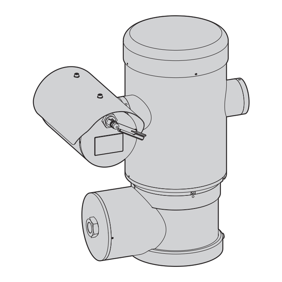
  • Seite 189: Technische Zeichnungen

    14 Technische Zeichnungen Die Maße sind in Millimetern angegeben. Ø 138 N°4 M10 Abb. 57 MAXIMUS MPXHD. MNVCMPXHD_1801_DE...
  • Seite 190: A Anhang - Kennzeichnungsschlüssel

    DE - Deutsch - Bedienungsanleitung A Anhang - Kennzeichnungsschlüssel A.1 Kennzeichnung ATEX 2 G Ex db ÐÐC T6 Gb T -40°C to +60°C ÏÐÐ ÐÐ 2 D Ex tb ÐÐÐC T85°C Db T -40°C to +60°C Ï IP66 Abb. 58 Ï...
  • Seite 191: Kennzeichnung Iecex

    A.2 Kennzeichnung IECEx Ex db eeC T6 Gb T -40°C to +60°C Ex tb eeeC T85°C Db T -40°C to +60°C IP66 Abb. 59 Ex db ÐÐC Tfi -40°C to +60°C Ex-geschütztes Gehäuse für explo- Gas- Gruppe Gastemperaturklassen Gas-Schutzgrad des Geräts Temperaturbereich der Installation sionsgefährdete Bereiche Ex tb...
  • Seite 192: Gasgruppen Klassifizierung

    A.3 Gasgruppen Klassifizierung Die nachstehende Tabelle zeigt die Einteilung einiger Gase und Dämpfe nach Explosionsschutzgruppen und Temperaturen. Ein vollständiges Verzeichnis enthalten IEC/EN60079-12 und IEC/EN60079-20. GASGRUPPEN KLASSIFIZIERUNG Temperaturklassifizierung (Maximale oberflächliche Temperatur des Gehäuses) 1 Gruppe T1 450°C 300°C 200°C 135°C 100°C 85°C Methan Aceton...
  • Seite 193: B Anhang - Flammenverlauf

    B Anhang - Flammenverlauf Die höchstzulässige Spaltweite (ic) ist geringer als wie in Tabelle 3 der EN 60079-1:2014 gefordert wird, siehe untenstehende Angaben: HÖCHSTZULÄSSIGE FLAMMENVERLAUF MINDESTLÄNGE (MM) KOMMENTAR SPALTWEITE (MM) Unter den Bauteilen der Zeichnung 0.249 25.4 Zylindrische Verbin- BRT2MPXALBPAN-EX e BRT2MPXTAPINF-EX dung, von Lagern getragen Unter den Bauteilen der Zeichnung...
  • Seite 194 Email: info@videotec.com Tel. +33 1 60491816 - Fax +33 1 69284736 Email: info.fr@videotec.com Asia Pacific Videotec (HK) Ltd Americas Videotec Security, Inc. Flat 8, 19/F. On Dak Industrial Building, No. 2-6 Wah Sing Street Gateway Industrial Park, 35 Gateway Drive, Suite 100 Kwai Chung, New Territories - Hong Kong Plattsburgh, NY 12901 - U.S.A.
  • Seite 195 РУССКИЙ MAXIMUS MPXHD Взрывобезопасная PTZ-камера с разрешением Full HD Русский - Руководство по эксплуатации...
  • Seite 197 Комплект оборудования Р У С С К И Й 1 О настоящем руководстве ........................7 1.1 Типографские условные обозначения ............................7 2 Примечания в отношении авторского права и информация о торговых марках..... 7 3 Правила техники безопасности ......................7 4 Обозначение ............................9 4.1 Описание...
  • Seite 198 9.1 Интерфейс программного обеспечения .............................25 9.1.1 Минимальные системные требования ................................25 9.1.2 Процедура настройки конфигурации через программное обеспечение ..................25 9.1.3 Установка программного обеспечения ................................26 9.2 Веб-интерфейс ......................................28 9.2.1 Начальная страница ........................................ 28 9.2.2 Страница пользовательских элементов управления..........................28 9.2.3 Страница...
  • Seite 199 14 Технические чертежи ........................43 A Приложение - Коды маркировки ..................... 44 A.1 Маркировка ATEX ....................................44 A.2 Маркировка IECEx ....................................45 A.3 Классификация группы "Газы" .................................46 B Приложение - Пламягасящая дорожка ................... 47 MNVCMPXHD_1801_RU...
  • Seite 200 MNVCMPXHD_1801_RU...
  • Seite 201: Настоящем Руководстве

    1 О настоящем руководстве 3 Правила техники безопасности Внимательно ознакомьтесь со всей документацией, входящей в комплект поставки, перед тем как приступить к установке и эксплуатации данного оборудования. Всегда ПРЕДУПРЕЖДЕНИЕ! Данное устройство должно держите руководство под рукой, чтобы им можно было быть...
  • Seite 202 • Прочитайте данное руководство. • Данное устройство предоставляет возможность дистанционного управления и может менять положение • Сохраните данное руководство. в любой момент. Устройство необходимо устанавливать • Соблюдайте все меры предосторожности. таким образом, чтобы избежать нанесения травм • Выполняйте все указания. движущимися...
  • Seite 203: Обозначение

    Устройства позиционирования для взрывобезопасных устройства позиционирования; его скорость при поворотных камер с увеличительным объективом непрерывном горизонтальном вращении достигает 100°/с, (PTZ-камер) серии MAXIMUS MPXHD разработаны а угол вертикального наклона составляет от -90° до +90°. для обеспечения горизонтального и вертикального PTZ-устройств MAXIMUS MPXHD управляет функциями...
  • Seite 204: Маркировка Изделия

    4.2 Маркировка изделия Рис. 3 Символ CE Сертификат ATEX: Наименование и адрес производителя • Номер сертификата ATEX Идентификационный код модели • Классификация по типу зоны размещения, методу защиты и температурному классу, для которых Температура окружающей среды, соответствующая допускается применение данного устройства идентификационному...
  • Seite 205: Подготовка Устройства К Использованию

    5 Подготовка устройства к Устройство считается выключенным только при использованию отключении источника питания и отсоединении кабелей, ведущих к другим устройствам. Любое изменение, которое выполняется без Выполнить подключения и лабораторные разрешения, явным образом предоставленного испытания, перед установкой на месте производителем, аннулирует гарантии и применения.
  • Seite 206: Комплект Оборудования

    5.3 Комплект оборудования 5.4 Безопасная утилизация упаковочных материалов Проверьте комплект оборудования на соответствие представленному ниже списку материалов: Упаковочные материалы могут подвергаться переработке. • 1 невоспламеняющаяся наводка Технический специалист установщика отвечает за сортировку материалов для переработки, а также за • 1 солнцезащитный козырек соблюдение...
  • Seite 207: Подготовительные Работы Перед Установкой

    5.5 Подготовительные работы перед 5.5.1 Крепление к парапету или на потолок установкой Установите адаптер (01) с нижней стороны устройства с помощью 4 винтов (A4 класс 70) из нержавеющей стали с плоской потайной головкой под торцевой ключ M10x20mm Для установки используйте подходящие (02).
  • Seite 208: Крепление С Помощью Кронштейна

    5.5.2 Крепление с помощью кронштейна 5.5.3 Крепление устройства к адаптеру для установки на стойке или адаптеру для Кронштейн может быть закреплен на вертикальной стене. Используйте винты и приспособления для крепления на установки на угол стене, которые способны выдержать вес, превышающий Перед...
  • Seite 209: Крепление С Помощью Адаптера Для Установки На Угол

    5.5.3.2 Крепление с помощью адаптера для 5.5.4 Установка солнцезащитного козырька установки на угол Перед тем как установить солнцезащитный Закрепите настенный кронштейн на адаптере для козырек (при его наличии), снимите. установки на угол с помощью 4 шайб, 4 пружинных шайб из Закрепите...
  • Seite 210: Монтаж

    соответствует местным нормативным или обратном положении (установка на потолок). При требованиям и спецификациям. установке в настоящей позиции, реконфигурация функций VIDEOTEC настоятельно рекомендует проверить направления и контроля телекамеры, выполняется конфигурацию и эксплуатационные характеристики программой системы. устройства перед его окончательной установкой в...
  • Seite 211: Подключение Кабелей К Основанию

    6.3 Подключение кабелей к В основании устройства размещается отсек подключений для ввода кабелей с резьбовым отверстием 3/4” NPT. основанию Резьбовой наконечник открывает доступ к плате подключения со съемными разъемами, которые позволяют ПРЕДУПРЕЖДЕНИЕ! Система электропитания, установщику подключить кабели. к которой подключается устройство, должна иметь...
  • Seite 212: Описание Платы Разъемов

    6.4 Описание платы разъемов 6.5 Ввод кабелей ОПИСАНИЕ ПЛАТЫ Для нормального функционирования устройства телеметрическая линия не Разъем/Клемма Функция требуется. Линия электропитания Реле, аварийные сигналы Соединения выполняются в соответствии с требованиями Последовательная линия стандарта IEC/EN60079-14 в целях предотвращения распространения пламени или взрывной волны от FUS1 Предохранитель...
  • Seite 213: Подключение Линии Питания

    6.6 Подключение линии питания Все сигнальные кабели необходимо собрать в пучок с помощью кабельной стяжки. В зависимости от модели на устройство может подаваться разное напряжение сети питания. Значение напряжения Размеры силовых кабелей должны соответствовать сети указано на идентификационной этикетке устройства. ( соотношению...
  • Seite 214: Подключение Ethernet-Кабеля

    6.7 Подключение Ethernet-кабеля 6.8 Подключение аварийных сигналов и реле При прокладывании проводов не подключайте кабель RS-485 и видеокабель. Найдите на плате клемму реле и сигналов тревоги и клемму последовательной линии (J3, J9, 6.4 Описание платы Настоятельно рекомендуется использовать Ethernet-кабели разъемов, страница 18). со...
  • Seite 215: Подключение Аварийного Сигнала К Сухому Контакту

    6.8.1 Подключение аварийного сигнала к 6.8.3 Подключение системы омывателя сухому контакту Дополнительная информация по конфигурации В случае передачи сигнала тревоги через сухой контакт и использованию представлена в (сигнал тревоги AL1), выполните подключение, как соответствующем руководстве. показано на рисунке. Когда моющая установка включена, реле используется...
  • Seite 216: Закрытие Отсека Подключений

    установку. Устройство может больше не подходить для безопасной установки в потенциально взрывоопасной среде. В таком случае обратитесь за технической поддержкой VIDEOTEC. Необходимо менять уплотнительное кольцо на новое после каждого открытия. Убедитесь в отсутствии грязи и инородных частиц. Смажьте часть крышки отсека для подключений, которая...
  • Seite 217: Инструкции По Безопасной Эксплуатации

    требованиям действующего местного законодательства. Перед началом установки внимательно ознакомьтесь со Установка устройства должна осуществляться только всеми пунктами настоящего руководства. квалифицированным техническим персоналом. VIDEOTEC настоятельно рекомендует проверить 7.1.3 Правила обеспечения конфигурацию и эксплуатационные характеристики взрывобезопасности устройства перед его окончательной установкой в...
  • Seite 218: Включение

    8 Включение 8.1 Меры, принимаемые до включения питания устройства во Процесс автоматического предварительного взрывоопасной атмосфере подогрева (De-Ice) активируется при каждом включении устройства, если температура Убедитесь в том, что устройство и прочие окружающей среды ниже 0°C. Данный элементы системы снабжены защитными процесс...
  • Seite 219: Конфигурация

    подачу электропитания и запустите браузер (Microsoft Рис. 21 Internet Explorer® 6.0 или более новой версии). Устройство может работать только по протоколу ONVIF или TCAM (VIDEOTEC). При использовании протокола ONVIF убедитесь в том, что в устройстве задано точное время, или выполните настройку конфигурации сервера NTP. (9.2.5 Страница...
  • Seite 220: Установка Программного Обеспечения

    9.1.3 Установка программного обеспечения Задайте имя камеры и устройства. Выберите протокол ONVIF или TCAM и задайте IP-адрес устройства и учетные Вставьте компакт-диск и дождитесь автоматического данные. Выберите профили потоков и убедитесь в том, что запуска программы или откройте установщик. Откроется функция...
  • Seite 221 Чтобы воспроизвести записи с камер на разных После добавления сервер следует зарегистрировать для компьютерах, установите TVMS-клиент и используйте его обеспечения возможности его просмотра. Перетащите для удаленного подключения к TVMS-серверу. Настройте иконку сервера в правую колонку, как показано на рисунке. конфигурацию клиента, осуществив вход с помощью используемых...
  • Seite 222: Веб-Интерфейс

    9.2 Веб-интерфейс 9.2.2 Страница пользовательских элементов управления При первом подключении используйте адрес, Чтобы управлять устройством через браузер, выберите отличный от 192.168.10.100. функцию User Control (Пользовательское управление). Откроется новое окно с виртуальной клавиатурой для Поддерживаемые браузеры: Microsoft Internet ввода команд. Explorer, Microsoft Edge, Google Chrome, Mozilla Firefox.
  • Seite 223: Страница Параметров Устройства

    9.2.3 Страница параметров устройства • Focus Near/Focus Far В строке меню Device Settings можно посмотреть информацию о коде продукта, серийном номере, MAC- адресе, версии прошивки и оборудования. Рис. 33 • Wiper/Washer: После установки и настройки работы резервуара посылается команда для включения стеклоочистителя...
  • Seite 224: Страница Конфигурации Сети

    9.2.5 Страница конфигурации сети NTP-сервер: Можно также указать, требуется ли синхронизировать устройство с внешним NTP-сервером Пункт меню позволяет изменить настройки сети (Сетевым протоколом времени). поворотного продукт. Здесь можно принять решение, • ОТКЛЮЧЕН (DISABLED): Выберите эту опцию, если вы требуется ли устройству статический адрес, динамический не...
  • Seite 225: Страница Параметров Движения

    9.2.7 Страница параметров движения • Ограничения наклона (Tilt Limits): Включает ограничения наклона. Пункт меню Movement Parameters позволяет • Tilt Start: Устанавливает начальную точку наклона. контролировать через интернет все параметры поворотного устройства. • Tilt End: Устанавливает конечную точку наклона. • Offset Pan: Поворотное устройство имеет механически заданное...
  • Seite 226: Страница Патрулирования (Patrol Page)

    9.2.7.2 Страница патрулирования (Patrol Page) • Speed of Movements Default: Скорость, используемая при автоматическом панорамном наблюдении и Пункт меню Patrol позволяет указать предварительно патрулировании. установленные значения для включения и отключения • Impose Default Speed: Используемая по умолчанию патрулирования. Функция патрулирования приводит скорость...
  • Seite 227: Страница Цифрового Входа/Выхода

    9.2.10 Страница цифрового входа/выхода 9.2.13 Страница параметров кодера Пункт меню Digital I/O позволяет выполнять настройку В строке меню «Параметры кодера» можно настроить конфигурации имеющихся цифровых каналов устройства. до 4 видеопотоков устройства. Первый поток сжимается Далее приводится краткое описание настраиваемых обязательно по алгоритму H.264/AVC, в то время как другие параметров...
  • Seite 228: Страница Настроек Камеры

    9.2.14 Страница настроек камеры • Другие опции (Other): Позволяет установить другие значения: Зеркальное отображение (Image Mirror), Встроенную в устройство камеру можно настроить в меню Уменьшение шума (Noise Reduction), Широкий Camera Parameters: динамический диапазон (Wide Dynamic) (Visibility • Расширенный режим: Данный режим позволяет более Enhancer), Высокое...
  • Seite 229: Страница С Описанием Функций Экранного Меню

    9.2.15 Страница с описанием функций экранного меню Start В устройстве можно задать четыре области панорамного наблюдения и выбрать отображение информационного 0° текста на экране в зависимости от положения поворотного устройства. Четыре области могут быть расположены рядом. Для каждой области можно задать следующие параметры: •...
  • Seite 230: Страница Анализа Видеоизображения

    9.2.16 Страница анализа видеоизображения 9.2.18 Factory Default Устройство можно настроить для передачи сигналов Перед тем как приступить к выполнению тревоги по стандарту ONVIF при обнаружении движения. технического обслуживания или ремонта На данной странице можно задать следующие параметры: устройства, убедитесь в отсутствии потенциально...
  • Seite 231: Специальные Элементы Управления

    9.3 Специальные элементы управления СПЕЦИАЛЬНЫЕ ЭЛЕМЕНТЫ УПРАВЛЕНИЯ Действие Элемент управления Протокол TCAM ONVIF (вспомогательная команда) Включение стеклоочистителя Сохранить Preset 85 tt:Wiper|On Отключение стеклоочистителя Сохранить Preset 86 tt:Wiper|Off Washer Сохранить Preset 87 tt:Очистка Процедура|On Ночной Режим On Сохранить Preset 88 tt:ИК-лампа|On Ночной...
  • Seite 232: Техническое Обслуживание

    инструкции по техническому обслуживанию, предоставляемые с каждым комплектом запасных частей. При необходимости проведения технического обслуживания рекомендуется направить изделие в лабораторию, сотрудники которой выполнят все требуемые операции. При обращении за поддержкой в компанию VIDEOTEC предоставьте серийный номер и идентификационный код устройства. MNVCMPXHD_1801_RU...
  • Seite 233: Информация Об Утилизации И Переработке

    неисправностей Ремонт этого устройства может выполняться только прошедшими надлежащее обучение сотрудниками или под наблюдением сотрудников компании VIDEOTEC в соответствии с существующими условиями: IEC/EN60079-19. В том случае, если перечисленные ниже проблемы не удается устранить или если вы столкнулись с другими проблемами, описание...
  • Seite 234: Технические Характеристики

    13 Технические характеристики 13.4 Сеть Ethernet подключение: 10BASE-T/100BASE-T 13.1 Общие сведения Разъем: RJ45 Конструкция из нержавеющей стали марки AISI 316L Длина кабеля: 100m max Пассивированные и электрополированные наружные 13.5 Видео поверхности Система управления динамическим позиционированием Видеокодер 13.2 Механические характеристики • Протокол связи: ONVIF, Profile S •...
  • Seite 235: Камеры

    13.7 Камеры Система фокусировки: Auto (Чувствительность (Sensitivity): Норма (Normal), Низкий (Low)), Автоматическая Day/Night Full HD 30x фокусировка одним нажатием кнопки (One-push AF), Ручной, Компенсация фокуса с использованием ICR, Разрешение: Full HD 1080p (1920x1080pixel) Интервал автоматической фокусировки (Interval AF), Датчик изображения: 1/2.8 type Exmor™ CMOS sensor Триггер...
  • Seite 236: Расчетные Электрические Характеристики

    13.10 Расчетные электрические характеристики РАСЧЕТНЫЕ ЭЛЕКТРИЧЕСКИЕ ХАРАКТЕРИСТИКИ Напряжение Стандартные условия эксплуатации, которые Краткосрочный предварительный нагрев против сети питания должны быть указаны на табличке с маркировкой обледенения. Максимальное потребление для поддержания минимальной внутренней температуры 5°C 230Vac 0.11A, 50/60Hz, 25.3W 0.52A, 50/60Hz, 120W 24Vac 1.08A, 50/60Hz, 25.9W 5A, 50/60Hz, 120W...
  • Seite 237: Технические Чертежи

    14 Технические чертежи Размеры указаны в миллиметрах. Ø 138 N°4 M10 Рис. 57 MAXIMUS MPXHD. MNVCMPXHD_1801_RU...
  • Seite 238: A Приложение - Коды Маркировки

    RU - Русский - Руководство по эксплуатации A Приложение - Коды маркировки A.1 Маркировка ATEX 2 G Ex db ÐÐC T6 Gb T -40°C to +60°C ÏÐÐ ÐÐ 2 D Ex tb ÐÐÐC T85°C Db T -40°C to +60°C Ï IP66 Рис.
  • Seite 239: Маркировка Iecex

    A.2 Маркировка IECEx Ex db eeC T6 Gb T -40°C to +60°C Ex tb eeeC T85°C Db T -40°C to +60°C IP66 Рис. 59 Ex db ÐÐC Tfi -40°C to +60°C Взрывобезопасный корпус для Группа "Газы" Классификация температуры газа Уровень защиты газовых Диапазон...
  • Seite 240: Классификация Группы "Газы

    A.3 Классификация группы "Газы" Приведенная далее таблица показывает классификацию некоторых газов и паров, в соответствии с группами взрывобезопасности и температурами. Полный перечень следует смотреть в стандарте IEC/EN60079-12 и в IEC/EN60079-20. КЛАССИФИКАЦИЯ ГРУППЫ "ГАЗЫ" Температурный класс (Максимальная поверхностная температура кожуха) 1 Класс...
  • Seite 241: B Приложение - Пламягасящая Дорожка

    B Приложение - Пламягасящая дорожка Максимальный конструктивный зазор (ic) меньше, чем требуется согласно Таблице 3 стандарта EN 60079-1:2014, как указано ниже: МАКСИМАЛЬНЫЙ МИНИМАЛЬНАЯ ПЛАМЯГАСЯЩАЯ ДОРОЖКА КОММЕНТАРИЙ ЗАЗОР (ММ) ДЛИНА (ММ) Между компонентами чертежа 0.249 25.4 Цилиндрическое BRT2MPXALBPAN-EX e BRT2MPXTAPINF-EX соединение, опирающееся...
  • Seite 242 Email: info@videotec.com Tel. +33 1 60491816 - Fax +33 1 69284736 Email: info.fr@videotec.com Asia Pacific Videotec (HK) Ltd Americas Videotec Security, Inc. Flat 8, 19/F. On Dak Industrial Building, No. 2-6 Wah Sing Street Gateway Industrial Park, 35 Gateway Drive, Suite 100 Kwai Chung, New Territories - Hong Kong Plattsburgh, NY 12901 - U.S.A.
  • Seite 243 PORTUGUÊS MAXIMUS MPXHD Câmera PTZ Full HD à prova de explosão Português - Manual de instruções...
  • Seite 245 Sumário P O R T U G U Ê S 1 Informações neste manual.................... 7 1.1 Convenções tipográficas ............................7 2 Direitos autorais e informações sobre marcas registradas ........7 3 Normas de segurança ....................7 4 Identificação ........................9 4.1 Descrição e designação do produto .........................
  • Seite 246 9.1 Interface de software ............................25 9.1.1 Requisitos mínimos do PC ..............................25 9.1.2 Procedimento de configuração via software.......................25 9.1.3 Instalação do software .................................26 9.2 Interface web ................................28 9.2.1 Página Home ...................................28 9.2.2 Página Controlos de Utilizador ............................28 9.2.3 Página Parâmetros Dispositivo ............................29 9.2.4 Página Estatísticas Dispositivo ............................29 9.2.5 Página Configuração Rede ..............................30 9.2.6 Página Configuração Utilizadores ...........................30...
  • Seite 247 14 Desenhos técnicos ..................... 43 A Apêndice - Codificação da marcação ................. 44 A.1 Marcação ATEX ...............................44 A.2 Marcação IECEx ..............................45 A.3 Classificação dos Grupos de Gás........................46 B Apêndice - Percurso de chama ................... 47 MNVCMPXHD_1801_PT...
  • Seite 248 MNVCMPXHD_1801_PT...
  • Seite 249: Informações Neste Manual

    1 Informações neste manual 3 Normas de segurança Antes de instalar e utilziar esta unidade, deve ser lida ATENÇÃO! O aparelho deve ser ligado com atenção toda a documentação fornecida. Manter a um condutor de terra (ligação à terra o manual ao alcance da mão para consultas futuras. de proteção).
  • Seite 250 • Ler as instruções. • O aparelho é controlado à distância portanto, é possível mudar de posição a qualquer momento. • Conservar as instruções. Instalar o aparelho para evitar acidentes causados • Preste atenção a todos os avisos. pelo contato com partes em movimento, fazendo •...
  • Seite 251: Identificação

    -90 ° e 90 °. plano horizontal e vertical de um invólucro contendo MAXIMUS MPXHD PTZ opera as funções do preset, câmara operando em ambientes industriais nos quais patrulha e auto-pan com uma precisão de 0,02 °.
  • Seite 252: Etiqueta Do Produto

    4.2 Etiqueta do produto Fig. 3 Símbolo CE 10. Certificado ATEX: Nome e endereço do fabricante • Número de certificado ATEX Código de identificação do modelo • Classificação do tipo de área, tipo de proteção, classe de temperatura para os quais é admitida Temperatura ambiente de utilização refere-se ao a utilização deste produto segundo a diretiva código de identificação do modelo...
  • Seite 253: Preparação Do Produto Para O Uso

    5 Preparação do produto O aparelho estará desativado apenas para o uso quando a alimentação não estiver inserida e os cabos de ligação com outros dispositivos forem retirados. Quaisquer modificações não expressamente aprovadas pelo fabricante Realizar conexões e testes de laboratório anulam a garantia e a certificação.
  • Seite 254: Eliminação Segura Dos Materiais De Embalagem

    5.3 Conteúdo 5.4 Eliminação segura dos materiais de embalagem Controlar se o conteúdo corresponde à lista do material abaixo indicada: Os materiais de embalagem são constituídos • 1 PTZ antiexplosão inteiramente por material reciclável. O técnico que fizer a instalação deve eliminá-los segundo as regras •...
  • Seite 255: Os Trabalhos Preparatórios Antes Da Instalação

    5.5 Os trabalhos preparatórios 5.5.1 Fixação ao parapeito ou ao teto antes da instalação Ligar o adaptador (01) ao fundo da unidade utilizando 4 parafusos chanfrados de cabeça plana (02) com sextavado M10x20 mm em aço inox (A4 Executar a instalação utilizando os classe 70).
  • Seite 256: Fixação Com Estribo

    5.5.2 Fixação com estribo 5.5.3 Fixação com cinto de poste ou módulo adaptador angular O suporte pode ser fixado diretamente em um muro vertical. Usar parafusos e elementos de fixação à Para instalar o produto na para a haste ou com um parede, que pode suportar um peso de, pelo menos, ângulo, antes de mais nada, fixar a unidade o suporte 4 vezes maior do que da unidade.
  • Seite 257: Fixação Com Módulo Angular

    5.5.3.2 Fixação com módulo angular 5.5.4 Fixação da cobertura Para garantir o suporte à parede para o módulo Antes de fixar o teto da caixa remover a adaptador de canto, usar 4 arruelas planas, 4 película protetora. arruelas de pressão e 4 parafusos sextavados de aço inoxidável (A4 classe 70) a partir M10x30 mm.
  • Seite 258: Instalação

    A unidade só pode ser instalada na posição normal conformidade com as normas locais. ou invertida (montagem no teto). Se instalada na VIDEOTEC recomenda testar a configuração e o última posição, a reconfiguração das funções de desempenho do equipamento antes de colocar na orientação e controle da câmara são feitos através do...
  • Seite 259: Ligação Dos Cabos À Base

    6.3 Ligação dos cabos à base Na base da unidade existe um compartimento de ligação com o furo roscado, de 3/4 "NPT para a entrada do cabo. ATENÇÃO! O sistema elétrico ao qual está ligada a unidade deve ter um interruptor de Desenroscando a tampa roscada aceder a uma proteção bipolar automática de 15A max.
  • Seite 260: Descrição Da Placa De Conectores

    6.4 Descrição da placa de 6.5 Entrada cabos conectores A linha de telemetria não é necessária para o funcionamento normal do dispositivo. DESCRIÇÃO DA PLACA Conector/Borne Função Para impedir a propagação de chamas ou de explosão a partir do dispositivo para o sistema de Linha de Alimentação cabo ou conduta, e desta última para o ambiente Relé, alarmes...
  • Seite 261: Ligação Da Linha De Alimentação

    6.6 Ligação da linha de Todos os cabos de sinal devem ser alimentação agrupados com uma faixa. De acordo com a versão, podem ser fornecidas Os cabos de alimentação devem ser dimensionados tensões diferentes de alimentação do dispositivo. com base na relação entre a corrente de alimentação O valor de tensão de alimentação está...
  • Seite 262: Ligação Do Cabo Da Rede Ethernet

    6.7 Ligação do cabo da rede 6.8 Ligação ao alarme e relé Ethernet Identificar na placa o borne dos relês e alarmes e o borne da linha serial (J3, J9, 6.4 Descrição da placa de Durante a fiação não conectar o cabo RS- conectores, página 18).
  • Seite 263: Ligação Alarme Com Contato Limpo

    6.8.1 Ligação alarme com contato limpo 6.8.3 Conexão da instalação de lavagem No caso de alarme em contato limpo (alarme AL1), Para obter maiores detalhes sobre como efetuar a ligação conforme ilustrado na figura. configurar e utilizar alarmes, consultar o manual do equipamento relacionado.
  • Seite 264: Fechamento Do Compartimento De Conexões

    Neste caso, entrar em contato com o serviço técnico de VIDEOTEC. A cada abertura o O-ring deve ser substituído por um novo. Verificar se há sujeira ou detritos.
  • Seite 265: Instruções De Funcionamento Em Segurança

    Ler cuidadosamente e completamente este manual A instalação deve ser realizada por pessoal antes de efetuar a instalação. qualificado. VIDEOTEC recomenda testar a configuração e o 7.1.3 Requisitos para a prevenção de desempenho do equipamento antes de colocar explosões na área de instalação final. Utilizar as ferramentas adequadas.
  • Seite 266: Acendimento

    8 Acendimento 8.1 Antes de alimentar a unidade em uma atmosfera O procedimento de preaquecimento potencialmente explosiva automático (De-Ice) pode ser ativado sempre que o dispositivo estiver ligado Garantir que a unidade e os outros em temperatura ambiente inferior a componentes do sistema estejam fechados 0°C.
  • Seite 267: Configuração

    Microsoft Internet Explorer® 6.0 ou superior. Fig. 21 O produto poderá funcionar através do protocolo ONVIF ou TCAM (VIDEOTEC). Se utiliza o protocolo ONVIF, certifique-se de definir a hora correctamente no dispositivo ou de configurar um servidor NTP (9.2.5 Página Configuração Rede, página 30).
  • Seite 268: Instalação Do Software

    9.1.3 Instalação do software Atribua um nome à câmara e ao grupo. Seleccione o protocolo ONVIF ou TCAM e defina o endereço IP do Insira o CD e execute o autoplay ou o instalador. dispositivo e as credenciais de acesso. Seleccione os Isto irá...
  • Seite 269 Para visualizar as câmaras em vários computadores Depois de adicionar o servidor será necessário deve instalar o cliente TVMS e usá-lo para se ligar registá-lo para visualização. Arraste o ícone do remotamente ao servidor TVMS. Para configurar o servidor na coluna da direita, como indicado na cliente, aceda com as credenciais por defeito.
  • Seite 270: Interface Web

    9.2 Interface web 9.2.2 Página Controlos de Utilizador Para controlar o dispositivo via navegador, seleccione Na primeira ligação atribua um endereço o item Controlos do Utilizador. Isto irá abrir uma diferente 192.168.10.100. nova janela com um teclado virtual para enviar os comandos.
  • Seite 271: Página Parâmetros Dispositivo

    9.2.3 Página Parâmetros Dispositivo • Focus Near/Focus Far No item do menu Parâmetros do Dispositivo, é possível visualizar as informações sobre o código do produto, o número de série, o endereço MAC, a versão do firmware e a revisão do hardware. Fig.
  • Seite 272: Página Configuração Rede

    9.2.5 Página Configuração Rede NTP Server: Pode também especificar se o dispositivo deve sincronizar com um servidor NTP No item do menu, é possível mudar as configurações (Network Time Protocol) externo. de rede do produto. É possível decidir se o dispositivo •...
  • Seite 273: Página Parâmetros Movimento

    9.2.7 Página Parâmetros Movimento • Limites Tilt: Ativar os limites do Tilt. • Tilt Start: Configurar o limite inicial do Tilt. No item de menu Movement Parameters é possível controlar através da web todos os parâmetros do • Tilt End: Configurar o limite final do Tilt. motor PTZ.
  • Seite 274: Página Patrol

    9.2.7.2 Página Patrol • Speed of Movements Default: A velocidade utilizada nas operações de autopan e patrol. No item de menu Patrol é possível especificar a • Impose Default Speed: A velocidade padrão será predefinição do início e término do patrol. Patrulha é definida como a velocidade de digitalização para uma função que faz a unidade se mover entre dois ou todas as predefinições.
  • Seite 275: Página I/O Digitais

    9.2.10 Página I/O Digitais 9.2.13 Página Parâmetros do Codificador No item do menu Digital I/O é possível configurar os canais digitais presentes no dispositivo. Segue-se No item do menu Parâmetros do Codificador breve descrição dos parâmetros configuráveis para é possível configurar até 4 fluxos de vídeo do cada entrada digital.
  • Seite 276: Página Parâmetros Câmara

    9.2.14 Página Parâmetros Câmara • Outro: Permite configurar outros valores: Imagem Especular, Redução De Ruído, Wide Dynamic No item do menu Camera Parameters é possível (Visibility Enhancer), Alta Resolução, Controle da configurar a câmera de vídeo incorporada no Abertura, Defog, Correção de Sobre-exposição. dispositivo: •...
  • Seite 277: Página Osd Direcional

    9.2.15 Página OSD Direcional O dispositivo suporta a definição de quatro regiões Start pan e a visualização em vídeo de texto informativo com base na posição do panoramizador. As quatro 0° áreas podem ser sobrepostas. É possível definir os seguintes parâmetros para cada área: •...
  • Seite 278: Página Análise Do Vídeo

    9.2.16 Página análise do vídeo 9.2.18 Factory Default O dispositivo pode ser configurado para que emita Antes de realizar intervenções técnica no alarmes de detecção de movimento por eventos aparelho, certificar-se de que não haja ONVIF. atmosfera potencialmente explosiva. Nesta página é possível definir os parâmetros a seguir: Se a senha de acesso não está...
  • Seite 279: Comandos Especiais

    9.3 Comandos especiais COMANDOS ESPECIAIS Ação Comando Protocolo TCAM ONVIF (auxiliary command) Wiper Start Salvar Preset 85 tt:Wiper|On Wiper Stop Salvar Preset 86 tt:Wiper|Off Washer Salvar Preset 87 tt:Washing Procedure|On Modalidade Noturna On Salvar Preset 88 tt:IRLamp|On Modalidade Noturna Off Salvar Preset 89 tt:IRLamp|Off Reboot dispositivo...
  • Seite 280: Manutenção

    É aconselhável, em todos os eventos de manutenção, reconduzir o produto ao laboratório para realizar as operações necessárias. Quando for contactado o serviço técnico de VIDEOTEC é necessário fornecer o número de série juntamente com um código de identificação do aparelho. MNVCMPXHD_1801_PT...
  • Seite 281: Informações Sobre Descarte E Reciclagem

    12 Solução de problemas A reparação deste produto deve ser efetuada por pessoal treinado adequadamente ou com a supervisão do pessoal VIDEOTEC em conformidade com as normas previstas: IEC/EN60079-19. Para qualquer problemática não descrita ou se os problemas indicados a seguir porventura persistirem, entrar em contato com o centro de assistência autorizado.
  • Seite 282: Dados Técnicos

    13 Dados técnicos 13.4 Rede Conexão Ethernet: 10BASE-T/100BASE-T 13.1 Geral Conector: RJ45 Fabricada em aço inox AISI 316L Comprimento do cabo: 100m max Superfícies externas passivadas e eletropolidas 13.5 Vídeo Sistema dinâmico de controle da posição Codificador de vídeo 13.2 Mecânica •...
  • Seite 283: Câmaras

    13.7 Câmaras Sistema Foco: Auto (Sensibilidade: Normal, Baixa), AF simples, Manual, Foco de compensação em ICR On, Day/Night Full HD 30x Intervalo AF, Zoom trigger AF Resolução: Full HD 1080p (1920x1080pixel) Efeitos imagem: E-flip, Imagem espelhada, Melhoramento da cor Sensor de imagem: 1/2.8 type Exmor™ CMOS sensor Controle da Exposição: Auto, EV Compensation, Pixels Efetivos: aprox.
  • Seite 284: Consumo Elétrico

    13.10 Consumo elétrico CONSUMO ELÉTRICO Fonte de alimen- O uso normal e específico na placa de marcação Consumo máximo durante o processo de preaqueci- tação mento automático (Descongelamento) para manter uma temperatura interna mínima de 5 ° C 230Vac 0.11A, 50/60Hz, 25.3W 0.52A, 50/60Hz, 120W 24Vac 1.08A, 50/60Hz, 25.9W...
  • Seite 285: Desenhos Técnicos

    14 Desenhos técnicos As medidas indicadas estão expressas em milímetros. Ø 138 N°4 M10 Fig. 57 MAXIMUS MPXHD. MNVCMPXHD_1801_PT...
  • Seite 286: A Apêndice - Codificação Da Marcação

    PT - Português - Manual de instruções A Apêndice - Codificação da marcação A.1 Marcação ATEX 2 G Ex db ÐÐC T6 Gb T -40°C to +60°C ÏÐÐ ÐÐ 2 D Ex tb ÐÐÐC T85°C Db T -40°C to +60°C Ï...
  • Seite 287: Marcação Iecex

    A.2 Marcação IECEx Ex db eeC T6 Gb T -40°C to +60°C Ex tb eeeC T85°C Db T -40°C to +60°C IP66 Fig. 59 Ex db ÐÐC Tfi -40°C to +60°C Caixa antiexplosão para ambientes Grupo gás Classificação da temperatura Nível de proteção do equipamento Alcance de temperatura da instalação potencialmente explosivos...
  • Seite 288: Classificação Dos Grupos De Gás

    A.3 Classificação dos Grupos de Gás A tabela abaixo apresenta a classificação de certos gases e vapores de acordo com os grupos de proteção e da temperatura. Para uma lista completa consulte a IEC/EN60079-12 e IEC/EN60079-20. CLASSIFICAÇÃO DOS GRUPOS DE GÁS Classe de temperatura (Máxima temperatura superficial °C do invólucro) 1 Classe 450°C...
  • Seite 289: B Apêndice - Percurso De Chama

    B Apêndice - Percurso de chama A lacuna construtiva máxima (ic) é menor do que o valor requerido pela Tabela 3 da EN 60079-1:2014, como indicado abaixo: COMPRIMENTO PERCURSO DE CHAMA LACUNA MÁXIMA (MM) COMENTÁRIO MÍNIMO (MM) Entre componentes do desenho 0.249 25.4 Junta cilíndrica susten-...
  • Seite 290 Email: info@videotec.com Tel. +33 1 60491816 - Fax +33 1 69284736 Email: info.fr@videotec.com Asia Pacific Videotec (HK) Ltd Americas Videotec Security, Inc. Flat 8, 19/F. On Dak Industrial Building, No. 2-6 Wah Sing Street Gateway Industrial Park, 35 Gateway Drive, Suite 100 Kwai Chung, New Territories - Hong Kong Plattsburgh, NY 12901 - U.S.A.
  • Seite 291 한국어 MAXIMUS MPXHD 방폭형 Full HD PTZ 카메라 한국어 - 지침 설명서...
  • Seite 293 요약 한 국 어 1 설명서에 있는 정보들 .................. 7 1.1 인쇄합의..........................7 2 저작권 및 상표에 대한 정보들 주의사항 ............7 3 안전규칙 ....................7 4 식별 ....................... 9 4.1 설명과 제품의 명시 ....................... 9 4.2 제품의 검인 ........................10 5 사전에...
  • Seite 294 9.1 인터페이스 소프트웨어 ....................... 25 9.1.1 PC의 최소 요구들 ........................... 25 9.1.2 소프트웨어를 통해 형성을 진행합니다.................... 25 9.1.3 소프트웨어 설치 ..........................26 9.2 인터페이스 웹 ........................28 9.2.1 Home 화면 ............................ 28 9.2.2 사용자 검점들 화면 ........................28 9.2.3 장치 파라미터 화면 ........................29 9.2.4 통계...
  • Seite 295 14 기술 도면 .................... 43 A 부록 - 마킹 코드 ..................44 A.1 ATEX 마킹 .......................... 44 A.2 IECEx 마킹 ......................... 45 A.3 가스 그룹 분류 ........................46 B 부록 - 화염경로 ..................47 MNVCMPXHD_1801_KO...
  • Seite 296 MNVCMPXHD_1801_KO...
  • Seite 297: 설명서에 있는 정보들

    1 설명서에 있는 정보들 3 안전규칙 장치를 설치 및 사용하기 전에 제공된 모든 문서를 주의! 장치는 접지 도체에 연결되어야 합니다 주의 깊게 읽어 보십시오. 나중에 참조할 수 있도록 (보호용 접지). 이 연결은 전력선 커넥터를 편리한 장소에 설명서를 보관하십시오. 통해서만 수행해야 함 (J1, 6.4 컨넥터 1.1 인쇄합의...
  • Seite 298 • 해당 지시사항을 읽으십시오. • 이 장치는 원격으로 제어되며 언제라도 위치를 바꿀 수 있습니다. 움직이는 부품에 의해 다치는 사람이 • 해당 지시사항을 지키십시오. 없도록 설치되어야 합니다. 움직이는 부품이 다른 • 모든 경고사항에 주의하십시오. 물체를 치거나 위험한 상황을 생성하지 않도록 • 모든 지시사항을 따르십시오. 설치되어야...
  • Seite 299: 설명과 제품의 명시

    4 식별 MAXIMUS MPXHD PTZ는 연속, 고속 회전, 위치 조절 정확성 및 우수한 영상 품질, 최상의 견고성 및 간단한 4.1 설명과 제품의 명시 시스템 구성을 제공합니다. 속도와 정확도는 주요한 팬/틸트 특성으로, 연속 수평 MAXIMUS MPXHD 시리즈 폭발 방지 팬-틸트-줌(PTZ) 회전은 100°/s, 수직 범위는 -90° ~ +90°에 달합니다.
  • Seite 300: 제품의 검인

    4.2 제품의 검인 그림. 3 CE 심볼 10. ATEX 인증: 제조업체의 이름 및 주소 • ATEX 인증 번호 모델 식별 코드 • 이 제품이 ATEX 지령에 부합하여 사용될 수 있는 존 유형에 대한 분류, 보호 방법, 온도 등급 모델 식별 번호를 참조한 사용 주변 온도 11.
  • Seite 301: 사전에 대한 제품 준비

    5 사전에 대한 제품 준비 전원 공급장치가 분리되고 다른 장치에 대한 연결 케이블이 제거된 경우에만 장치의 제조업체에 의해 명시적으로 승인되지 않은 스위치를 끄는 것을 고려할 수 있습니다. 변경은 보증과 인증 모두를 무효로 합니다. 연결 후 현장에서 설치하기 전에 실험실에서 5.1 사용 전에 안전 예방조치 시험하십시오.
  • Seite 302: 포장 재료의 안전한 폐기

    5.3 내용물 5.4 포장 재료의 안전한 폐기 아래 목록 재료의 표와 내용물이 일치하는지 포장의 재료들은 재활용 재료에 의해서 온전히 점검합니다: 만들어졌습니다. 분리수거의 방법이나 사용 국가의 현 규범에 따라서 폐기처분하는 기술 설치자의 • 1 폭발 방지 P&T 관리입니다. • 1 햇빛 차단 •...
  • Seite 303: 설치 전에 준비 작업

    5.5 설치 전에 준비 작업 5.5.1 난간 또는 천장 장착 고정 4개의 스테인리스 스틸(A4 클래스 70) 소켓 플랫 헤드 설치용으로 알맞은 도구를 사용하십시오. 장치 캡 나사 M10 x 20mm (02)를 사용하여 어댑터(01)를 설치 현장의 특성에 따라 특정 도구가 설치를 장치의 바닥에 부착합니다. 위해...
  • Seite 304: 브래킷으로 고정하기

    5.5.2 브래킷으로 고정하기 5.5.3 장치를 전봇대 장착 어댑터나 코너 장착 어댑터에 고정 브래킷은 수직 벽면에 고정될 수 있습니다. 적어도 장치의 무게보다 4배를 견딜 수 있는 나사와 벽면 고정 제품을 기둥이나 벽 모서리에 설치하려면 먼저 장치를 사용하십시오. 장치를 벽 브래킷에 고정하십시오. (5.5.2 브래킷으로 고정하기, 페이지...
  • Seite 305: 코너 어댑터로 고정하기

    5.5.4 햇빛 차단기 고정하기 5.5.3.2 코너 어댑터로 고정하기 4개의 와셔, 4개의 스테인리스 스틸 그로워 와셔와 햇빛 가리개를 설치하기 전에 보호 필름을 4개의 육각 스테인리스 스틸 볼트(A4 등급 70) 제거하십시오. M10x20mm을 사용하여 벽면용 브래킷을 코너 장착 어댑터에 고정합니다. 제공된 나사와 와셔를 사용하여 하우징에 선실드를 고정합니다.
  • Seite 306: 사용 범위

    설치가 현지 규정과 사양에 부합하는지 확인합니다. 이 시스템은 표준 또는 반대 위치(천장 장착)에만 VIDEOTEC은 장치를 최종 설치 장소에 설치하기 전에 설치할 수 있습니다. 반대 작동을 위한 설치 시, 일반 및 성능을 시험해 볼 것을 강력히 권장합니다 (6.3 작동의 경우 시스템 소프트웨어를 통해 카메라 방향 및...
  • Seite 307: 베이스에 케이블 연결

    6.3 베이스에 케이블 연결 3/4” NPT의 나사줄이 있는 구멍을 가진 케이블 삽입용 접속함은 장치의 받침에 위치해 있습니다. 주의! 장치가 연결된 전기 설비는 최대 나사줄이 있는 뚜껑은 설치자가 케이블을 연결하는데 15A에 의한 자동 양극성의 보호 스위치가 도움을 주는 제거 가능한 커넥터들이 있는 연결 보드에 구비되어져야...
  • Seite 308: 컨넥터 색인카드의 기술

    6.4 컨넥터 색인카드의 기술 6.5 케이블 인입구 원격 측정 선은 장치의 일반 기능으로 꼭 필요한 카드의 설명 것은 아닙니다. 커넥터/단자 기능 전력 공급선 장치에서 도관 시스템 또는 케이블 그랜드에서 외부 릴레이, 알람 환경으로 화염이나 폭발이 확산되지 않도록 IEC/ EN60079-14를 준수하는 연결을 사용하십시오. 직렬...
  • Seite 309: 전원공급 라인 연결

    6.6 전원공급 라인 연결 모든 시그널 케이블들은 밴드로 그룹져져야 합니다.. 버전에 따라서 장치에 다른 전원공급 전압이 제공되어 질 수 있습니다. 전원 공급 장치의 전압은 제품 식별 전원 케이블의 크기는 공급 전류와 커버할 거리 사이의 라벨에 표시되어 있습니다. (4.2 제품의 검인, 페이지 비율에...
  • Seite 310: 이더넷 네트워크 케이블 연결

    6.7 이더넷 네트워크 케이블 연결 6.8 알람 및 릴레이 연결 릴레이 및 알람 단자와 보드의 직렬선 단자 식별 (J3, 배선하는 동안 RS-485 케이블과 비디오 J9, 6.4 컨넥터 색인카드의 기술, 페이지 18). 케이블을 연결하지 마십시오. 연결하려면 차폐 케이블을 사용하십시오. 다음 특성을 가진 이더넷 케이블의 사용을 적극 팬틸트...
  • Seite 311: 무전압 알람 연결

    6.8.1 무전압 알람 연결 6.8.3 세척 시스템 연결 무전압 알람의 경우 (알람 AL1), 그림과 같이 연결을 형성과 경보의 사용에 대한 상세한 내용에 수행하십시오. 대해서는 관련된 악세서리 설명서를 참조합니다. 세척의 설비가 작동되어 질 때 독점적으로 펌프의 작동을 위해 릴레이 이 사용되어집니다 ( 9.2.12 Washer 화면, 페이지...
  • Seite 312: 접속함 닫기

    나사줄 손상이 의심되면, 설치를 보류합니다. 있는 뚜껑과 접속함 사이에 틈이 없는지 확인합니다. 해당 장치는 잠재적 폭발성 분위기에서 더 이상 설치에 안전하지 않을 수 있습니다. 이 경우, VIDEOTEC 기술 지원에 연락하십시오. O-링은 개봉 후마다 새로운 부품으로 교체해야 합니다. 뚜껑에 오물이나 부스러기가 없는지 확인합니다.
  • Seite 313: 안전 운용을 위한 지시사항

    설치를 시작하기에 앞서 본 사용자 핸드북의 전체 확인합니다. 내용을 매우 주의깊게 읽어 주십시오. 전기 장비의 설치는 시행 중인 현지 법률을 준수해야 VIDEOTEC은 장치를 최종 설치 장소에 설치하기 전에 합니다. 및 성능을 시험해 볼 것을 강력히 권장합니다. 적합한 장치는 자격을 갖춘 기술자에 의해서만 배타적으로...
  • Seite 314: 폭발성 대기에 제품을 공급하기 전에

    8 켜짐 8.1 폭발성 대기에 제품을 공급하기 전에 자동예열의 절차(De-Ice)는 0°C 이하의 환경 온도에서 장치가 켜지는 모든 순간을 활성화 할 장치와 다른 설비 구성요소들이 전압 하에 수 있습니다. 이 절차는 저온에서 장치의 올바른 요소들과의 접촉을 방지하기에 적합한 방법으로 작동을 보장하기 위해 필요합니다. 기간은 환경 잘...
  • Seite 315: 인터페이스 소프트웨어

    Microsoft Internet Explorer® 6.0 나 그 이상의 브라우저를 시작합니다. 그림. 21 전동회전대는 프로토콜 ONVIF 또는 TCAM (VIDEOTEC). 을 통해서 작동할 수 있습니다. 프로토콜 ONVIF 사용한다면, 올바르게 장치에 시간을 설정이나 NTP 서버 형성을 확인합니다. (9.2.5 네트워크 형성 화면, 페이지 30). MNVCMPXHD_1801_KO...
  • Seite 316: 소프트웨어 설치

    9.1.3 소프트웨어 설치 이름을 텔레카메라와 그룹에 지정합니다. 프로토콜 ONVIF 혹은 TCAM 선택하고 장치의 IP 주소를 CD를 삽입하고 오토플레이를 시작하거나 설정하고 접근의 신분증명을 설정합니다. 스트리밍의 설치프로그램을 실행합니다. TVMS서버 프로파일를 선택하고 PTZ 사용 사용 항목이 어플리케이션의 설치를 허용하는 웹페이지가 열릴 작동되는지 확인합니다. Ok클릭합니다. 것입니다.
  • Seite 317 여러 컴퓨터의 텔레카메라들을 시각화하기 위해서는 서버를 추가한 후에, 시각화하기 위해서 서버를 TVMS 클리언트를 설치할 필요가 있고 TVMS 서버에 등록해야 합니다. 그림에서 보여지는 것처럼 오른쪽 원격조정을 연결하기 위해서 사용합니다. 클리언트를 열에 서버의 아이콘을 드래그합니다. 형성하기 위해서는 기본 자격증명으로 접근합니다. Login: admin Password: 1234 Setup 버튼을...
  • Seite 318: 인터페이스 웹

    9.2 인터페이스 웹 9.2.2 사용자 검점들 화면 브라우저로 장치 점검하기위해서 사용자 제어 항목을 처음 연결할 때 192.168.10.100 과 다른 선택합니다. 명령들을 보내기 위해서 가상 키보드를 주소를 지정합니다. 가진 새로운 창이 열릴 것입니다. 지원 브라우저: Microsoft Internet Explorer, Microsoft Edge, Google Chrome, Mozilla Firefox.
  • Seite 319: 장치 파라미터 화면

    9.2.3 장치 파라미터 화면 • Focus Near/Focus Far 장치 설정 메뉴에서 제품 코드, 일련번호, MAC 주소, 펌웨어 버전 및 하드웨어 검토에 대한 정보를 볼 수 있습니다. 그림. 33 • Wiper/Washer: 탱크가 설치 및 구성된 경우 명령을 통해 와이퍼와 세척 절차를 활성화합니다. 그림.
  • Seite 320: 네트워크 형성 화면

    9.2.5 네트워크 형성 화면 NTP Server: 또한 장치가 외부 서버 NTP (Network Time Protocol)과 동기화해야 할지도 명시할 수 형성 메뉴의 항목에서 생성물 망의 설정을 변경할 수 있습니다. 있습니다. 장치에 정적으로 할당된 주소가 필요한지 • DISABLED: 장치의 날짜와 시간을 동기화하고 아니면 DHCP를 사용하여 동적으로 할당되거나 싶지...
  • Seite 321: 이동 파라미터 화면

    9.2.7 이동 파라미터 화면 • 틸트 제한: 틸트의 제한들이 활성화됩니다. • Tilt Start: 틸트의 시작의 제한을 설정합니다. 이동 파라미터 메뉴의 항목에서 전동회전대의 모든 파라미터를 웹으로 조절할 수있습니다. • Tilt End: 틸트의 마지막 제한을 설정합니다. • Offset Pan: 전동회전대는 기계적으로 정의된 0° 의...
  • Seite 322: Patrol 화면

    9.2.7.2 Patrol 화면 • Speed of Movements Default: 오토팬과 패트롤의 작업들에서 사용된 속도 패트롤 섹션 하에서 패트롤의 시작과 끝에 대한 • Impose Default Speed: 기본설정의 속도는 모든 사전설정을 명시할 수 있습니다. 패트롤은 두 개 사전설정들에 대한 스캔의 속도처럼 설정되어질 이상의 사전 설정 간에 장치를 이동하는 기능입니다. 것입니다.
  • Seite 323: 디지털 I/O 화면

    9.2.10 디지털 I/O 화면 9.2.13 인코더 파라미터 화면 메뉴 입력 디지털 I/O에서 장치로 이용 가능한 디지털 인코더 설정 메뉴에서 장치의 비디오 플로를 최대 4 채널을 구성할 수 있습니다. 각각 디지털 입력에 대해 개까지 구성할 수 있습니다. 첫 번째 플로는 알고리즘 형성할...
  • Seite 324: 카메라 파라미터 화면

    9.2.14 카메라 파라미터 화면 • 그 외: 다른 수치들을 설정합니다: 미러 이미지, 소음 감소, Wide Dynamic (Visibility Enhancer), 높은 장치에 내장된 카메라는 Camera Parameters 해상도, 개방점검, Defog, Highlight Correction. 메뉴에서 구성할 수 있습니다: • 확장 모드: 이 모드에서는 설정을 더 정밀하게 제어할...
  • Seite 325: 방향 Osd 페이지

    9.2.15 방향 OSD 페이지 이 장치는 팬틸트의 위치에 따라 4개의 팬 영역 정의와 Start 정보 텍스트 비디오 디스플레이를 지원합니다. 4개의 영역은 중복될 수 있습니다. 0° 각 영역에 대해 다음 설정을 정의할 수 있습니다: • 활성화: 각 영역을 비활성화, 시계 방향 활성화와 반시계...
  • Seite 326: 비디오 분석 페이지

    9.2.16 비디오 분석 페이지 9.2.18 Factory Default ONVIF 이벤트를 사용해 움직임 검출 알람을 기기에 대해 기술적 작업이나 유지보수를 내보내도록 장치를 구성할 수 있습니다. 하기 전에, 폭발을 야기할 수 있는 분위기가 이 페이지를 통해 다음 설정을 정의할 수 있습니다: 존재하는지 확인하십시오. •...
  • Seite 327: 특별한 명령들

    9.3 특별한 명령들 특별한 명령들 작동 명령 프로토콜 TCAM ONVIF (auxiliary command) Wiper Start 사전설정을 저장합니다. 85 tt:Wiper|On Wiper Stop 사전설정을 저장합니다. 86 tt:Wiper|Off Washer 사전설정을 저장합니다. 87 tt:Washing Procedure|On 야간 On 모드 사전설정을 저장합니다. 88 tt:IRLamp|On 야간 Off 모드 사전설정을...
  • Seite 328: 유지보수

    전원공급 부재상태와 개방된 분리 장치상태로 유지보수를 실행합니다. 부품에 대한 손상이 있는 경우, 수리나 교체는 필요한 경우 그림의 퓨즈를 교체합니다 (6.4 컨넥터 VIDEOTEC 에 의해 또는 감독 하에 이루어져야 색인카드의 기술, 페이지 18). 합니다. 퓨즈의 교체 표시된 부품을 교체할 때마다 항상 VIDEOTEC 전원공급의...
  • Seite 329: 폐기 및 재활용 정보

    이러한 기기의 올바를 처분에 대해서는 담당 공무원에게 문의 할 수 있다. 12 Troubleshooting 본 제품은 예상되는 약관에 따라 적절한 훈련을 받은 사람 또는 VIDEOTEC 직원의 감독 하에서만 수리해야 합니다: IEC/EN60079-19. 위 목록의 문제가 지속되거나 여기에서 설명하지 않은 다른 문제가 있는 경우 공인...
  • Seite 330: 기술 데이터

    13 기술 데이터 13.4 네트워크 13.1 일반 이더넷 연결: 10BASE-T/100BASE-T 커넥터: RJ45 AISI 316L 스테인리스 스틸 구조 케이블 길이: 100m max 부동태화되고 전해연마된 외부 표면 13.5 비디오 위치의 제어에 대한 다이나믹한 시스템 13.2 기계 비디오 인코더 • 통신 프로토콜: ONVIF, 프로파일 S 케이블...
  • Seite 331: 카메라

    13.7 카메라 포커스 시스템: Auto (감도: 정상, 낮음), One-push AF, 매뉴얼, Focus compensation with ICR On, Day/Night Full HD 30x Interval AF, Zoom trigger AF 해상도: Full HD 1080p (1920x1080pixel) 이미지 효과: E-플립, 미러 이미지, 컬러의 개선 이미지 센서: 1/2.8 type Exmor™ CMOS sensor 노출점검: Auto, EV Compensation, 매뉴얼, Priority (Shutter priority, Iris priority), 밝기, Slow AE 유효화소: approx.
  • Seite 332: 전기 등급

    13.10 전기 등급 전기 등급 전원공급의 전압 정상 사용은 제품 라벨에 지정되어 있음 단기 얼음 제거용 원 최소 내부 온도를 5°C로 유지하는 정점 230Vac 0.11A, 50/60Hz, 25.3W 0.52A, 50/60Hz, 120W 24Vac 1.08A, 50/60Hz, 25.9W 5A, 50/60Hz, 120W 120Vac 0.21A, 50/60Hz, 25.2W 1A, 50/60Hz, 120W 표...
  • Seite 333: 기술 도면

    14 기술 도면 측정 단위는 밀리미터로 표시됩니다. Ø 138 N°4 M10 그림. 57 MAXIMUS MPXHD. MNVCMPXHD_1801_KO...
  • Seite 334: A 부록 - 마킹 코드

    A 부록 - 마킹 코드 KO - 한국어 - 지침 설명서 A.1 ATEX 마킹 2 G Ex db ÐÐC T6 Gb T -40°C to +60°C ÏÐÐ ÐÐ 2 D Ex tb ÐÐÐC T85°C Db T -40°C to +60°C Ï IP66 그림.
  • Seite 335: Iecex 마킹

    A.2 IECEx 마킹 Ex db eeC T6 Gb T -40°C to +60°C Ex tb eeeC T85°C Db T -40°C to +60°C IP66 그림. 59 Ex db ÐÐC Tfi -40°C to +60°C 잠재적으로 폭발성 환경에 대한 폭 가스 그룹 가스 온도 분류 가스에...
  • Seite 336: 가스 그룹 분류

    A.3 가스 그룹 분류 아래 표는 방폭 보호 그룹 및 온도 등급에 따른 일부 가스와 증기의 분류를 보여줍니다. 전체 목록은 IEC/ EN60079-12 및 IEC/EN60079-20을 참조하십시오. 가스 그룹 분류 온도 등급(덮개 최대 표면 온도) 1 등급 450°C 300°C 200°C 135°C 100°C 85°C 메탄...
  • Seite 337: B 부록 - 화염경로

    B 부록 - 화염경로 구조에 있어서 최대 틈(ic)은 아래 세부적으로 나와 있는 EN 60079-1:2014에 대한 표에 3 의해 요구되는 것보다 작습니다: 화염경로 최대 간격(MM) 최대 너비(MM) 주석 구성요소 도면 사이 0.249 25.4 베어링에 의해 지탱되는 BRT2MPXALBPAN-EX e BRT2MPXTAPINF-EX 원통형 접합부 구성요소...
  • Seite 338 Email: info@videotec.com Tel. +33 1 60491816 - Fax +33 1 69284736 Email: info.fr@videotec.com Asia Pacific Videotec (HK) Ltd Americas Videotec Security, Inc. Flat 8, 19/F. On Dak Industrial Building, No. 2-6 Wah Sing Street Gateway Industrial Park, 35 Gateway Drive, Suite 100 Kwai Chung, New Territories - Hong Kong Plattsburgh, NY 12901 - U.S.A.
  • Seite 340 Email: info@videotec.com Tel. +33 1 60491816 - Fax +33 1 69284736 Email: info.fr@videotec.com Asia Pacific Videotec (HK) Ltd Americas Videotec Security, Inc. Flat 8, 19/F. On Dak Industrial Building, No. 2-6 Wah Sing Street Gateway Industrial Park, 35 Gateway Drive, Suite 100 Kwai Chung, New Territories - Hong Kong Plattsburgh, NY 12901 - U.S.A.

Inhaltsverzeichnis