Herunterladen Inhalt Inhalt Diese Seite drucken
Videotec ULISSE Bedienungsanleitung

Videotec ULISSE Bedienungsanleitung

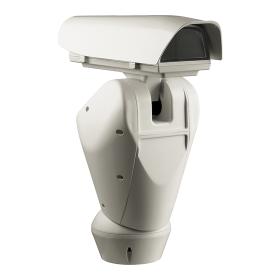
Outdoor p&t for highest precision day/night monitoring
Vorschau ausblenden Andere Handbücher für ULISSE:
Inhaltsverzeichnis

Werbung

Verfügbare Sprachen
  • DE

Verfügbare Sprachen

  • DEUTSCH, seite 245
Outdoor P&T for highest precision Day/Night monitoring
English - Instructions manual
EN
IT
Italiano - Manuale di istruzioni
FR
Français - Manuel d'instructions
DE
Deutsch - Bedienungslanleitung
RU
Русский - Руководство по эксплуатации
ULISSE

Werbung

Inhaltsverzeichnis
loading

Inhaltszusammenfassung für Videotec ULISSE

  • Seite 1 ULISSE Outdoor P&T for highest precision Day/Night monitoring English - Instructions manual Italiano - Manuale di istruzioni Français - Manuel d’instructions Deutsch - Bedienungslanleitung Русский - Руководство по эксплуатации...
  • Seite 3 ULISSE Outdoor P&T for highest precision Day/Night monitoring English - Instructions manual...
  • Seite 5: Inhaltsverzeichnis

    Contents ENGLISH 1 About this manual ......................7 1.1 Typographical conventions ..........................7 2 Notes on copyright and information on trademarks ..........7 3 Safety rules........................7 4 Identification ........................ 10 4.1 Product description and type designation....................10 4.2 Product markings ..............................10 4.2.1 Checking the markings ...............................10 5 Versions ........................
  • Seite 6 8.7.1 Fitting the bracket .................................26 8.7.2 Fitting the illuminator on the bracket ..........................26 8.8 Connection of the LED illuminators ........................27 8.9 Connection for cameras and LED illuminators synchronisation............28 8.10 Desiccant bag ...............................28 8.11 Setting of the LED illuminators and synchronization mode with the camera ......28 8.11.1 Description of the LED illuminator ..........................28 8.11.2 Synchronisation with an external twilight switch ....................29 8.11.3 Synchronising the unit with the LED illuminators ....................29...
  • Seite 7 10.1.8.3 Masking Menu (Edit Masks) ..................................45 10.1.8.4 How to create a new mask ..................................46 10.1.8.5 How to modify a mask ....................................47 10.1.8.6 Advanced Setting Menu ..................................47 10.1.8.7 Advanced Setting Menu (Zoom) ................................48 10.1.8.8 Advanced Setting Menu (Focus) .................................48 10.1.8.9 Advanced Setting Menu (Exposure) ..............................49 10.1.8.10 Advanced Setting Menu (Infrared) ..............................50 10.1.8.11 Advanced Setting Menu (White Balance) .............................51 10.1.8.12 Advanced Setting Menu (Other) ..............................51...
  • Seite 8 14.2 Cleaning the germanium window ........................64 15 Disposal of waste materials ..................64 16 Troubleshooting ......................65 17 Technical data ......................67 17.1 General ..................................67 17.2 Mechanical ................................67 17.3 Electrical/Video ..............................67 17.4 Camera ..................................68 17.5 Communications ..............................69 17.6 Protocols .................................69 17.7 Environment................................69 17.8 Certifications .................................69 18 Technical drawings ....................
  • Seite 9: About This Manual

    1 About this manual 3 Safety rules Before installing and using this unit, please read this CAUTION! The electrical system to which manual carefully. Be sure to keep it handy for later the unit is connected must be equipped reference. with a 20A max automatic bipolar circuit breaker.
  • Seite 10 • Before starting any operation, make sure the • Use a Class 2 listed UL tranformer, compliant with power supply is disconnected. the Standards in force, only for products marked UL, powered at 24Vac. • Do not use cables that seem worn or old. •...
  • Seite 11 • Do not allow children or unauthorised people to • Take all necessary precautions to prevent the use the appliance. apparatus from being damaged by electrostatic discharge. • The appliance should only be considered switched off when the power supply has been disconnected •...
  • Seite 12: Identification

    Pan & tilt devices have a label complying with CE markings. designation ULISSE ensures maximum surveillance coverage in all outdoor environments, even the most difficult. It can operate 24 hours a day in demanding security applications, without requiring maintenance work.
  • Seite 13: Versions

    24Vac. The product can be equipped with a wiper. The pan & tilt can be fitted with bracket for 2 VIDEOTEC LED illuminators for night surveillance (illuminators not included). Fig. 2 For further information refer to the relative chapter (12.7 Enabling the wiper (Wiper),...
  • Seite 14: Preparing The Product For Use

    6 Preparing the product for 6.3 Contents Check the contents to make sure they correspond with the list of materials as below: Any change that is not expressly approved • Positioning unit by the manufacturer will invalidate the • Power supply base guarantee.
  • Seite 15: Preparatory Work Before Installation

    6.5 Preparatory work before 6.5.2 Cables management installation The connection cables should not be accessible from the outside. It is necessary 6.5.1 Attaching the bracket to fasten the cables securely to the support in order to prevent excessive weight pulling Different types of supports are available (11 them out accidentaly.
  • Seite 16: Assembly

    7 Assembly 7.1.1 How to install the camera It is necessary to insulate the camera body 7.1 How to open the housing from the attachment slide in order to prevent interference with the video signal. Loosen the 2 screws on the side, turn the cover and the upper half of the body about the opening hinge Take out the inner support slide (01) loosening the axis.
  • Seite 17: Housing Board Description

    7.2 Housing board description 7.2.1 Connection of the camera and motorised lens BOARD DESCRIPTION All connections illustrated below should Connector/Terminal Function be made only and exclusively by expert BNC connector, video signal from installers who should comply with all the the camera wiring and power supply specifications for Motorised lens motor control...
  • Seite 18: Adjustment Of The Supply Voltage Of The Lens Motors

    Lenses with reverse polarity motors: Implement Camera: Implement the connections, as shown in the connections, as shown in the figure.. the figure.. FOCUS + 232 TX FOCUS - 232 RX IRIS + IRIS - 485_B ZOOM + 485_A ZOOM - Serial S_GND Video...
  • Seite 19: Installation

    8 Installation 8.1 Connecting the cables to the base Never, under any circumstances, make any changes or connections that are not Insert the cables into the cable glands holding the shown in this handbook. Failure to follow base at about 20cm from the support. Tighten the the connection instructions that are given cable glands.
  • Seite 20: Fixing The Base To The Support

    8.2 Fixing the base to the support Align the 3 notches on the base with those on the support as shown in the following figure. Use the screws and the washers supplied with the base. Once you have positioned the gasket (01), fix the base (02) onto the bracket (03) with screws (04), serrated washers (05) and screw rings (06).
  • Seite 21: Connector Board Description

    8.3 Connector board description CONNECTOR BOARD DESCRIPTION Connector/ Function CONNECTOR BOARD DESCRIPTION Component Connector/ Function Board power supply Component Signal cables Board power supply RS-232 Signal cables Fuse RS-232 Fuse Fuse Tab. 6 Version with LED illuminators. Fuse Tab. 5 Standard version.
  • Seite 22: Connection Of The Power Supply Line

    8.4 Connection of the power Earth cable should be about 10mm longer supply line than the other two, so that it will not be disconnected accidentally if pulled. Depending on the version, the device can be provided with different power supply voltages. Their The power supply cable should also be value is shown on the product identification label (4.2 covered by the silicone sheath (01) supplied...
  • Seite 23: 24Vac Power Line Connection

    8.4.1 24Vac power line connection 8.4.2 120Vac and 230Vac power line connection Use a Class 2 listed UL tranformer, Cut the cables to the correct length and make the compliant with the Standards in force, only connections. Connect the power supply to the for products marked UL, powered at 24Vac.
  • Seite 24: Signal Cable Connection

    8.5 Signal cable connection Connect the screen and central cable respectively to the GND and VIDEO All signal cables must be grouped together terminals. The terminals accept cables with by means of a strap. sections between 0.5mm² (AWG 20) and 0.08mm²...
  • Seite 25: Telemetry Lines Connections

    8.5.2 Telemetry lines connections CAUTION! TNV-1 installation type. The installation is type TNV-1, do not connect it to SELV circuits. CAUTION! In order to reduce the risk of fire, only use UL Listed or CSA certified cables sizes greater than or equal to 0.13mm² (26 AWG).
  • Seite 26: Connection Of The Alarm Inputs, Of The Twilight Switch And Of The Relays

    8.5.3 Connection of the alarm inputs, of Version with LED illuminators the twilight switch and of the relays CAUTION! TNV-1 installation type. The installation is type TNV-1, do not connect it to SELV circuits. CAUTION! In order to reduce the risk of fire, only use UL Listed or CSA certified cables AL1 AL2 LNO sizes greater than or equal to 0.13mm²...
  • Seite 27: Fixing The Upper Body

    8.6 Fixing the upper body Fix the upper body (01) to the base (02) using the fixing screws (03) equipped with gaskets (04). Make sure the base seal is present and in good condition (05). Pay attention to the fixing. Tightening torque: 4Nm.
  • Seite 28: Led Illuminators Installation

    (02). From Pan & Tilt, it is only possible to install VIDEOTEC illuminators. 8.7.1 Fitting the bracket Position the bracket (01) on the bottom of the housing as shown in figure. Install the screws and the washers (02) in the holes (03) and tighten them.
  • Seite 29: Connection Of The Led Illuminators

    8.8 Connection of the LED Connect the cables as shown in figure. illuminators Open the housing as described (Fig. 8, page 14). Insert the power supply cables through the cable glands by at least 25 cm. 25cm 25cm Left illuminator Right illuminator Fig.
  • Seite 30: Connection For Cameras And Led Illuminators Synchronisation

    8.9 Connection for cameras and 8.11 Setting of the LED LED illuminators synchronisation illuminators and synchronization mode with the camera No further connections are necessary for P&T units fitted with integrated module. Once the adjustment is done the illuminator on the left (MASTER) ZFI cameras fitted with infrared filter: Connect synchronizes and controls the illuminator the camera’s Day/Night mode switching input to...
  • Seite 31: Synchronisation With An External Twilight Switch

    8.11.2 Synchronisation with an external • For the unit with integrated module set the External value to the IR Probe entry of the Infrared twilight switch menu (10.1.8.10 Advanced Setting Menu (Infrared), To synchronise the illuminators and camera with an page 50).
  • Seite 32: Synchronising The Unit With The Camera Module

    8.11.4 Synchronising the unit with the 8.11.5 Synchronising the unit with the camera module LED illuminators To synchronise the unit with the camera module: To synchronise the unit with the LED illuminators it is necessary to: • Adjust the left illuminator (MASTER): •...
  • Seite 33: Manually Activate The Led Illuminators

    8.11.6 Manually activate the LED • Set the Off value under IR Probe in the Main menu > Block camera > Advanced > Infrared menu ( illuminators 10.1.8.10 Advanced Setting Menu (Infrared), page  To turn on the LED illuminators: 50). •...
  • Seite 34: Led Illuminator Switching On Threshold Adjustment

    8.11.7 LED illuminator switching on 8.11.8 LED illuminator power threshold adjustment adjustment The illuminator on the right must always be The illuminator on the right must always be set to maximum brightness. set to minimum power. The illuminator is set in the factory to provide maximum power.
  • Seite 35: Hardware Configuration

    OFF OFF OFF OFF ON ON ON OFF DYNAMICS VISTA OFF OFF OFF ON OFF OFF ON ON Tab. 14 Deafult configuration: MACRO (VIDEOTEC), 115200 Fig. 58 baud, RS-232, Address 1. This option does not require the setting of the DIP-switch (DIP1, DIP3). Tab. 15...
  • Seite 36: Dip3 Configuration

    8.12.4 DIP3 configuration 8.12.5 DIP4 configuration When the switch rocker is up it represents This DIP is set following the inverse the value 1 (ON). When the dip-switch procedure compared to those previously rocker is down it represents the value 0 performed.
  • Seite 37: Installation Examples

    Control RS-485-1 RS-485-2 keyboard TX/RX Fig. 64 This function is only available for bi- This function is only available for bi- directional protocols (example: PELCO, directional protocols (example: PELCO, AMERICAN DYNAMICS, VIDEOTEC MACRO, AMERICAN DYNAMICS, VIDEOTEC MACRO, etc.). etc.). MNVCUPTDMB_1511_EN...
  • Seite 38: Switching On

    9 Switching on 9.1 First start-up The first time the device is switched on we Make sure that the unit and other recommend making sure it is configured correctly. components of the installation are closed Before providing power supply, remove the DIP so that it is impossible to come into contact protection doors and position the firmware update with live parts.
  • Seite 39: Configuration

    10 Configuration 10.1.1.2 How to move around the menus Each page of the OSM shows a list of parameters 10.1 OSM interface (On Screen or sub-menus that can be selected by the operator. Move the cursor with the joystick (up and down) to Menu) scroll the various parameters .
  • Seite 40: How To Modify The Parameters

    10.1.1.3 How to modify the parameters 10.1.1.4 How to change the numeric fields Move the cursor to the parameter to be changed and Move the cursor to the parameter to be changed and confirm. The field will start flashing, indicating that it confirm.
  • Seite 41: How To Change Text

    10.1.1.5 How to change text The Confirm command (Zoom Tele) inserts the desired character. Move the cursor to the parameter to be changed and confirm. EDIT TEXT: AREA ------------------------ EDIT ZONE Text: TEXT AREA1 ------------------------ ↑ 1 NR A B C D E F G ERASE 2 START:+ 0.00...
  • Seite 42: Configuration Via Osm

    10.1.2 Configuration via OSM 10.1.5 ZFI Parameter Menu The screens for configuring the product are Zoom: This sets the maximum zoom level that illustrated below. the motorised lens can achieve. Common Wire: If enabled, it manages the 10.1.3 Main Menu motorised common wire lenses;...
  • Seite 43: Zone Titling Menu

    10.1.5.1 Zone Titling Menu Example: To enable titling of zone 1 when the device is between +15° and +45°, it is necessary to: This function allows setting up to eight (variable • Enable area titling by setting Y as the value of dimension) areas with titling option.
  • Seite 44: Zone Masking Menu

    10.1.5.2 Zone Masking Menu Example: To enable masking of zone 1 when the device is in the +15° and +45° position, proceed as This function allows setting up to eight masks follows: (variable dimension) with titling option. • Select 1 as value of parameter No. Number: Selects the area to be edited.
  • Seite 45: Housing Serial Port Menu

    10.1.6 Housing Serial Port Menu 10.1.7 Polarity Menu It allows you to configure the following parameters: Once you have exited from the camera Zoom: It allows you to choose the motor OSM, press the Iris Close key to return to rotation polarity of the lens Zoom.
  • Seite 46: Block Camera Menu

    10.1.8 Block Camera menu Example: To enable titling of zone 1 when the device is between +15° and +45°, it is necessary to: Area Titling: Allows access to the area titling • Enable area titling by setting Y as the value of submenu.
  • Seite 47: Masking Menu

    10.1.8.2 Masking Menu 10.1.8.3 Masking Menu (Edit Masks) Dynamic masking allows the creation of up to a It allows you to configure the following parameters: maximum of 24 masks so as to obtain the masking of Mask Number: Allows you to choose the mask certain areas defined by the user.
  • Seite 48: How To Create A New Mask

    10.1.8.4 How to create a new mask • When the desired result is obtained press the Iris Open. Choose a disabled mask by selecting Mask Number from the Edit Masks menu. Select Edit Mask to edit it ( Fig. 92, page 45). MASK 1 PTZ Motions Enabled In the following example we shall mask a flower.
  • Seite 49: How To Modify A Mask

    10.1.8.5 How to modify a mask 10.1.8.6 Advanced Setting Menu Choose an enabled mask by selecting Mask Number This menu is used to configure the SONY module. from the Edit Masks menu (Fig. 92, page 45). Select Zoom: Allows access to the Zoom submenu. Edit Mask to edit it.
  • Seite 50: Advanced Setting Menu (Zoom)

    10.1.8.7 Advanced Setting Menu (Zoom) 10.1.8.8 Advanced Setting Menu (Focus) Zoom Speed: Sets the speed of the zoom. The It allows you to configure the following parameters: speed ranges between 0 (minimum speed) and Focus Speed: Sets the speed of the Focus. The 7 (maximum speed).
  • Seite 51: Advanced Setting Menu (Exposure)

    10.1.8.9 Advanced Setting Menu (Exposure) The following table shows the inserted values with the corresponding effects on the SONY module lens. It allows you to configure the following parameters: CORRESPONDING VALUES/EFFECTS ON THE SONY 1-5. Mode: Sets the type of exposure control MODULE LENS Automatic, Manual, Shutter, Iris and Bright.
  • Seite 52: Advanced Setting Menu (Infrared)

    10.1.8.10 Advanced Setting Menu (Infrared) To avoid false switching, we recommend It allows you to configure the following parameters: choosing the higher day switching IR Probe: Signals the presence of a probe to threshold and delay values. manage the switching of the motorised lens from the Day to the Night mode.
  • Seite 53: Advanced Setting Menu (White Balance)

    10.1.8.11 Advanced Setting Menu (White 10.1.8.12 Advanced Setting Menu (Other) Balance) Sharpness: Sets the sharpness value of the image. It allows you to configure the following parameters: High Resolution: Enables the High Resolution Mode: Sets the type of control on White function.
  • Seite 54: Movement Menu

    10.1.9 Movement Menu 10.1.9.1 Manual Control Menu Maximum Speed: Select the maximum manual Offset Pan: The pan & tilt has a mechanically speed. defined 0° position. The Offset Pan function allows the definition of a different 0° position Speed With Zoom: When enabled, this using software.
  • Seite 55: Manual Control Menu

    10.1.9.2 Manual Control Menu (Limits) 10.1.9.4 Preset Menu (Edit Preset) It allows you to configure the following parameters: It allows you to configure the following parameters: Pan Limits: Enables the limits of Pan. Number: The Preset number to be edited. Pan Start: Sets the start limit of Pan.
  • Seite 56: Preset Menu (Utility Preset)

    10.1.9.5 Preset Menu (Utility Preset) 10.1.9.6 Patrol Menu It allows you to configure the following parameters: First Preset: First preset of the Patrol sequence. Scan Speed: Speed used to reach the Preset Last Preset: Last preset of the Patrol sequence. position after reception of a Scan control.
  • Seite 57: Motion Recall Menu

    10.1.9.8 Motion Recall Menu 10.1.10 Display Menu The unit can be configured so that, after a period of Actual Position: Is not set to OFF, you are able non-use, it carries out a movement function selected to select the display mode of the Pan, Tilt, Zoom, by the operator.
  • Seite 58: Digital I/O Menu

    10.1.11 Digital I/O Menu The single alarms menu allows you to configure the following values: Alarms: Access the alarm menu. Type: Type of contact, normally closed (N.C.) or Washer: Access the Washing System menu. normally open (N.O.). Action: The type of action carried out by P&T DIGITAL I/O when the alarm triggers (Off, Msg, PTZ Stop, ------------------------...
  • Seite 59: Washer Menu

    10.1.11.2 Washer Menu 10.1.12 Default Menu The P&T offers the possibility to use a wiper and to Delete Setup?: Resets all the parameters except operate a pump to clean the glass. the Presets. To configure the Washer put the lens of the camera in Delete Preset?: Deletes all previously stored front of the nozzle of the Washer.
  • Seite 60: Accessories

    11 Accessories 11.1.1 Washing system connection CAUTION! TNV-1 installation type. The For further details on configuration and installation is type TNV-1, do not connect it use, refer to the relative manual. to SELV circuits. 11.1 Washer CAUTION! In order to reduce the risk of fire, only use UL Listed or CSA certified cables The P&T can be equipped with an external pump that sizes greater than or equal to 0.13mm²...
  • Seite 61: Wall Mount

    11.2 Wall mount 11.4 Power supply with illuminator control Wall bracket with internal cable channel. Weather-proof box with power supply and control of the illuminators. Fig. 125 Fig. 127 Version of the standard box. 11.3 Parapet bracket Parapet bracket with internal cable channel. Fig.
  • Seite 62: Instructions For Normal Operation

    12 Instructions for normal 12.2 Saving a Preset operation The current position can be saved using the control device being used (for additional information refer to 12.1 Visualizing the state of the the manual of the device being used). 12.3 Restore a Preset position pan &...
  • Seite 63: Autopan Enabling

    12.6 Autopan enabling 12.8 Enabling the washer (Washer) The Autopan function loads the 2 saved Presets in a continuous manner. When a control is provided, the Pan & Tilt is To activate/deactivate this function, refer to the positioned with the window in front of the nozzle.. manual of the control device used or to the relative The pump and wiper are activated for a set period of chapter (12.11 Special controls, page 62).
  • Seite 64: Special Controls

    12.11 Special controls SPECIAL CONTROLS Control Protocol AMERICAN DYNA- PANASONIC PELCO D VIDEOTEC MACRO VISTA MICS Wiper Start Save Preset 85 Save Preset 85 Save Preset 85 Save Preset 85 Save Preset 85 Aux 3 ON Save Preset 54 Aux 3 ON...
  • Seite 65: Special Configurations

    12.12 Special configurations SPECIAL CONFIGURATIONS Configuration Protocol AMERICAN DYNA- PANASONIC PELCO D VIDEOTEC VISTA MICS MACRO Washer Configura- Save Preset 72 Save Preset 72 Save Preset 72 Save Preset 72 Save Preset 72 tion 1 (short wash) Washer Configura- Save Preset 73...
  • Seite 66: Maintaining

    13 Maintaining 14 Cleaning 14.1 Window and plastic cover Maintenance must be carried out by personnel trained to operate on electrical cleaning circuits. Avoid ethyl alcohol, solvents, hydrogenated 13.1 Fuses replacement hydrocarbide, strong acid and alkali. Such products may irreparably damage the Maintenance must be performed with the surface.
  • Seite 67: Troubleshooting

    16 Troubleshooting A blue display appears instead PROBLEM of the footage with the Ask for assistance from skilled personnel if: following indication: No Video • The unit is damaged after being dropped; Signal!!!. • There is noticeable deterioration in performance Incorrect wiring of the camera or CAUSE of the unit.
  • Seite 68 A display such as that shown Error E2:AUTOPAN PROBLEM PROBLEM below appears instead of the CONFIGURATION. footage: The two presets used as limits have CAUSE not been saved. INFO The two presets used as limits have ------------------------ not been enabled. Device ID: 00001 Type : Rs485 only Rx...
  • Seite 69: Technical Data

    Maximum number of presets for protocol: 250 Unit weight: 16.3kg (36lb) (16.8kg (37lb), with LED (VIDEOTEC MACRO) illuminators bracket) 15 characters string for Area and Preset titling ULISSE, for thermal cameras: Configuration through OSD Germanium window • Dimensions (Ø): 70mm (2.8in) (external), 55mm (2.1in) (internal) •...
  • Seite 70: Camera

    17.4 Camera DAY/NIGHT CAMERA FEATURES Day/Night 36x Day/Night 28x High sensitivity NTSC NTSC Optical zoom Wide Dynamic Range (Fix/Auto) – True progressive SCAN – Digital image stabilisation White balance Auto, ATW, Indoor, Outdoor (Fix/ Auto, ATW, Indoor, Outdoor (Fix/ Auto), Sodium Vapor Lamp (Fix/ Auto), Sodium Vapor Lamp (Fix/ Auto) Auto)
  • Seite 71: Communications

    17.8 Certifications The product may be interfaced with devices not manufactured by VIDEOTEC. It is possible that the interface protocols have changed or are in a different configuration from earlier tested units by VIDEOTEC. Electrical safety (CE): EN60950-1, IEC60950-1 VIDEOTEC recommends a test prior to installation.
  • Seite 72: Technical Drawings

    18 Technical drawings The dimensions of the drawings are in millimetres. Fig. 130 ULISSE. MNVCUPTDMB_1511_EN...
  • Seite 73 Fig. 131 ULISSE, pre-arranged version for two LED illuminators installation. MNVCUPTDMB_1511_EN...
  • Seite 74 Fig. 132 ULISSE, version for thermal cameras. MNVCUPTDMB_1511_EN...
  • Seite 75 INTEGRATED WIPER INTEGRATED WIPER, REINFORCED HEATER USABLE AREA USABLE USABLE USABLE AREA AREA AREA G - G H - H H - H REVERSED SLIDE, REVERSED SLIDE, INTEGRATED WIPER INTEGRATED WIPER, REINFORCED HEATER USABLE AREA Fig. 133 ULISSE, housing. MNVCUPTDMB_1511_EN...
  • Seite 76: A Appendix - Address Table

    A Appendix - Address table When the switch rocker is up it represents the value 1 (ON). When the dip-switch rocker is down it represents the value 0 (OFF). All possible combinations are shown below. ADDRESS CONFIGURATION (DIP 3) SW 8 SW 7 SW 6 SW 5...
  • Seite 77 ADDRESS CONFIGURATION (DIP 3) SW 8 SW 7 SW 6 SW 5 SW 4 SW 3 SW 2 SW 1 Address Address 39 Address 40 Address 41 Address 42 Address 43 Address 44 Address 45 Address 46 Address 47 Address 48 Address 49 Address 50 Address 51...
  • Seite 78 ADDRESS CONFIGURATION (DIP 3) SW 8 SW 7 SW 6 SW 5 SW 4 SW 3 SW 2 SW 1 Address Address 83 Address 84 Address 85 Address 86 Address 87 Address 88 Address 89 Address 90 Address 91 Address 92 Address 93 Address 94 Address 95...
  • Seite 79 ADDRESS CONFIGURATION (DIP 3) SW 8 SW 7 SW 6 SW 5 SW 4 SW 3 SW 2 SW 1 Address Address 127 Address 128 Address 129 Address 130 Address 131 Address 132 Address 133 Address 134 Address 135 Address 136 Address 137 Address 138 Address 139...
  • Seite 80 ADDRESS CONFIGURATION (DIP 3) SW 8 SW 7 SW 6 SW 5 SW 4 SW 3 SW 2 SW 1 Address Address 171 Address 172 Address 173 Address 174 Address 175 Address 176 Address 177 Address 178 Address 179 Address 180 Address 181 Address 182 Address 183...
  • Seite 81 ADDRESS CONFIGURATION (DIP 3) SW 8 SW 7 SW 6 SW 5 SW 4 SW 3 SW 2 SW 1 Address Address 215 Address 216 Address 217 Address 218 Address 219 Address 220 Address 221 Address 222 Address 223 Address 224 Address 225 Address 226 Address 227...
  • Seite 82 Email: info@videotec.com Tel. +33 1 60491816 - Fax +33 1 69284736 Email: info.fr@videotec.com Asia Pacific Videotec (HK) Ltd Americas Videotec Security, Inc. Flat 8, 19/F. On Dak Industrial Building, No. 2-6 Wah Sing Street Gateway Industrial Park, 35 Gateway Drive, Suite 100 Kwai Chung, New Territories - Hong Kong Plattsburgh, NY 12901 - U.S.A.
  • Seite 83 ULISSE Brandeggio da esterni per monitoraggio Day/ Night di massima precisione Italiano - Manuale di istruzioni...
  • Seite 85 Sommario ITALIANO 1 Informazioni sul presente manuale ................7 1.1 Convenzioni tipografiche ............................. 7 2 Note sul copyright e informazioni sui marchi commerciali ........7 3 Norme di sicurezza ......................7 4 Identificazione ......................10 4.1 Descrizione e designazione del prodotto .....................10 4.2 Marcatura del prodotto ............................10 4.2.1 Controllo della marcatura ..............................10 5 Versioni .........................
  • Seite 86 8.7.1 Montaggio della staffa .................................26 8.7.2 Montaggio dell'illuminatore sulla staffa........................26 8.8 Collegamento degli illuminatori a LED ......................27 8.9 Collegamento per la sincronizzazione della telecamera con gli illuminatori a LED ......28 8.10 Sacchetto disidratante ............................28 8.11 Regolazione degli illuminatori a LED e modalità di sincronizzazione con la telecamera ..28 8.11.1 Descrizione dell'illuminatore a LED ..........................28 8.11.2 Sincronizzazione con un interruttore crepuscolare esterno ................29 8.11.3 Sincronizzare l’unità...
  • Seite 87 10.1.8.3 Menù Mascheratura (Modifica Maschere) ............................45 10.1.8.4 Come creare una nuova maschera..............................46 10.1.8.5 Come modificare una maschera .................................47 10.1.8.6 Menù Configurazioni Avanzate ................................47 10.1.8.7 Menù Configurazioni Avanzate (Zoom) ............................48 10.1.8.8 Menù Configurazioni Avanzate (Focus) ............................48 10.1.8.9 Menù Configurazioni Avanzate (Esposizione) ..........................49 10.1.8.10 Menù...
  • Seite 88 14.2 Pulizia della finestra in germanio ........................64 15 Smaltimento dei rifiuti ....................64 16 Risoluzione dei problemi ..................65 17 Dati tecnici ......................... 67 17.1 Generale .................................67 17.2 Meccanica ................................67 17.3 Elettrico/Video ..............................67 17.4 Telecamere ................................68 17.5 Comunicazioni ..............................69 17.6 Protocolli ................................69 17.7 Ambiente ................................69 17.8 Certificazioni .................................69 18 Disegni tecnici ......................
  • Seite 89: Informazioni Sul Presente Manuale

    1 Informazioni sul presente 3 Norme di sicurezza manuale ATTENZIONE! L’impianto elettrico al quale è collegata l’unità deve essere dotato di Prima di installare e utilizzare questa unità, leggere un interruttore di protezione bipolare attentamente questo manuale. Conservare questo automatico da 20A max. Tale interruttore manuale a portata di mano come riferimento futuro.
  • Seite 90 • Prima di eseguire qualsiasi operazione assicurarsi • Per i prodotti marcati UL alimentati a 24Vac, di togliere tensione al prodotto. utilizzare un trasformatore UL listed Classe 2, conforme alle normative vigenti. • Non utilizzare cavi con segni di usura o invecchiamento.
  • Seite 91 • Non permettere l’uso dell’apparecchio a bambini o • Adottare le dovute precauzioni per evitare di personale non autorizzato. danneggiare l’apparecchiatura con scariche elettrostatiche. • L’apparecchio si considera disattivato soltanto quando l’alimentazione è stata tolta e i cavi di • L’unità è stata realizzata per essere collegata collegamento con altri dispositivi sono stati con cavo tripolare.
  • Seite 92: Identificazione

    Sui brandeggi è applicata una etichetta conforme alla marcatura CE. del prodotto ULISSE garantisce la massima copertura di monitoraggio in ogni ambiente esterno anche il più difficile. Può funzionare 24 ore su 24 in impegnative applicazioni di sicurezza, senza richiedere interventi di manutenzione.
  • Seite 93: Versioni

    24Vac. Il prodotto può essere provvisto di tergicristallo. Il brandeggio può essere dotato di un supporto per montaggio di 2 illuminatori a LED VIDEOTEC per la visione notturna (illuminatori non inclusi). Fig. 2 Per ulteriori informazioni fare riferimento al relativo capitolo (12.7 Attivazione del...
  • Seite 94: Preparazione Del Prodotto Per L'utilizzo

    6 Preparazione del prodotto 6.3 Contenuto per l'utilizzo Controllare che il contenuto sia corrispondente alla lista del materiale sotto elencata: Qualsiasi cambiamento non espressamente • Unità di posizionamento approvato dal costruttore fa decadere la • Base di alimentazione garanzia. • Imballo degli accessori: •...
  • Seite 95: Lavoro Preparatorio Prima Dell'installazione

    6.5 Lavoro preparatorio prima 6.5.2 Passaggio cavi dell’installazione I cavi di collegamento non devono essere accessibili dall'esterno. I cavi devono essere 6.5.1 Fissaggio del supporto opportunamente fissati al sostegno per evitare che l'eccessivo peso ne comporti lo Sono disponibili diversi tipi di supporto (11 sfilamento accidentale.
  • Seite 96: Assemblaggio

    7 Assemblaggio 7.1.1 Installazione della telecamera È necessario isolare il corpo della 7.1 Apertura della custodia telecamera dalla slitta di fissaggio per evitare disturbi sul segnale video. Svitare le 2 viti poste sul fianco, far ruotare tettuccio e corpo superiore attorno all’asse delle cerniere di Estrarre la slitta interna d’appoggio (01) svitando le apertura.
  • Seite 97: Descrizione Della Scheda Della Custodia

    7.2 Descrizione della scheda 7.2.1 Collegamento della telecamera e dell’ottica motorizzata della custodia Tutti i collegamenti illustrati di seguito DESCRIZIONE DELLA SCHEDA devono essere eseguiti solo da installatori Connettore/Mors Funzione esperti e devono essere rispettate tutte le etto specifiche di cablaggio e di alimentazione Connettore BNC, segnale video dei dispositivi.
  • Seite 98: Regolazione Della Tensione Di Alimentazione Dei Motori Delle Ottiche

    Ottiche con motori ad inversione di polarità: Telecamera: Eseguire le connessioni come illustrato Eseguire le connessioni come illustrato in figura. in figura. FOCUS + 232 TX FOCUS - 232 RX IRIS + IRIS - 485_B ZOOM + 485_A ZOOM - Seriale S_GND Video...
  • Seite 99: Installazione

    8 Installazione 8.1 Collegamento dei cavi alla base Non effettuare per nessun motivo alterazioni o collegamenti non previsti Introdurre i cavi all’interno dei pressacavi tenendo la in questo manuale. Il mancato rispetto base a circa 20cm dal supporto. Serrare i pressacavi. delle indicazioni fornite nel manuale in I pressacavi sono adatti per cavi con diametro merito ai collegamenti può...
  • Seite 100: Fissaggio Della Base Al Supporto

    8.2 Fissaggio della base al Allineare le 3 tacche sulla base con quelle presenti sui supporti come illustrato nella figura seguente. supporto Utilizzare le viti e le rondelle fornite con la base. Dopo aver posizionato la guarnizione (01), fissare la base (02) sul supporto (03) utilizzando le viti (04), le rondelle dentellate (05) e gli anelli per vite (06).
  • Seite 101: Descrizione Della Scheda Connettori

    8.3 Descrizione della scheda DESCRIZIONE DELLA SCHEDA CONNETTORI connettori Connettore/ Funzione Compo- nente DESCRIZIONE DELLA SCHEDA CONNETTORI Alimentazione della scheda Connettore/ Funzione Cavi di segnale Compo- nente RS-232 Alimentazione della scheda Fusibile Cavi di segnale Fusibile RS-232 Tab. 6 Versione con illuminatori a LED. Fusibile Fusibile Tab.
  • Seite 102: Collegamento Della Linea Di Alimentazione

    8.4 Collegamento della linea di Il cavo di terra deve essere più lungo degli alimentazione altri due di circa 10mm per prevenirne il distacco accidentale a causa dello A seconda della versione, al dispositivo possono stiramento. essere fornite diverse tensioni di alimentazione. Il loro valore è...
  • Seite 103: Collegamento Della Linea Di Alimentazione In 24Vac

    8.4.1 Collegamento della linea di 8.4.2 Collegamento della linea di alimentazione in 24Vac alimentazione in 120Vac e 230Vac Tagliare a misura i cavi e realizzare i collegamenti. Per i prodotti marcati UL alimentati a 24Vac, Collegare la linea di alimentazione al seguente utilizzare un trasformatore UL listed Classe morsetto: J6.
  • Seite 104: Collegamento Dei Cavi Di Segnale

    8.5 Collegamento dei cavi di Collegare lo schermo e il cavo centrale segnale rispettivamente ai morsetti GND e VIDEO. I morsetti accettano cavi di sezione Tutti i cavi di segnale devono essere compresa tra 0.5mm² (AWG 20) e 0.08mm² raggruppati con una fascetta. (AWG 28).
  • Seite 105: Collegamento Delle Linee Di Telemetria

    8.5.2 Collegamento delle linee di telemetria ATTENZIONE! L'installazione è di tipo TNV-1. Non collegare a circuiti SELV. ATTENZIONE! Per ridurre il rischio di incendio usare solamente cavi certificati UL Listed o CSA aventi dimensioni maggiori o uguali a 0.13mm² (26 AWG). Fig.
  • Seite 106: Collegamento Degli Ingressi Di Allarme, Dell'interruttore Crepuscolare E Dei Relè

    8.5.3 Collegamento degli ingressi di Versione con illuminatori a LED allarme, dell'interruttore crepuscolare e dei relè ATTENZIONE! L'installazione è di tipo TNV-1. Non collegare a circuiti SELV. ATTENZIONE! Per ridurre il rischio di incendio usare solamente cavi certificati UL AL1 AL2 LNO Listed o CSA aventi dimensioni maggiori o AGND uguali a 0.13mm²...
  • Seite 107: Fissaggio Del Corpo Superiore

    8.6 Fissaggio del corpo superiore Fissare il corpo superiore (01) alla base (02) tramite le viti di fissaggio (03) dotate di guarnizioni (04). Controllare che sia presente e in buono stato la guarnizione della base (05). Prestare attenzione durante il fissaggio. Coppia di serraggio: 4Nm.
  • Seite 108: Montaggio Degli Illuminatori A Led

    Per un corretto funzionamento si devono sempre installare entrambi gli illuminatori. Sul brandeggio è possibile installare esclusivamente illuminatori VIDEOTEC. 8.7.1 Montaggio della staffa Posizionare la staffa (01) sulla parte inferiore della custodia come illustrato in figura. Inserire le viti e le rondelle (02) nei fori (03) e serrarle.
  • Seite 109: Collegamento Degli Illuminatori A Led

    8.8 Collegamento degli Collegare i cavi come illustrato in figura. illuminatori a LED Aprire la custodia come descritto (Fig. 8, pagina 14). Inserire i cavi di alimentazione per almeno 25cm attraverso i pressacavi. 25cm 25cm Illuminatore sinistro Illuminatore destro Fig. 43 COLLEGAMENTO DEGLI ILLUMINATORI A LED Fig.
  • Seite 110: Collegamento Per La Sincronizzazione Della Telecamera Con Gli Illuminatori A Led

    8.9 Collegamento per la 8.11 Regolazione degli sincronizzazione della illuminatori a LED e modalità telecamera con gli illuminatori a di sincronizzazione con la telecamera Per i brandeggi dotati di modulo integrato Una volta effettuata la regolazione non è necessario fare ulteriori collegamenti. l'illuminatore di sinistra (MASTER) sincronizza e controlla l'illuminatore di Telecamere ZFI dotate di filtro infrarosso:...
  • Seite 111: Sincronizzazione Con Un Interruttore Crepuscolare Esterno

    8.11.2 Sincronizzazione con un • Per l'unità con modulo integrato, impostare il valore Esterna alla voce Sonda IR del menù interruttore crepuscolare esterno Infrarosso (10.1.8.10 Menù Configurazioni Per sincronizzare gli illuminatori e la telecamera con Avanzate (Infrarosso), pagina 50). un crepuscolare esterno è necessario: •...
  • Seite 112: Sincronizzare L'unità Con Il Modulo Camera

    8.11.4 Sincronizzare l’unità con il 8.11.5 Sincronizzare l’unità con gli modulo camera illuminatori a LED Per sincronizzare l'unità con il modulo camera è Per sincronizzare l’unità con gli illuminatori a LED è necessario: necessario: • Regolare l'illuminatore sinistro (MASTER): • Regolare l'illuminatore sinistro (MASTER): •...
  • Seite 113: Attivazione Manuale Degli Illuminatori A Led

    8.11.6 Attivazione manuale degli • Associare il valore Off alla voce Sonda IR del menù Menù principale > Modalità camera > Avanzate illuminatori a LED > Infrarosso (10.1.8.10 Menù Configurazioni Se si desidera attivare l'illuminatore a LED è Avanzate (Infrarosso), pagina 50). necessario: •...
  • Seite 114: Regolazione Della Soglia Di Accensione Degli Illuminatori A Led

    8.11.7 Regolazione della soglia di 8.11.8 Regolazione della potenza degli accensione degli illuminatori a LED illuminatori a LED L'illuminatore destro deve sempre essere L'illuminatore destro deve sempre essere impostato a luminosità massima. impostato a potenza minima. L'illuminatore è regolato in fabbrica per erogare la massima potenza.
  • Seite 115: Configurazione Hardware

    OFF OFF OFF OFF ON ON ON OFF DYNAMICS VISTA OFF OFF OFF ON OFF OFF ON ON Tab. 14 Configurazione di default: MACRO (VIDEOTEC), 115200 baud, RS-232, Indirizzo 1. Questa opzione non richiede il settaggio dei DIP-switch (DIP1, DIP3). Fig. 58 Tab. 15...
  • Seite 116: Configurazione Del Dip3

    8.12.4 Configurazione del DIP3 8.12.5 Configurazione del DIP4 La levetta dello switch verso l'alto Il settaggio di questo DIP avviene in rappresenta il valore 1 (ON). La levetta maniera inversa dai precedenti. La levetta verso il basso rappresenta il valore 0 (OFF). dello switch verso l'alto rappresenta il valore 0 (OFF).
  • Seite 117: Esempi Di Installazione

    Tastiera di controllo RS-485-1 RS-485-2 controllo TX/RX Fig. 64 Questa funzione è disponibile soltanto con Questa funzione è disponibile soltanto con protocolli bidirezionali (esempio: PELCO, protocolli bidirezionali (esempio: PELCO, AMERICAN DYNAMICS, VIDEOTEC MACRO, AMERICAN DYNAMICS, VIDEOTEC MACRO, ecc.). ecc.). MNVCUPTDMB_1511_IT...
  • Seite 118: Accensione

    9 Accensione 9.1 Prima accensione Alla prima accensione è sempre utile verificare la Assicurarsi che l'unità e gli altri componenti corretta configurazione del dispositivo. dell’impianto siano chiusi in modo idoneo a Prima di fornire alimentazione, rimuovere lo impedire il contatto con componenti sotto sportellino di protezione dei DIP e posizionare su ON tensione.
  • Seite 119: Configurazione

    10 Configurazione 10.1.1.2 Come muoversi nei menù Ogni videata dell’OSM presenta una lista di parametri 10.1 Interfaccia OSM (On Screen o di sottomenù che possono essere selezionati dall’operatore. Per scorrere i vari parametri muovere il Menu) cursore agendo sul joystick (alto e basso). 10.1.1 Uso dell'OSM CONTROLLO MANUALE Durante il normale funzionamento dell'unità...
  • Seite 120: Come Modificare I Parametri

    10.1.1.3 Come modificare i parametri 10.1.1.4 Come modificare i campi numerici Spostarsi con il cursore in corrispondenza del Spostarsi con il cursore in corrispondenza del parametro che si intende modificare e confermare. parametro che si intende modificare e confermare. Il campo comincerà a lampeggiare indicando che è...
  • Seite 121: Come Modificare I Testi

    10.1.1.5 Come modificare i testi Il comando Conferma (Zoom Tele) inserisce il carattere desiderato. Spostarsi con il cursore in corrispondenza del parametro che si intende modificare e confermare. EDIT TEXT: AREA ------------------------ MODIFICA AREA Text: TEXT AREA1 ------------------------ ↑ 1 NR A B C D E F G ERASE 2 START:+...
  • Seite 122: Configurazione Tramite Osm

    10.1.2 Configurazione tramite OSM 10.1.5 Menù Parametri ZFI Di seguito verranno illustrate le schermate che Zoom: Imposta il numero massimo di servono a configurare il prodotto. ingrandimenti che può effettuare l'ottica motorizzata. 10.1.3 Menù Principale Filo Comune: Se abilitato, gestisce le ottiche Dal menù...
  • Seite 123: Menù Titolazione Aree

    10.1.5.1 Menù Titolazione Aree Esempio: Per attivare la titolazione dell’area 1 quando il dispositivo si trova tra +15° e +45° è Questa funzione consente di impostare fino a otto necessario: zone (di dimensioni variabili) con possibilità di • Abilitare la titolazione delle aree, impostando S titolazione.
  • Seite 124: Menù Mascheratura Aree

    10.1.5.2 Menù Mascheratura Aree Esempio: Per attivare la mascheratura dell’area 1 quando il dispositivo si trova tra +15° e +45° è Questa funzione consente di impostare fino a otto necessario: maschere (di dimensioni variabili) con possibilità di • Selezionare 1 come valore del parametro Nr. titolazione.
  • Seite 125: Menù Seriale Custodia

    10.1.6 Menù Seriale Custodia 10.1.7 Menù Polarità Permette di configurare i seguenti parametri: Una volta usciti dall’OSM della telecamera, Zoom: Permette di scegliere la polarità di premere il tasto Iris Close per tornare rotazione del motore dello Zoom dell'ottica. all’OSM del brandeggio. Focus: Permette di selezionare la polarità...
  • Seite 126: Menù Modulo Camera

    10.1.8 Menù Modulo Camera Esempio: Per attivare la titolazione dell’area 1 quando il dispositivo si trova tra +15° e +45° è Titolazione Aree: Permette di entrare nel necessario: sottomenù per la gestione della titolazione delle • Abilitare la titolazione delle aree, impostando S aree.
  • Seite 127: Menù Mascheratura

    10.1.8.2 Menù Mascheratura 10.1.8.3 Menù Mascheratura (Modifica Maschere) La mascheratura dinamica permette di creare fino ad un massimo di 24 maschere in modo da ottenere Permette di configurare i seguenti parametri: l’oscuramento di particolari aree definite dall’utente. Maschera Numero: Permette di scegliere su Le maschere vengono definite nello spazio e tengono quale maschera agire.
  • Seite 128: Come Creare Una Nuova Maschera

    10.1.8.4 Come creare una nuova maschera • Una volta ottenuto il risultato desiderato premere il pulsante Iris Open. Scegliere una maschera non abilitata selezionando dal menù Modifica Maschere la voce Maschera Numero. Per modificarla seleziona la voce Modifica MASK 1 Maschera (Fig.
  • Seite 129: Come Modificare Una Maschera

    10.1.8.5 Come modificare una maschera 10.1.8.6 Menù Configurazioni Avanzate Scegliere una maschera abilitata selezionando dal Accedendo a questo menù è possibile configurare il menù Modifica Maschere la voce Maschera Numero ( modulo SONY. Fig. 92, pagina 45). Per modificarla seleziona la voce Zoom: Permette di accedere al sottomenù...
  • Seite 130: Menù Configurazioni Avanzate (Zoom)

    10.1.8.7 Menù Configurazioni Avanzate 10.1.8.8 Menù Configurazioni Avanzate (Zoom) (Focus) Velocità Zoom: Imposta la velocità dello zoom. Permette di configurare i seguenti parametri: I valori di velocità sono compresi tra 0 (minima Velocità Focus: Imposta la velocità del Focus. velocità) e 7 (massima velocità). I valori di velocità...
  • Seite 131: Menù Configurazioni Avanzate (Esposizione)

    10.1.8.9 Menù Configurazioni Avanzate La tabella seguente riporta la corrispondenza tra i valori introdotti e l’effetto sull’ottica del modulo (Esposizione) SONY. Permette di configurare i seguenti parametri: CORRISPONDENZA VALORE/EFFETTO OTTICA 1-5. Modo: Imposta il tipo di controllo MODULO SONY dell’esposizione: Automatica, Manuale, Shutter, Iris e Bright.
  • Seite 132: Menù Configurazioni Avanzate (Infrarosso)

    10.1.8.10 Menù Configurazioni Avanzate Per evitare false commutazioni si consiglia (Infrarosso) di scegliere i valori di soglia e ritardo di Permette di configurare i seguenti parametri: commutazione diurna più elevati. Sonda IR: Segnala l’eventuale presenza di una sonda per la gestione del passaggio da modalità INFRAROSSO Day a Night dell'ottica motorizzata.
  • Seite 133: Menù Configurazioni Avanzate (Bilanciamento Bianco)

    10.1.8.11 Menù Configurazioni Avanzate 10.1.8.12 Menù Configurazioni Avanzate (Bilanciamento Bianco) (Altro) Permette di configurare i seguenti parametri: Nitidezza: Imposta il valore della nitidezza dell’immagine. Modo: Imposta il tipo di controllo del Alta Risoluzione: Abilita la funzione Alta bilanciamento del bianco. I valori possibili sono: Risoluzione.
  • Seite 134: Menù Movimento

    10.1.9 Menù Movimento 10.1.9.1 Menù Controllo Manuale Velocità Massima: Selezione della massima Offset Pan: Il brandeggio ha una posizione velocità manuale. di 0° definita meccanicamente. La funzione Offset Pan permette di definire via software una Velocità Con Zoom: Tale parametro, se abilitato, diversa posizione di 0°.
  • Seite 135: Menù Controllo Manuale (Limiti)

    10.1.9.2 Menù Controllo Manuale (Limiti) 10.1.9.4 Menù Preset (Modifica Preset) Permette di configurare i seguenti parametri: Permette di configurare i seguenti parametri: Limiti Pan: Abilita i limiti del Pan. Numero: Il numero del Preset che si desidera modificare. Pan Inizio: Imposta il limite iniziale del Pan. Abilitazione: L’abilitazione del preset.
  • Seite 136: Menù Preset (Utilità Preset)

    10.1.9.5 Menù Preset (Utilità Preset) 10.1.9.6 Menù Patrol Permette di configurare i seguenti parametri: Primo Preset: Primo preset della sequenza di Patrol. Velocità Scan: Velocità usata per raggiungere la posizione di Preset dopo la ricezione di un Ultimo Preset: L’ultimo preset della sequenza di comando di Scan.
  • Seite 137: Menù Richiamo Movimenti

    10.1.9.8 Menù Richiamo Movimenti 10.1.10 Menù Visualizzazioni È possibile configurare l'unità in modo che, dopo un Posizione Attuale: Se posto diverso da OFF, certo periodo di inattività, esegua automaticamente permette di selezionare la modalità con la quale una funzione di movimento scelta dall’operatore. sono visualizzate sullo schermo i valori di Pan, Tilt, Zoom, Focus ed Iris.
  • Seite 138: Menù I/O Digitali

    10.1.11 Menù I/O Digitali Nei menù dei singoli allarmi è possibile configurare i seguenti valori: Allarmi: Accesso al menù Allarmi. Tipo: Tipo di contatto, normalmente chiuso Impianto Di Lavaggio: Accesso al menù (N.C.) o normalmente aperto (N.O.) Impianto di Lavaggio. Azione: Il tipo di azione che il brandeggio effettua quando l’allarme si attiva (Off, Msg, PTZ I/O DIGITALI...
  • Seite 139: Menù Impianto Di Lavaggio

    10.1.11.2 Menù Impianto di Lavaggio 10.1.12 Menù Default Il brandeggio offre la possibilità di utilizzare un Cancella Setup?: Ripristina tutti i parametri tergicristallo e di azionare una pompa per la pulizia eccetto i preset. del vetro. Cancella Preset?: Elimina tutti i preset Per configurare l’impianto di lavaggio posizionare precedentemente memorizzati.
  • Seite 140: Accessori

    11 Accessori 11.1.1 Collegamento dell'impianto di lavaggio Per ulteriori dettagli sulla configurazione ATTENZIONE! L'installazione è di tipo TNV-1. e l’utilizzo fare riferimento al manuale del Non collegare a circuiti SELV. relativo accessorio. ATTENZIONE! Per ridurre il rischio di 11.1 Impianto di lavaggio incendio usare solamente cavi certificati UL Listed o CSA aventi dimensioni maggiori o Il brandeggio può...
  • Seite 141: Supporto Da Parete

    11.2 Supporto da parete 11.4 Alimentatore con controllo degli illuminatori Supporto per montaggio a parete con passaggio interno cavi. Scatola stagna con alimentatore e controllo degli illuminatori. Fig. 127 Versione della scatola standard. Fig. 125 11.3 Supporto da parapetto Supporto per montaggio a parapetto con passaggio interno cavi.
  • Seite 142: Istruzioni Di Funzionamento Ordinario

    12 Istruzioni di 12.2 Salvataggio di un Preset funzionamento ordinario Tramite il dispositivo di controllo utilizzato è possibile salvare la posizione attuale (per ulteriori informazioni 12.1 Visualizzazione dello stato fare riferimento al manuale del dispositivo utilizzato). 12.3 Richiamo di una posizione di del brandeggio Preset (Scan) Durante il normale funzionamento, a scelta...
  • Seite 143: Attivazione Dell'autopan

    12.6 Attivazione dell'Autopan 12.8 Attivazione dell'impianto di lavaggio (Washer) La funzione Autopan richiama in modo continuo i 2 preset memorizzati. Quando si invia il comando il brandeggio si posiziona Per attivare/disattivare la funzione fare riferimento con la finestra di fronte all'ugello. Si attivano la al manuale del dispositivo di controllo utilizzato o al pompa ed il tergicristallo per un tempo determinato.
  • Seite 144: Comandi Speciali

    12.11 Comandi speciali COMANDI SPECIALI Comando Protocollo AMERICAN DYNA- PANASONIC PELCO D VIDEOTEC MACRO VISTA MICS Wiper Start Salvare Preset 85 Salvare Preset 85 Salvare Preset 85 Salvare Preset 85 Salvare Preset 85 Aux 3 ON Salvare Preset 54 Aux 3 ON...
  • Seite 145: Configurazioni Speciali

    12.12 Configurazioni speciali CONFIGURAZIONI SPECIALI Configurazione Protocollo AMERICAN DYNA- PANASONIC PELCO D VIDEOTEC VISTA MICS MACRO Washer Configura- Salvare Preset 72 Salvare Preset 72 Salvare Preset 72 Salvare Preset 72 Salvare Preset 72 zione 1 (lavaggio corto) Washer Configura- Salvare Preset 73...
  • Seite 146: Manutenzione

    13 Manutenzione 14 Pulizia 14.1 Pulizia del vetro e delle parti La manutenzione deve essere eseguita solo da personale qualificato ad intervenire su in plastica circuiti elettrici. Evitare alcool etilico, solventi, idrocarburi 13.1 Sostituzione dei fusibili idrogenati, acidi forti e alcali. L’utilizzo di detti prodotti danneggia in modo Eseguire la manutenzione in assenza irreparabile la superficie trattata.
  • Seite 147: Risoluzione Dei Problemi

    16 Risoluzione dei problemi Non compare l’immagine PROBLEMA ripresa, ma una schermata blu Richiedere l’intervento di personale qualificato con l’indicazione: No Video quando: Signal!!!. • L’unità si è danneggiata a seguito di una caduta; Errato cablaggio della telecamera o CAUSA •...
  • Seite 148 Non compare l’immagine Errore E2:AUTOPAN PROBLEMA PROBLEMA ripresa, ma una schermata del CONFIGURATION. tipo: I due preset utilizzati come limiti CAUSA non sono stati memorizzati. INFO I due preset utilizzati come limiti ------------------------ non sono stati abilitati. Device ID: 00001 Type : Rs485 only Rx SOLUZIONE...
  • Seite 149: Dati Tecnici

    Stringa di 15 caratteri per titolazione dell'area e dei Peso unitario: 16.3kg (16.8kg, con supporto per preset illuminatori a LED) Configurabile da OSD ULISSE, per telecamere termiche: Finestra in germanio • Dimensioni (Ø): 70mm (esterno), 55mm (interno) • Spessore: 2mm • Trattamento esterno antigraffio: Hard Carbon Coating (DLC) •...
  • Seite 150: Telecamere

    17.4 Telecamere CARATTERISTICHE TELECAMERA DAY/NIGHT Day/Night 36x Day/Night 28x Alta sensibilità NTSC NTSC Zoom ottico Wide Dynamic Range (Fix/Auto) – True progressive SCAN – Stabilizzazione immagine digitale Bilanciamento del bianco Auto, ATW, Indoor, Outdoor (Fix/ Auto, ATW, Indoor, Outdoor (Fix/ Auto), Sodium Vapor Lamp (Fix/ Auto), Sodium Vapor Lamp (Fix/ Auto)
  • Seite 151: Comunicazioni

    Il prodotto può essere interfacciato con dispositivi non prodotti da Sicurezza elettrica (CE): EN60950-1, IEC60950-1 VIDEOTEC. È possibile che i loro protocolli siano cambiati o che questi siano stati modificati rispetto a quelli testati da VIDEOTEC. VIDEOTEC Compatibilità elettromagnetica (CE): EN50130-4, suggerisce un test prima di qualsiasi installazione.
  • Seite 152: Disegni Tecnici

    18 Disegni tecnici Le dimensioni dei disegni sono espresse in millimetri. Fig. 130 ULISSE. MNVCUPTDMB_1511_IT...
  • Seite 153 Fig. 131 ULISSE, versione con predisposizione per il montaggio di due illuminatori a LED. MNVCUPTDMB_1511_IT...
  • Seite 154 Fig. 132 ULISSE, versione per telecamere termiche. MNVCUPTDMB_1511_IT...
  • Seite 155 RISCALDAMENTO POTENZIATO AREA UTILE AREA AREA AREA UTILE UTILE UTILE G - G H - H H - H SLITTA IN POSIZIONE ROVESCIATA, SLITTA IN POSIZIONE ROVESCIATA, TERGICRISTALLO INTEGRATO TERGICRISTALLO INTEGRATO, RISCALDAMENTO POTENZIATO AREA UTILE Fig. 133 ULISSE, custodia. MNVCUPTDMB_1511_IT...
  • Seite 156: A Appendice - Tabella Degli Indirizzi

    A Appendice - Tabella degli indirizzi La levetta dello switch verso l'alto rappresenta il valore 1 (ON). La levetta verso il basso rappresenta il valore 0 (OFF). Di seguito sono riportate tutte le combinazioni possibili. CONFIGURAZIONE DELL'INDIRIZZO (DIP 3) SW 8 SW 7 SW 6 SW 5...
  • Seite 157 CONFIGURAZIONE DELL'INDIRIZZO (DIP 3) SW 8 SW 7 SW 6 SW 5 SW 4 SW 3 SW 2 SW 1 Indirizzo Indirizzo 39 Indirizzo 40 Indirizzo 41 Indirizzo 42 Indirizzo 43 Indirizzo 44 Indirizzo 45 Indirizzo 46 Indirizzo 47 Indirizzo 48 Indirizzo 49 Indirizzo 50 Indirizzo 51...
  • Seite 158 CONFIGURAZIONE DELL'INDIRIZZO (DIP 3) SW 8 SW 7 SW 6 SW 5 SW 4 SW 3 SW 2 SW 1 Indirizzo Indirizzo 83 Indirizzo 84 Indirizzo 85 Indirizzo 86 Indirizzo 87 Indirizzo 88 Indirizzo 89 Indirizzo 90 Indirizzo 91 Indirizzo 92 Indirizzo 93 Indirizzo 94 Indirizzo 95...
  • Seite 159 CONFIGURAZIONE DELL'INDIRIZZO (DIP 3) SW 8 SW 7 SW 6 SW 5 SW 4 SW 3 SW 2 SW 1 Indirizzo Indirizzo 127 Indirizzo 128 Indirizzo 129 Indirizzo 130 Indirizzo 131 Indirizzo 132 Indirizzo 133 Indirizzo 134 Indirizzo 135 Indirizzo 136 Indirizzo 137 Indirizzo 138 Indirizzo 139...
  • Seite 160 CONFIGURAZIONE DELL'INDIRIZZO (DIP 3) SW 8 SW 7 SW 6 SW 5 SW 4 SW 3 SW 2 SW 1 Indirizzo Indirizzo 171 Indirizzo 172 Indirizzo 173 Indirizzo 174 Indirizzo 175 Indirizzo 176 Indirizzo 177 Indirizzo 178 Indirizzo 179 Indirizzo 180 Indirizzo 181 Indirizzo 182 Indirizzo 183...
  • Seite 161 CONFIGURAZIONE DELL'INDIRIZZO (DIP 3) SW 8 SW 7 SW 6 SW 5 SW 4 SW 3 SW 2 SW 1 Indirizzo Indirizzo 215 Indirizzo 216 Indirizzo 217 Indirizzo 218 Indirizzo 219 Indirizzo 220 Indirizzo 221 Indirizzo 222 Indirizzo 223 Indirizzo 224 Indirizzo 225 Indirizzo 226 Indirizzo 227...
  • Seite 162 Email: info@videotec.com Tel. +33 1 60491816 - Fax +33 1 69284736 Email: info.fr@videotec.com Asia Pacific Videotec (HK) Ltd Americas Videotec Security, Inc. Flat 8, 19/F. On Dak Industrial Building, No. 2-6 Wah Sing Street Gateway Industrial Park, 35 Gateway Drive, Suite 100 Kwai Chung, New Territories - Hong Kong Plattsburgh, NY 12901 - U.S.A.
  • Seite 163 ULISSE Tourelle extérieures pour la surveillance Day/Night de grande précision Français - Manuel d’instructions...
  • Seite 165 Sommaire FRANÇAIS 1 À propos de ce mode d’emploi ..................7 1.1 Conventions typographiques ..........................7 2 Notes sur le copyright et informations sur les marques de commerce ..... 7 3 Normes de securité ......................7 4 Identification ........................ 10 4.1 Description et désignation du produit ......................10 4.2 Marquage du produit ............................10 4.2.1 Contrôle du marquage ................................10...
  • Seite 166 8.7.1 Montage de l’étrier ................................26 8.7.2 Montage du projecteur sur l’étrier ..........................26 8.8 Branchement des projecteur à LED.........................27 8.9 Connexion pour la synchronisation des caméras avec les projecteurs à LED .........28 8.10 Sachet déshydratant ............................28 8.11 Reglage des projecteurs à LED et modalité de synchronisation avec la caméra ......28 8.11.1 Description du projecteur à...
  • Seite 167 10.1.8.3 Menu Masquage (Modifier Masques) ...............................45 10.1.8.4 Comment créer un nouveau masque ...............................46 10.1.8.5 Comment modifier un masque ................................47 10.1.8.6 Menu Configurations Avancées ................................47 10.1.8.7 Menu Configurations Avancées (Zoom) ............................48 10.1.8.8 Menu Configurations Avancées (Focus) ............................48 10.1.8.9 Menu Configurations Avancées (Esposition) ..........................49 10.1.8.10 Menu Configurations Avancées (Infrarouge)..........................50 10.1.8.11 Menu Configurations Avancées (Équilibre Blanc) ........................51 10.1.8.12 Menu Configurations Avancées (Autre) ............................51...
  • Seite 168 14.2 Nettoyage de la fenêtre au germanium ......................64 15 Élimination des déchets .................... 64 16 Dépannage ......................... 65 17 Données techniques ....................67 17.1 Généralités ................................67 17.2 Mécanique ................................67 17.3 Electrique/Video ..............................67 17.4 Caméra ..................................68 17.5 Communications ..............................69 17.6 Protocoles ................................69 17.7 Environnement ..............................69 17.8 Certifications .................................69 18 Dessins techniques ....................
  • Seite 169: Propos De Ce Mode D'emploi

    1 À propos de ce mode 3 Normes de securité d’emploi ATTENTION! Le circuit électrique auquel l'unité est reliée doit être équipé d'un Avant d’installer et d’utiliser cet appareil, veuillez interrupteur de protection bipolaire lire attentivement ce mode d’emploi. Conservez-le à automatique de 20A max.
  • Seite 170 • Sectionner l'alimentation avant de procéder à • Il faut, uniquement pour les produits marqués UL toute opération. alimentés à 24Vac, utiliser un transformateur UL listed Classe 2, conforme aux normes en vigueur. • Ne pas utiliser de câbles usés ou endommagés. •...
  • Seite 171 • Ne pas laisser l'appareil à portée des enfants ou de • Adopter les précautions utiles pour éviter personnes non autorisées. d'endommager l'appareil à la suite de décharges électrostatiques. • L’appareil ne doit être considéré comme désactivé qu'avec l'alimentation sectionnée et les câbles de •...
  • Seite 172: Identification

    4.1 Description et désignation du Les tourelles portent un étiquette conforme au marquage CE. produit ULISSE assure une couverture maximale de surveillance dans chaque environnement extérieur même le plus difficile. Il peut fonctionner 24 heures sur 24 dans des applications exigeantes en matière de sécurité, sans requérir des interventions de...
  • Seite 173: Versions

    24Vac. Le produit peut être équipé d’un essuie-glace. La tourelle peut être munie d’un support pour l’utilisation de 2 projecteurs à LED VIDEOTEC pour vision nocturne (projecteurs à prévoir en plus). Fig. 2 Pour d'autres renseignements se référer à le chapitre relatif (12.7 Validation de l’essuie-...
  • Seite 174: Préparation Du Produit En Vue De L'utilisation

    6 Préparation du produit en 6.3 Contenu vue de l’utilisation Contrôler que le contenu correspond à la liste matériel indiquée ci-dessous: Toute modification non approuvée • Unité de positionnement expressément par le fabricant entraînera • Base d'alimentation l’annulation de la garantie. •...
  • Seite 175: Opérations À Effectuer Avant L'installation

    6.5 Opérations à effectuer avant 6.5.2 Passage des câbles l’installation Les câbles de connexion ne doivent pas être accessibles de l'extérieur. Les câbles 6.5.1 Fixation du support doivent être fixés au support pour éviter que le poids excessif n'entraîne leur sortie Plusieurs types de supports sont disponibles (11 accidentelle.
  • Seite 176: Assemblage

    7 Assemblage 7.1.1 Installation de la caméra Il est nécessaire d'isoler le corps de la 7.1 Ouverture du caisson caméra de la glissière de fixation pour éviter toute perturbation du signal vidéo. Dévisser les 2 vis placées sur le côté, faire tourner le toit pare-soleil et le corps supérieur autour de l’axe Extraire la glissière interne d'appui (01) en desserrant des charnières d’ouverture.
  • Seite 177: Description De La Carte Du Caisson

    7.2 Description de la carte du 7.2.1 Branchement de la caméra et de l'optique motorisée caisson Tous les branchements illustrés ci-après DESCRIPTION DE LA CARTE doivent exclusivement être exécutés par Connecteur/Borne Fonction des installateurs experts et toutes les Connecteur BNC, signal vidéo de spécifications de câblage et d'alimentation la caméra des dispositifs doivent être respectées.
  • Seite 178: Réglage De La Tension D'alimentation Des Moteurs Des Optiques

    Objectifs avec moteurs à inversion de polarité: Caméra: Effectuer les connexions comme montré sur Effectuer les connexions comme montré sur la figure.. la figure.. FOCUS + 232 TX FOCUS - 232 RX IRIS + IRIS - 485_B ZOOM + 485_A ZOOM - Sériel S_GND...
  • Seite 179: Installation

    8 Installation 8.1 Connexion des câbles à la base Ne procéder sous aucun prétexte à des modifications ou des connexions non Passer les câbles dans les presse-câbles en prévues dans ce manuel. L’utilisation maintenant la base à environ 20cm du support. Serrer d’appareils inadéquats peut comporter les presse-étoupes.
  • Seite 180: Fixage De La Base Au Support

    8.2 Fixage de la base au support Aligner les 3 encoches de la base avec celles des supports comme sur la figure suivante. Utiliser les vis et les rondelles fournies avec la base. Après avoir positionné le joint (01), fixer la base (02) au support (03) en utilisant les vis (04), les rondelles à...
  • Seite 181: Description De La Carte De Connexion

    8.3 Description de la carte de DESCRIPTION DE LA CARTE DE CONNEXION connexion Connecteur/ Fonction Composant Alimentation de la carte DESCRIPTION DE LA CARTE DE CONNEXION Câbles de signal Connecteur/ Fonction Composant RS-232 Alimentation de la carte Fusible Câbles de signal Fusible RS-232 Tab.
  • Seite 182: Connexion De La Ligne D'alimentation

    8.4 Connexion de la ligne Le câble de terre doit être plus long des d'alimentation deux autres d'environ 10mm pour éviter tout détachement accidentel. Selon la version, différentes tensions d'alimentation peuvent être fournies au dispositif. Leur valeur est Le câble d'alimentation doit en outre être indiquée sur l'étiquette d'identification du produit ( couvert de la gaine en silicone (01) fournie.
  • Seite 183: Connexion De La Ligne D'alimentation En 24Vac

    8.4.1 Connexion de la ligne 8.4.2 Raccordement de la ligne d'alimentation en 24Vac d'alimentation en 120Vac et 230Vac Couper les câbles à la longueur nécessaire et Il faut, uniquement pour les produits procéder aux connexions. Connecter la ligne marqués UL alimentés à 24Vac, utiliser un d'alimentation avec la borne: J6.
  • Seite 184: Connexion Des Câbles De Signalisation

    8.5 Connexion des câbles de Connecter l'écran et le câble central signalisation respectivement aux bornes GND et VIDEO. Les bornes acceptent des câbles d'une Tous les câbles de signalisation doivent section comprise entre 0.5mm² (AWG 20) et également être regroupés avec un collier. 0.08mm²...
  • Seite 185: Connexion Des Lignes De Télémétrie

    8.5.2 Connexion des lignes de télémétrie ATTENTION! L'installation est du type TNV- 1. Ne pas la connecter à des circuits SELV. ATTENTION! Pour réduire les risques d’incendie, utiliser uniquement des câbles certifiés UL Listed ou CSA de dimensions égales ou supérieures à 0.13mm² (26 AWG). Fig.
  • Seite 186: Branchement Des Entrées D'alarme, De L'interrupteur Crépusculaire Et Des Relais

    8.5.3 Branchement des entrées Version avec projecteurs à LED d'alarme, de l'interrupteur crépusculaire et des relais ATTENTION! L'installation est du type TNV- 1. Ne pas la connecter à des circuits SELV. ATTENTION! Pour réduire les risques d’incendie, utiliser uniquement des câbles AL1 AL2 LNO certifiés UL Listed ou CSA de dimensions AGND...
  • Seite 187: Fixation Du Corps Supérieur

    8.6 Fixation du corps supérieur Fixer le corps supérieur (01) à la base (02) au moyen des vis de fixation (03) pourvues de joints (04). Contrôler que le joint de la base est en place et en bon état (05). Faire attention pendant la fixation.
  • Seite 188: Montage Des Projecteurs À Led

    (02). Pour en correct fonctionnement les deux projecteurs doivent toujours être montés ensemble. Seuls des projecteurs VIDEOTEC peuvent être installés sur la tourelle. 8.7.1 Montage de l’étrier Positionner l’étrier (01) sur la partie inférieure du caisson comme illustré en figure. Introduire les vis et les rondelles (02) dans les trous (03) et les serrer.
  • Seite 189: Branchement Des Projecteur À Led

    8.8 Branchement des projecteur Brancher les câbles comme illustré en figure. à LED Ouvrir le caisson comme décrit (Fig. 8, page 14). Introduire les câbles d'alimentation de 25 cm au moins à travers les presse-étoupes. 25cm 25cm Projecteur gauche Projecteur gauche Fig.
  • Seite 190: Connexion Pour La Synchronisation Des Caméras Avec Les Projecteurs À Led

    8.9 Connexion pour la 8.11 Reglage des projecteurs synchronisation des caméras à LED et modalité de avec les projecteurs à LED synchronisation avec la caméra Pour les tourelles équipés d’un module Une fois effectué le réglage, le projecteur intégré, aucune connexion supplémentaire de gauche (MASTER) synchronise et n’est nécessaire.
  • Seite 191: Synchronisation Avec Un Interrupteur Crépusculaire Externe

    8.11.2 Synchronisation avec un • Pour l'unité avec module intégré, configurer la valeur Externe à la rubrique Sonde IR du menu interrupteur crépusculaire externe Infrarouge (10.1.8.10 Menu Configurations Pour synchroniser les illuminateurs et la caméra avec Avancées (Infrarouge), page 50). un crépusculaire externe, procéder comme suit: •...
  • Seite 192: Synchroniser L'unité Avec Le Module Caméra

    8.11.4 Synchroniser l’unité avec le 8.11.5 Synchroniser l’unité avec les module caméra projecteurs LED Pour synchroniser l'unité avec le module caméra, Pour synchroniser l'unité avec les projecteurs à LED, procéder comme suit: procéder comme suit: • Régler le projecteur gauche (MASTER): •...
  • Seite 193: Activation Manuelle Des Projecteurs À Led

    8.11.6 Activation manuelle des • Configurer la valeur Off à la rubrique Sonde IR du menu Menu principal > Camera module projecteurs à LED > Avancees > Infrarouge (10.1.8.10 Menu Si on souhaite activer le projecteur à LED, il faut : Configurations Avancées (Infrarouge), page 50).
  • Seite 194: Réglage Du Seuil D'allumage Des Projecteurs À Led

    8.11.7 Réglage du seuil d'allumage des 8.11.8 Réglage de la puissance des projecteurs à LED projecteurs à LED Le projecteur de droite doit toujours être Le projecteur de droite doit toujours être configuré à la luminosité maximum. configuré à la puissance minimum. Le projecteur est réglé...
  • Seite 195: Configuration Du Matériel

    OFF OFF OFF OFF ON ON ON OFF DYNAMICS VISTA OFF OFF OFF ON OFF OFF ON ON Tab. 14 Configuration de défaut: MACRO (VIDEOTEC), 115200 Fig. 58 baud, RS-232, Adresse 1. Cette option ne nécessite pas le réglage du DIP-switch (DIP1, DIP3). Tab. 15...
  • Seite 196: Configuration Du Dip3

    8.12.4 Configuration du DIP3 8.12.5 Configuration du DIP4 Le levier du switch vers le haut représente La configuration de ce DIP s'effectue à la valeur 1 (ON). Le levier du dip-switch vers l'inverse des DIP précédents. Le levier du le bas représente la valeur 0 (OFF). switch vers le haut représente la valeur 0 (OFF).
  • Seite 197: Exemple D'installation

    RS-485-2 RS-485-1 contrôle contrôle TX/RX Fig. 64 Cette fonction est uniquement disponible avec des protocoles bidirectionnels Cette fonction est uniquement disponible (exemple: PELCO, AMERICAN DYNAMICS, avec des protocoles bidirectionnels VIDEOTEC MACRO, etc.). (exemple: PELCO, AMERICAN DYNAMICS, VIDEOTEC MACRO, etc.). MNVCUPTDMB_1511_FR...
  • Seite 198: Allumage

    9 Allumage 9.1 Premier allumage Lors de la première mise en service, toujours vérifier S'assurer que l'unité et les autres la configuration de l'appareil. composants de l'installation soient fermés Avant de mettre le dispositif sous tension, enlever de façon à empêcher le contact avec les le volet de protection des DIP et mettre le levier du composants sous tension.
  • Seite 199: Configuration

    10 Configuration 10.1.1.2 Comment se déplacer dans le menu Chaque page-écran du OSM présente une liste 10.1 Interface OSM (On Screen de paramètres ou de sous-menus pouvant être sélectionnés par l'opérateur. Pour faire défiler les Menu) différents paramètres déplacer le curseur en utilisant le joystick (haut et bas).
  • Seite 200: Comment Modifier Les Paramètres

    10.1.1.3 Comment modifier les paramètres 10.1.1.4 Comment modifier les champs numériques Se déplacer au moyen du curseur sur le paramètre à modifier et confirmer. Le champ commence à Se déplacer au moyen du curseur sur le paramètre à clignoter pour indiquer la modification en cours. modifier et confirmer.
  • Seite 201: Comment Modifier Les Textes

    10.1.1.5 Comment modifier les textes La commande Confirmer (Zoom Tele) permet d’insérer le caractère désiré. Se déplacer au moyen du curseur sur le paramètre à modifier et confirmer. EDIT TEXT: AREA ------------------------ MODIFICATION ZONE Text: TEXT AREA1 ------------------------ ↑ 1 NR A B C D E F G ERASE 2 START:+...
  • Seite 202: Configuration Par Osm

    10.1.2 Configuration par OSM 10.1.5 Menu Paramètres ZFI Les pages-écrans qui servent à configurer le produit Zoom: Programme le nombre maximum sont illustrées ci-après. d'agrandissements que peut effectuer l'optique motorisée. 10.1.3 Menu Principal Fil Commun: Si validé, il gère les optiques Le menu principal permet d'accéder à...
  • Seite 203: Menu Titrage Des Zones

    10.1.5.1 Menu Titrage Des Zones Exemple: Pour activer le titrage de la zone 1 quand le dispositif se trouve entre +15° et +45°, procéder Cette fonction permet de configurer un maximum comme suit: de huit zones (de dimensions variables) et •...
  • Seite 204: Menu Masquage Des Zones

    10.1.5.2 Menu Masquage des Zones Exemple: Pour activer le masquage de la zone 1 quand le dispositif se trouve entre +15° et +45° il faut: Cette fonction permet de configurer un maximum • Sélectionner 1 comme valeur du paramètre N° de huit masques (de dimensions variables) et éventuellement de les titrer.
  • Seite 205: Menu Communication Sérielle Caisson

    10.1.6 Menu Communication Sérielle 10.1.7 Menu Polarité Caisson Il permet de configurer les paramètres suivants : Zoom: Il permet de choisir la polarité de rotation Après être sorti du OSM de la caméra, du moteur du Zoom de l'optique. appuyer sur la touche Iris Close pour retourner au menu OSM de la tourelle.
  • Seite 206: Menu Module Caméra

    10.1.8 Menu Module Caméra Exemple: Pour activer le titrage de la zone 1 quand le dispositif se trouve entre +15° et +45°, procéder Titrage Des Zones: Permet d’accéder au sous- comme suit: menu pour la gestion du titrage des zones. •...
  • Seite 207: Menu Masquage

    10.1.8.2 Menu Masquage 10.1.8.3 Menu Masquage (Modifier Masques) Le masquage dynamique permet de créer un maximum de 24 masques de façon à obscurcir des Il permet de configurer les paramètres suivants : zones particulières définies par l’utilisateur. Numéro Masque: Permet de sélectionner le Les masques sont définis dans l’espace et tiennent masque à...
  • Seite 208: Comment Créer Un Nouveau Masque

    10.1.8.4 Comment créer un nouveau masque • Une fois le résultat désiré obtenu, enfoncer le bouton Iris Open. Sélectionner un masque non validé sur le menu Modifier Masques rubrique Masque Numéro. Pour le modifier, sélectionner la rubrique Modifier Masque ( MASK 1 Fig.
  • Seite 209: Comment Modifier Un Masque

    10.1.8.5 Comment modifier un masque 10.1.8.6 Menu Configurations Avancées Sélectionner un masque validé sur le menu Modifier This menu is used to configure the SONY module. Masques, rubrique Masque Numéro (Fig. 92, page 45). Zoom: Permet d’accéder au sous-menu Zoom. Pour le modifier, sélectionner la rubrique Modifier Focus: Permet d’accéder au sous-menu Focus.
  • Seite 210: Menu Configurations Avancées (Zoom)

    10.1.8.7 Menu Configurations Avancées 10.1.8.8 Menu Configurations Avancées (Zoom) (Focus) Vitesse Zoom: Configure la vitesse du zoom. Il permet de configurer les paramètres suivants : Les valeurs de vitesse sont comprises entre 0 Vitesse Focus: Configure la vitesse du Focus. (vitesse minimale) et 7 (vitesse maximale).
  • Seite 211: Menu Configurations Avancées (Esposition)

    10.1.8.9 Menu Configurations Avancées Le tableau suivant indique la correspondance entre les valeurs introduites et leur effet sur le système (Esposition) optique du module SONY. Il permet de configurer les paramètres suivants : CORRESPONDANCE EFFET/VALEURS SUR L'OPTIQUE 1-5. Mode: Configure le type de contrôle de DU MODULE SONY l’exposition Automatique, Manuelle, Shutter, Iris et Bright.
  • Seite 212: Menu Configurations Avancées (Infrarouge)

    10.1.8.10 Menu Configurations Avancées Pour éviter de fausses commutations nous (Infrarouge) conseillons de choisir les valeurs de seuil Il permet de configurer les paramètres suivants : et de retard de commutation diurne plus élevées. Sonde IR: Signale la présence éventuelle d’une sonde pour la gestion du passage du mode Day à...
  • Seite 213: Menu Configurations Avancées (Équilibre Blanc)

    10.1.8.11 Menu Configurations Avancées 10.1.8.12 Menu Configurations Avancées (Équilibre Blanc) (Autre) Il permet de configurer les paramètres suivants : Netteté: Configure la valeur de netteté de l’image. Mode: Configure le type de contrôle d’équilibre Haute Resolution: Valide la fonction Haute des blancs.
  • Seite 214: Menu Mouvement

    10.1.9 Menu Mouvement 10.1.9.1 Menu Contrôle Manuel Vitesse Maximale: Configuration de la vitesse Offset Pan: La tourelle a une position de 0° manuelle maximale. définie mécaniquement. La fonction Offset Pan permet de définir une position différente de 0° à Vitesse avec Zoom: L’activation de ce l’aide du logiciel.
  • Seite 215: Menu Contrôle Manuel (Limites)

    10.1.9.2 Menu Contrôle Manuel (Limites) 10.1.9.4 Menu Preset (Modifier Preset) Il permet de configurer les paramètres suivants : Il permet de configurer les paramètres suivants : Limites Pan: Valide les limites de Pan. Numéro: Numéro du Preset devant être modifié. Pan Début: Configure la limite initiale de Pan.
  • Seite 216: Menu Preset (Utilités Preset)

    10.1.9.5 Menu Preset (Utilités Preset) 10.1.9.6 Menu Patrol Il permet de configurer les paramètres suivants : Premier Preset: Premier preset de la séquence de Patrol. Vitesse Scan: Vitesse utilisée pour atteindre la position de Preset en cas de rappel avec la Dernier Preset: Le dernier Preset de la séquence commande Scan.
  • Seite 217: Menu Rappel Mouvements

    10.1.9.8 Menu Rappel Mouvements 10.1.10 Menu Affichages Il est possible de configurer le dispositif de façon Position Actuelle: Si différente de OFF, elle à ce que, après une certaine période d'inactivité, permet de sélectionner le mode d'affichage des il effectue automatiquement une fonction de valeurs Pan, Tilt, Zoom, Focus et Iris sur l'écran.
  • Seite 218: Menu I/O Numériques

    10.1.11 Menu I/O numériques À l'intérieur des menus des alarmes simples il est possible de configurer les valeurs suivantes : Alarmes: Accès au menu Alarmes. Type: Type de contact, normalement clos (N.C.) Système De Lavage: Accès au menu Système ou normalement ouvert (N.O.) de Lavage.
  • Seite 219: Menu Système De Lavage

    10.1.11.2 Menu Système de lavage 10.1.12 Menu Par Défaut La tourelle offre la possibilité d’utiliser un essuie- Effacer Setup?: Rétablissement de tous les glace et d’actionner une pompe pour le nettoyage paramètres à l’exception des preset. de la glace. Effacer Preset?: Élimine tous les preset Pour configurer le système de lavage, positionner mémorisés précédemment.
  • Seite 220: Accessoires

    11 Accessoires 11.1.1 Branchement du système de lavage Pour de plus amples informations sur la ATTENTION! L'installation est du type TNV- configuration et l'utilisation, consulter le 1. Ne pas la connecter à des circuits SELV. manuel de l'accessoire correspondant. ATTENTION! Pour réduire les risques 11.1 Système de lavage d’incendie, utiliser uniquement des câbles certifiés UL Listed ou CSA de dimensions...
  • Seite 221: Support Fixation Murale

    11.2 Support fixation murale 11.4 Alimentateur avec contrôle des projecteurs. Support mural avec passage interne des câbles. Boîte étanche avec alimentateur et contrôle des projecteurs. Fig. 125 Fig. 127 Version du boîtier standard. 11.3 Support fixation sol Support de fixation au sol avec passage interne des câbles.
  • Seite 222: Instructions De Fonctionnement Courant

    12 Instructions de 12.2 Enregistrement d'un Preset fonctionnement courant A l'aide du dispositif de contrôle utilisé, il est possible de sauvegarder la position actuelle (pour de plus 12.1 Affichage de l’état de la amples informations, se référer au manuel du dispositif utilisé).
  • Seite 223: Activation De L'autopan

    12.6 Activation de l'Autopan 12.8 Activation du système de lavage (Washer) La fonction Autopan rappelle de façon continue les 2 Preset mémorisés. Lorsque l'on envoie la commande, la tourelle se Pour activer/désactiver la fonction se référer au positionne avec la vitre devant la buse. La pompe chapitre relatif du manuel du dispositif de contrôle et l’essuie-glace sont validés pendant une durée utilisé.
  • Seite 224: Commandes Spéciales

    12.11 Commandes spéciales COMMANDES SPÉCIALES Commande Protocole AMERICAN DYNA- PANASONIC PELCO D VIDEOTEC MACRO VISTA MICS Wiper Start Sauver Preset 85 Sauver Preset 85 Sauver Preset 85 Sauver Preset 85 Sauver Preset 85 Aux 3 ON Sauver Preset 54 Aux 3 ON...
  • Seite 225: Configuration Spéciales

    12.12 Configuration spéciales CONFIGURATION SPÉCIALES Configuration Protocole AMERICAN DYNA- PANASONIC PELCO D VIDEOTEC VISTA MICS MACRO Washer Configu- Sauver Preset 72 Sauver Preset 72 Sauver Preset 72 Sauver Preset 72 Sauver Preset 72 ration 1 (lavage court) Washer Configu- Sauver Preset 73...
  • Seite 226: Entretien

    13 Entretien 14 Nettoyage 14.1 Entretiens de la vitre et des L’entretien doit être uniquement effectué par un personnel qualifié en matière de parties en plastique circuits électriques. On doit éviter alcool éthylique, solvants, 13.1 Remplacement des fusibles hydrocarbures hydro-génés, acides forts et alcali.
  • Seite 227: Dépannage

    16 Dépannage L'écran n'affiche pas l'image PROBLÈME filmée mais il est bleu avec Demander l'intervention d'un personnel qualifié dans l'indication : No Video Signal!!! les cas suivants: Câblage de la caméra erroné ou CAUSE • L'unité est endommagée à la suite d'une chute; caméra en panne.
  • Seite 228 L'écran n'affiche pas l'image Erreur E2:AUTOPAN PROBLÈME PROBLÈME filmée mais l'écran suivant : CONFIGURATION. Les deux Preset utilisés comme CAUSE REMARQUE limites n'ont pas été enregistrés. ------------------------ Les deux Preset utilisés comme Device ID: 00001 Type : Rs485 only Rx limites n'ont pas été...
  • Seite 229: Données Techniques

    Poids net: 16.3kg (16.8kg, avec support pour Affichage alphanumérique de 15 caractères pour projecteurs à LED) titrage zone et preset ULISSE, puor caméras thermiques: Programmation par OSD Fenêtre au germanium • Dimensions (Ø): 70mm (externe), 55mm (interne) • Épaisseur: 2mm •...
  • Seite 230: Caméra

    17.4 Caméra CARACTÉRISTIQUES DE LA CAMÉRA DAY/NIGHT Day/Night 36x Day/Night 28x Haute sensibilité NTSC NTSC Zoom optique Wide Dynamic Range (Fix/Auto) – True progressive SCAN – Stabilisation image digitale Equilibrage du blanc Auto, ATW, Indoor, Outdoor (Fix/ Auto, ATW, Indoor, Outdoor (Fix/ Auto), Sodium Vapor Lamp (Fix/ Auto), Sodium Vapor Lamp (Fix/ Auto)
  • Seite 231: Communications

    Le produit peut être interfacée avec dispositifs pas manufacturé par Sécurité électrique (CE): EN60950-1, IEC60950-1 VIDEOTEC. Il est donc possible que les protocoles soient changés ou que ces dernier soient modifiés par rapport à ceux soumis à essai par Compatibilité électromagnétique (CE): EN50130- VIDEOTEC.
  • Seite 232: Dessins Techniques

    18 Dessins techniques Les dimensions des dessins sont exprimées en millimètres. Fig. 130 ULISSE. MNVCUPTDMB_1511_FR...
  • Seite 233 Fig. 131 ULISSE, version avec prédisposition pour le montage des deux projecteurs à LED. MNVCUPTDMB_1511_FR...
  • Seite 234 Fig. 132 ULISSE, version pour caméras thermiques. MNVCUPTDMB_1511_FR...
  • Seite 235 ESSUIE-GLACE INTÉGRÉ ESSUIE-GLACE INTÉGRÉ, CHAUFFAGE RENFORCÉ SURFACE UTILE SURFACE SURFACE SURFACE UTILE UTILE UTILE G - G H - H H - H CHARIOT RENVERSÉ, CHARIOT RENVERSÉ, AVEC ESSUIE-GLACE INTÉGRÉ ASSUIE-GLACE INTÉGRÉ, CHAUFFAGE RENFORCÉ SURFACE UTILE Fig. 133 ULISSE, caisson. MNVCUPTDMB_1511_FR...
  • Seite 236: A Annexe - Tableau Des Adresses

    A Annexe - Tableau des adresses Le levier du switch vers le haut représente la valeur 1 (ON). Le levier du dip-switch vers le bas représente la valeur 0 (OFF). Ci-après, on reporte toutes les combinaisons possibles. CONFIGURATION DE L'ADRESSE (DIP 3) SW 8 SW 7 SW 6...
  • Seite 237 CONFIGURATION DE L'ADRESSE (DIP 3) SW 8 SW 7 SW 6 SW 5 SW 4 SW 3 SW 2 SW 1 Adresse Adresse 39 Adresse 40 Adresse 41 Adresse 42 Adresse 43 Adresse 44 Adresse 45 Adresse 46 Adresse 47 Adresse 48 Adresse 49 Adresse 50...
  • Seite 238 CONFIGURATION DE L'ADRESSE (DIP 3) SW 8 SW 7 SW 6 SW 5 SW 4 SW 3 SW 2 SW 1 Adresse Adresse 83 Adresse 84 Adresse 85 Adresse 86 Adresse 87 Adresse 88 Adresse 89 Adresse 90 Adresse 91 Adresse 92 Adresse 93 Adresse 94...
  • Seite 239 CONFIGURATION DE L'ADRESSE (DIP 3) SW 8 SW 7 SW 6 SW 5 SW 4 SW 3 SW 2 SW 1 Adresse Adresse 127 Adresse 128 Adresse 129 Adresse 130 Adresse 131 Adresse 132 Adresse 133 Adresse 134 Adresse 135 Adresse 136 Adresse 137 Adresse 138...
  • Seite 240 CONFIGURATION DE L'ADRESSE (DIP 3) SW 8 SW 7 SW 6 SW 5 SW 4 SW 3 SW 2 SW 1 Adresse Adresse 171 Adresse 172 Adresse 173 Adresse 174 Adresse 175 Adresse 176 Adresse 177 Adresse 178 Adresse 179 Adresse 180 Adresse 181 Adresse 182...
  • Seite 241 CONFIGURATION DE L'ADRESSE (DIP 3) SW 8 SW 7 SW 6 SW 5 SW 4 SW 3 SW 2 SW 1 Adresse Adresse 215 Adresse 216 Adresse 217 Adresse 218 Adresse 219 Adresse 220 Adresse 221 Adresse 222 Adresse 223 Adresse 224 Adresse 225 Adresse 226...
  • Seite 242 Email: info@videotec.com Tel. +33 1 60491816 - Fax +33 1 69284736 Email: info.fr@videotec.com Asia Pacific Videotec (HK) Ltd Americas Videotec Security, Inc. Flat 8, 19/F. On Dak Industrial Building, No. 2-6 Wah Sing Street Gateway Industrial Park, 35 Gateway Drive, Suite 100 Kwai Chung, New Territories - Hong Kong Plattsburgh, NY 12901 - U.S.A.
  • Seite 243 ULISSE Outdoor S-N-Kopf für Day/Night Überwachung höchster Präzision Deutsch - Bedienungslanleitung...
  • Seite 245 Inhaltsverzeichnis DEUTSCH 1 Allgemeines ........................7 1.1 Schreibweisen ................................7 2 Anmerkungen zum Copyright und Informationen zu den Handelsmarken ..... 7 3 Sicherheitsnormen ......................7 4 Identifizierung ......................10 4.1 Beschreibung und Bezeichnung des Produktes ..................10 4.2 Kennzeichnung des Produkts..........................10 4.2.1 Prüfung der Kennzeichnung .............................10 5 Versionen........................
  • Seite 246 8.7.1 Bügelmontage ..................................26 8.7.2 Montage des Scheinwerfers auf den Bügel .........................26 8.8 Anschluss der LED-Scheinwerfer ........................27 8.9 Anschluss für die Synchronisierung der Kameras mit den LED-Scheinwerfern......28 8.10 Trockenmittelbeutel ............................28 8.11 Einstellung der LED-Scheinwerfer und Vorgehensweise zur Gleichschaltung mit der Kamera .. 8.11.1 Beschreibung des LED-Scheinwerfers .........................28 8.11.2 Synchronisierung mit einem externen Dämmerungsschalter ................29 8.11.3 Die Einheit mit den LED-Scheinwerfern synchronisieren ..................29...
  • Seite 247 10.1.8.2 Menü Maskierung ....................................45 10.1.8.3 Menü Maskierung (Masken Ändern) ..............................45 10.1.8.4 Come creare una nuova maschera..............................46 10.1.8.5 Bearbeiten einer Maske ..................................47 10.1.8.6 Menü Erweitert Konfiguriert ................................47 10.1.8.7 Menü Erweitert Konfiguriert (Zoom) ..............................48 10.1.8.8 Menü Erweitert Konfiguriert (Focus) ..............................48 10.1.8.9 Menü Erweitert Konfiguriert (Belichtung)............................49 10.1.8.10 Menü...
  • Seite 248 14.1 Reinigung des Glases und der Kunststoffteile ..................64 14.2 Putzen des Germaniumfensters ........................64 15 Müllentsorgungsstellen .................... 64 16 Problemlösung ......................65 17 Technische Daten ....................... 67 17.1 Allgemeines ................................67 17.2 Mechanik ................................67 17.3 Elektrik/Video................................67 17.4 Kamera ..................................68 17.5 Kommunikation ..............................69 17.6 Protokolle ................................69 17.7 Umgebung ................................69 17.8 Zertifizierungen ..............................69...
  • Seite 249: Allgemeines

    1 Allgemeines 3 Sicherheitsnormen Lesen Sie bitte vor dem Installieren und dem ACHTUNG! Die elektrische Anlage, an Verwenden dieses Gerätes die Bedienungsanleitung der die Einheit angeschlossen ist, muss sorgfältig durch. Bewahren Sie sie zum späteren mit einem automatischen zweipoligen Nachschlagen auf. Schutzschalter 20A max ausgestattet 1.1 Schreibweisen sein.
  • Seite 250 • Unterbrechen Sie die Stromversorgung, bevor die • Lediglich für die Produkte mit UL - Markierung mit beschriebenen Arbeiten durchgeführt werden. 24Vac - Versorgung ein UL - Speisetransformator der Klasse 2 verwenden, welches den geltenden • Es dürfen keine Kabel mit Verschleiß- oder Richtlinien entspricht.
  • Seite 251 • Kindern oder unbefugten Personen ist der • Vermeiden Sie durch gebotene Vorkehrungen, Gebrauch des Gerätes zu untersagen. dass das Gerät durch elektrostatische Entladungen beschädigt wird. • Das Gerät gilt erst dann als deaktiviert, wenn die Stromversorgung ausgeschaltet und die •...
  • Seite 252: Identifizierung

    4.1 Beschreibung und Auf den Schwenk-Neige-Köpfen befindet sich ein Schildchen, das der CE- Bezeichnung des Produktes Kennzeichnung entspricht. ULISSE garantiert die maximale Überwachungsdeckung auch in der schwierigsten Außenumgebung. Sie kann in anspruchsvollen Sicherheitsanwendungen rund um die Uhr und ohne Instandhaltungseingriffe betrieben werden.
  • Seite 253: Versionen

    Spannung von 24Vac Das Produkt kann mit einem Scheibenwischer betrieben werden. ausgestattet sein. Der S-N-Kopf kann mit einer Halterung für 2 VIDEOTEC LED- Scheinwerfer für die Nachtüberwachung (Scheinwerfer nicht eingeschlossen). Abb. 2 Für weitere Infos bitte entsprechendes Kapitel beachten (12.7 Aktivierung der...
  • Seite 254: Vorbereitung Des Produktes Auf Den Gebrauch

    6 Vorbereitung des 6.3 Inhalt Produktes auf den Gebrauch Prüfen Sie, ob der Inhalt mit der nachstehenden Materialliste übereinstimmt: Jede vom Hersteller nicht ausdrücklich • Positionierungseinheit genehmigte Veränderung führt zum Verfall • Basis für Netzstromversorgung der Gewährleistungsrechte. • Zubehör Packung: •...
  • Seite 255: Auf Die Installation Vorbereitende Tätigkeiten

    6.5 Auf die Installation 6.5.2 Kabelführung vorbereitende Tätigkeiten Die Verbindungskabel dürfen von außen nicht zugänglich sein. Die Kabel mussen 6.5.1 Befestigung der Halterung gegen Lösen durch Abziehen sachgerecht am Träger fixiert werden, damit es Verschiedene Halterungen sind (11 Zubehör, Seite  verhindert wird, dass es durch das hohe 58).
  • Seite 256: Zusammenbau

    7 Zusammenbau 7.1.1 Installation der Kamera Der Kamerakörper muss vom 7.1 Öffnung des Schutzgehause Befestigungsschlitten isoliert werden, um Videosignalstörungen vorzubeugen. Die beiden an der Flanke befindlichen Schrauben abdrehen, nun die Haube und den oberen Korpus um Den internen Auflageschlitten (01) herausziehen, die Achse der Öffnungsscharniere drehen.
  • Seite 257: Beschreibung Der Karte Gehäuse

    7.2 Beschreibung der Karte 7.2.1 Anschluss der Kamera und der motorisch bewegten Optik Gehäuse Alle nachstehend erläuterten Anschlüsse BESCHREIBUNG DER KARTE dürfen nur von Fachleuten ausgeführt Verbinder/Klemme Funktion werden und müssen den Anforderungen BNC-Steckverbinder, von der Ka- entsprechen, die hinsichtlich der mera stammendes Videosignal Verdrahtung und Speisung der Steckverbinder Steuerung Moto-...
  • Seite 258: Einstellung Der Versorgungsspannung Der Motoren Der Optiken

    Optiken mit Motoren mit umgekehrter Polarität: Kamera: Den Anschluss wie in der Abbildung gezeigt Den Anschluss wie in der Abbildung gezeigt ausführen.. ausführen.. 232 TX FOCUS + 232 RX FOCUS - IRIS + 485_B IRIS - 485_A ZOOM + Serielle S_GND ZOOM - Video...
  • Seite 259: Installation

    8 Installation 8.1 Anschließen der Kabel an die Basis Unter keinen Umständen dürfen Veränderungen oder Anschlüsse Die Kabel in den Kabelschellen einführen, während vorgenommen werden, die in diesem die Basis etwa 20cm von der Halterung entfernt Handbuch nicht genannt sind. Die gehalten wird.
  • Seite 260: Befestigung Der Basis An Der Halterung

    8.2 Befestigung der Basis an der Die 3 Markierungen auf der Basis an den Markierungen auf den Halterungen ausrichten, wie in Halterung der folgenden Abbildung dargestellt. Verwenden Sie die mit der Basis gelieferten Schrauben und Unterlegscheiben. Nach der Positionierung der Dichtung (01), die Basis (02) mit den Schrauben (04), den Zahnscheiben (05) und den Ringen für Schrauben (06) an der Halterung (03) befestigen.
  • Seite 261: Beschreibung Der Karte Anschlüsse

    8.3 Beschreibung der Karte BESCHREIBUNG DER KARTE ANSCHLÜSSE Anschlüsse Verbinder/ Funktion Kompo- nente BESCHREIBUNG DER KARTE ANSCHLÜSSE Platinenversorgung Verbinder/ Funktion Signalkabel Kompo- nente RS-232 Platinenversorgung Sicherung Signalkabel Sicherung RS-232 Tab. 6 Version mit LED- Scheinwerfern. Sicherung Sicherung Tab. 5 Standardmodell. Abb.
  • Seite 262: Anschluss Der Stromversorgung

    8.4 Anschluss der Das Erdungskabel muss um etwa 10mm Stromversorgung länger sein, als die anderen beiden Kabel, um das ungewollte Lösen durch Ziehen des Je nach Version kann die Vorrichtung mit Kabels zu verhindern. unterschiedlichen Versorgungsspannungen geliefert werden. Der Wert ist auf dem Kennzeichnungsschild Ferner muss das Versorgungskabel von des Produktes angegeben (4.2 Kennzeichnung des einer Silikonummantelung (01) überzogen...
  • Seite 263: Anschluss Der Stromversorgunglinie 24Vac

    8.4.1 Anschluss der 8.4.2 Anschluss der Versorgungsleitung Stromversorgunglinie 24Vac in 120Vac und 230Vac Die Kabel zuschneiden und die unten beschriebenen Lediglich für die Produkte mit UL - Anschlüsse vornehmen. Die Versorgungsleitung am Markierung mit 24Vac - Versorgung ein Klemmen anschließen: J6. UL - Speisetransformator der Klasse 2 verwenden, welches den geltenden Richtlinien entspricht.
  • Seite 264: Anschluss Der Signalkabel

    8.5 Anschluss der Signalkabel. Abschirmung und zentrales Kabel sind mit den Klemmen GND und VIDEO zu Alle Signalkabel mit einem Kabelbinder verbinden. Die Klemmen können Kabel mit müssen zusammengefasst werden. Querschnitten zwischen 0.5mm² (AWG 20) und 0.08mm² (AWG 28) aufnehmen. VIDEO Abb.
  • Seite 265: Anschluss Der Telemetrieleitungen

    8.5.2 Anschluss der Telemetrieleitungen ACHTUNG! Die Anlage gehört zum Typ TNV- 1. Nicht an Kreisläufe SELV anschließen. ACHTUNG! Zur Senkung der Brandgefahr dürfen nur UL Listed oder CSA zertifizierte Kabel benutzt werden, die mindestens der Größe 0.13mm² (26 AWG) entsprechen. Das Produkt sieht zwei serielle Abb.
  • Seite 266: Anschluss Der Alarmeingänge, Der Dämmerungsschalter Und Der Relais

    8.5.3 Anschluss der Alarmeingänge, der Version mit LED- Scheinwerfern Dämmerungsschalter und der Relais ACHTUNG! Die Anlage gehört zum Typ TNV- 1. Nicht an Kreisläufe SELV anschließen. ACHTUNG! Zur Senkung der Brandgefahr dürfen nur UL Listed oder CSA zertifizierte Kabel benutzt werden, die mindestens der AL1 AL2 LNO Größe 0.13mm²...
  • Seite 267: Befestigung Des Oberen Körpers

    8.6 Befestigung des oberen Körpers Den oberen Körper (01) mit den Spannschrauben (03) und Dichtungen (04) an der Basis (02) befestigen. Prüfen Sie, ob die Dichtung (05) der Basis vorhanden und in einwandfreiem Zustand ist. Abb. 38 Auf die Befestigung achten. Anzugsdrehmoment: 4Nm.
  • Seite 268: Montage Der Scheinwerfer Mit Led

    Bügels (02) anbringen. Aus funktionstechnischen Gründen müssen stets beide Scheinwerfer zusammen montiert werden. Am Schwenk-Neige-Kopf dürfen nur Scheinwerfer von VIDEOTEC installiert werden. 8.7.1 Bügelmontage Den Bügel (01) im unteren Teil des Gehäuses positionieren, wie in der Abbildung gezeigt. Die Schrauben und die Unterlegescheiben (02) in die Bohrungen (03) einfügen und festziehen.
  • Seite 269: Anschluss Der Led-Scheinwerfer

    8.8 Anschluss der LED- Die Kabel so anschließen, wie in der Abbildung gezeigt. Scheinwerfer Das Gehäuse öffnen wie beschrieben (Abb. 8, Seite  14). Die Versorgungskabel um mindestens 25 cm durch die Kabelschellen stecken. 25cm 25cm Rechter Schein- werfer Linker Schein- werfer Abb.
  • Seite 270: Anschluss Für Die Synchronisierung Der Kameras Mit Den Led-Scheinwerfern

    8.9 Anschluss für die 8.11 Einstellung der Synchronisierung der Kameras LED-Scheinwerfer und mit den LED-Scheinwerfern Vorgehensweise zur Gleichschaltung mit der Kamera Bei den mit integriertem Modul S-N- Köpfen brauchen weitere Anschlüsse nicht Nach der Regelung synchronisiert und vorgenommen werden. steuert der linke Scheinwerfer (MASTER ) den rechten Scheinwerfer (SLAVE).
  • Seite 271: Synchronisierung Mit Einem Externen Dämmerungsschalter

    8.11.2 Synchronisierung mit einem • Für die Einheit mit integriertem Modul muss der Wert Extern im Menüpunkt Sonde IR des Menüs externen Dämmerungsschalter Infrarot eingestellt werden. (10.1.8.10 Menü Die Scheinwerfer und die Kamera werden Erweitert Konfiguriert (Infrarot), Seite 50). folgendermaßen mit einem externen Dämmerungsschalter synchronisiert: INFRAROT •...
  • Seite 272: Synchronisation Der Einheit Mit Dem Kameramodul

    8.11.4 Synchronisation der Einheit mit 8.11.5 Die Einheit mit den LED- dem Kameramodul Scheinwerfern synchronisieren Die Einheit wird wie folgt mit dem Kameramodul Die Einheit wird wie folgt mit den LED-Scheinwerfern synchronisiert: synchronisiert: • Den linken Scheinwerfer einstellen. (MASTER): • Den linken Scheinwerfer einstellen. (MASTER): •...
  • Seite 273: Manuelle Aktivierung Der Led-Scheinwerfer

    8.11.6 Manuelle Aktivierung der LED- • Den Wert Off unter dem Punkt IR-Sonde des Menüs Hauptmenu > Block Kamera > Erweiterte > Infrarot Scheinwerfer einstellen (10.1.8.10 Menü Erweitert Konfiguriert Für die Aktivierung des LED-Scheinwerfers ist (Infrarot), Seite 50). Folgendes notwendig: • Den linken Scheinwerfer einstellen. (MASTER): INFRAROT ------------------------ •...
  • Seite 274: Einstellung Der Einschaltschwelle Der Led-Scheinwerfer

    8.11.7 Einstellung der Einschaltschwelle 8.11.8 Einstellung der Leistung der LED- der LED-Scheinwerfer. Scheinwerfer. Der rechte Scheinwerfer muss immer auf Der rechte Scheinwerfer muss immer auf die maximale Helligkeit eingestellt sein. die minimale Leistung eingestellt sein. Der Scheinwerfer wird im Werk zur Erbringung maximaler Leistung eingestellt.
  • Seite 275: Hardware Konfiguration

    OFF OFF OFF OFF ON ON ON OFF DYNAMICS VISTA OFF OFF OFF ON OFF OFF ON ON Tab. 14 Konfiguration: MACRO (VIDEOTEC), 115200 baud, RS- Abb. 58 232, Adresse 1. Diese Option benöigt keine Einstellung der DIP-switch (DIP1, DIP3). Tab. 15...
  • Seite 276: Konfiguration Von Dip3

    8.12.4 Konfiguration von DIP3 8.12.5 Konfiguration von DIP4 Der nach oben zeigende Kipphebel des Die Einstellung dieses Dipschalters Schalters steht für den Wert 1 (ON). Der erfolgt in umgekehrter Reihenfolge wie nach unten zeigende Kipphebel des die vorherige. Der nach oben zeigende Dipschalters steht für den Wert 0 (OFF).
  • Seite 277: Montagebeispiel

    RS-485-1 TX/RX Bedientasta- RS-485-1 RS-485-2 Abb. 64 Diese Funktion ist nur mit beidseitig gerichteten Protokollen verfügbar Diese Funktion ist nur mit beidseitig (Beispiel: PELCO, AMERICAN DYNAMICS, gerichteten Protokollen verfügbar VIDEOTEC MACRO, etc.). (Beispiel: PELCO, AMERICAN DYNAMICS, VIDEOTEC MACRO, etc.). MNVCUPTDMB_1511_DE...
  • Seite 278: Einschaltung

    9 Einschaltung 9.1 Erstes Einschalten Beim erstmaligen Einschalten ist es stets Sicherstellen, das die Einheit und die zweckmäßig, die korrekte Konfiguration der anderen Bauteile der Anlage korrekt Einrichtung zu überprüfen. geschlossen sind, um den Kontakt mit Vor der Stromversorgung die Schutztür der unter Spannung stehenden Bauteilen zu Dipschalter entfernen und den Hebel des Schalters verhindern.
  • Seite 279: Konfiguration

    10 Konfiguration 10.1.1.2 Das Bewegen innerhalb der Menüs Jeder OSM-Bildschirm weist eine Liste mit Parametern 10.1 OSM-Schnittstelle (On oder Untermenüs auf, die vom Bediener angewählt werden können. Um die verschiedenen Parameter Screen Menu) durchzublättern, den Cursor mit dem Joystick (rauf und runter) bewegen.
  • Seite 280: Ändern Von Parametern

    10.1.1.3 Ändern von Parametern 10.1.1.4 Ändern der Zahlenfelder Den Cursor auf den zu ändernden Parameter Den Cursor auf den zu ändernden Parameter bewegen und bestätigen. Das Feld beginnt zu bewegen und bestätigen. blinken als Zeichen dafür, dass es geändert wird. Mithilfe des Joysticks (Bewegung nach oben und PRESET ANDERN unten) werden die Wahlmöglichkeiten angezeigt.
  • Seite 281: Ändern Von Texten

    10.1.1.5 Ändern von Texten Mit dem Befehl Bestätigen (Zoom Tele) wird das gewünschte Zeichen eingefügt. Den Cursor auf den zu ändernden Parameter bewegen und bestätigen. EDIT TEXT: AREA ------------------------ ZONE ANDERN Text: TEXT AREA1 ------------------------ ↑ 1 NR A B C D E F G ERASE 2 START:+ 0.00...
  • Seite 282: Konfiguration Über Osm

    10.1.2 Konfiguration über OSM 10.1.5 Menü Parameter ZFI Im Folgenden werden die Bildschirmseiten zur Zoom: Einstellbar ist die maximale Konfiguration des Produkts beschrieben. Vergrößerungszahl, welche die motorisierte Optik leisten kann. 10.1.3 Hauptmenü Gemeinsamer Draht: Wird diese Option Vom Hauptmenü aus kann die Konfigurierung der aktiviert, werden die motorisierten Optiken mit Einrichtung aufgerufen werden.
  • Seite 283: Menü Zonenbetitelung

    10.1.5.1 Menü Zonenbetitelung Beispiel: Um die Betitelung der Zone 1 zu aktivieren, wenn sich die Vorrichtung zwischen +15° und +45° Diese Funktion gestattet die Festlegung von bis zu befindet, ist folgendermaßen vorzugehen: acht Zonen (verschiedener Größe), die sich betiteln • Die Zonenbetitelung aktivieren, indem man lassen.
  • Seite 284: Menü Zonenmaskierung

    10.1.5.2 Menü Zonenmaskierung Beispiel: Zur Aktivierung der Maskierung von Zone 1wenn sich die Vorrichtung zwischen +15° und +45° Diese Funktion gestattet die Festlegung von bis zu befindet wie folgt vorgehen: acht Masken (verschiedener Größe), die sich betiteln • Auswahl von 1 als Wert des Parameters Nr. lassen.
  • Seite 285: Menü Gehäuse Seriell

    10.1.6 Menü Gehäuse seriell 10.1.7 Menü Polarität Ermöglicht die Konfiguration folgender Parameter: Nachdem das OSM der Kamera verlassen Zoom: Ermöglicht die Auswahl der Polarität der worden ist, die Taste Iris Close drücken, Motordrehung des Zooms der Optik. um zum OSM des Schwenk-Neige-Kopfes zurückzukehren.
  • Seite 286: Block Kamera Menü

    10.1.8 Block Kamera Menü Beispiel: Um die Betitelung der Zone 1 zu aktivieren, wenn sich die Vorrichtung zwischen +15° und +45° Zonenbetitelung: Gestattet den Aufruf des befindet, ist folgendermaßen vorzugehen: Untermenüs für die Zonenbetitelung. • Die Zonenbetitelung aktivieren, indem man Maskierung: Für den Aufruf des Untermenüs für unter Aktivierung im Menü...
  • Seite 287: Menü Maskierung

    Horizontalen, der Vertikalen und der Tiefe zum Maske Ändern: Gestattet die Erstellung oder Zeitpunkt der Einstellung. Änderung einer Maske. ULISSE COMPACTULISSE COMPACT THERMAL hält automatisch die Position und Größe der Maskierung MASKEN ANDERN in Abhängigkeit vom angezeigten Bereich konstant. ------------------------ 1>MASKENNUMMER...
  • Seite 288: Come Creare Una Nuova Maschera

    10.1.8.4 Come creare una nuova maschera • Wenn dieses Ergebnis vorliegt, den Knopf Iris Open drücken. Mit der Option Maske Nummer aus dem Menü Masken Ändern eine nicht aktivierte Maske wählen. Um sie zu bearbeiten, wählen Sie bitte Maske Ändern MASK 1 (Abb.
  • Seite 289: Bearbeiten Einer Maske

    10.1.8.5 Bearbeiten einer Maske 10.1.8.6 Menü Erweitert Konfiguriert Mit der Option Maske Nummer aus dem Menü Mit diesem Menü kann das Modul von SONY Masken Ändern eine aktivierte Maske wählen (Abb. konfiguriert werden. 92, Seite 45). Um sie zu bearbeiten, wählen Sie bitte. Zoom: Aufruf des Untermenüs Zoom.
  • Seite 290: Menü Erweitert Konfiguriert (Zoom)

    10.1.8.7 Menü Erweitert Konfiguriert (Zoom) 10.1.8.8 Menü Erweitert Konfiguriert (Focus) Zoomgeschwindigkeit: Einstellung Ermöglicht die Konfiguration folgender Parameter: der Zoomgeschwindigkeit. Der Focus-Geschwindigkeit: Einstellbar Geschwindigkeitsbereich liegt zwischen ist hier die Focusgeschwindigkeit. Die 0 (Mindestgeschwindigkeit) und 7 Geschwindigkeitswerte liegen in einem Bereich (Höchstgeschwindigkeit). zwischen 0 (Mindestgeschwindigkeit) und 7 Digital-Zoom: Hier kann der digitale Zoom (Höchstgeschwindigkeit).
  • Seite 291: Menü Erweitert Konfiguriert (Belichtung)

    10.1.8.9 Menü Erweitert Konfiguriert In der folgenden Tabelle sind die Entsprechungen zwischen den eingegebenen Werten und (Belichtung) der Wirkung auf die Optik des SONY-Moduls Ermöglicht die Konfiguration folgender Parameter: zusammengestellt. 1-5. Modus: Art der Belichtungssteuerung - ENTSPRECHUNG WERT/WIRCHUNG FÜR DIE OPTIK Automatik, Manuell, Shutter, Iris und Bright.
  • Seite 292: Menü Erweitert Konfiguriert (Infrarot)

    10.1.8.10 Menü Erweitert Konfiguriert Um falsche Schaltungen zu vermeiden ist (Infrarot) es ratsam, die höchsten Werte sowohl für Ermöglicht die Konfiguration folgender Parameter: die Schwelle als auch die Verzögerung der Tagschaltung auszuwählen. IR-Sonde: Weist auf das Vorhandensein einer Sonde hin, die den Übergang des motorisierte Optik vom Betriebsmodus Day zum Modus INFRAROT Night steuert.
  • Seite 293: Menü Erweitert Konfiguriert (Weißabgleich)

    10.1.8.11 Menü Erweitert Konfiguriert (Wei 10.1.8.12 Menü Erweitert Konfiguriert ßabgleich) (Anderen) Ermöglicht die Konfiguration folgender Parameter: Sharfe: Einstellung der Bildschärfe. Modus: Einstellbar ist die Steuerung des Hohe Auflosung: Zum Einschalten der Funktion Weißabgleichs. Folgende Werte sind möglich: Hohe Auflosung. Das ausgehende Videosignal hat eine höhere Auflösung.
  • Seite 294: Menü Bewegung

    10.1.9 Menü Bewegung 10.1.9.1 Menü Handsteuerung Höchstgeschwindigkeit: Auswahl der Offset Pan: Der Schwenk-Neige-Kopf hat eine maximalen manuellen Geschwindigkeit. Position von 0°, die mechanisch definiert ist. Die Funktion Offset Pan ermöglicht es, auf Geschwindigkeit Mit Zoom: Bei Aktivierung Softwareebene eine andere Position als 0° dieses Parameters wird die Geschwindigkeit für festzulegen.
  • Seite 295: Menü Handsteuerung (Grenzpunkte)

    10.1.9.2 Menü Handsteuerung (Grenzpunk 10.1.9.4 Menü Preset (Preset Ändern) Ermöglicht die Konfiguration folgender Parameter: Ermöglicht die Konfiguration folgender Parameter: Nummer: Dies ist die Nummer des zu ändernden Preset. Grenzpunkte Pan: Aktiviert die Grenzpunkte für die Funktion Pan (Kameraschwenk). Befähigung: Zum Einschalten des Preset. Beginn Pan: Vorgabe der Grenzposition zu Pan: Pan-Position in Grad.
  • Seite 296: Menü Preset (Utility Preset)

    10.1.9.5 Menü Preset (Utility Preset) 10.1.9.6 Menü Patrol Ermöglicht die Konfiguration folgender Parameter: Erstes Preset: Erster Preset der Sequenz Patrol. Scan Geschwindigkeit: Geschwindigkeit, die Letzes Preset: Letzter Preset der Sequenz Patrol. dazu verwendet wird, um die Preset-Position Random Modus: Aktiviert wird die zufällige nach dem Empfang eines Befehls Scan zu Ausführung.
  • Seite 297: Menü Bewegungsanforderung

    10.1.9.8 Menü Bewegungsanforderung 10.1.10 Menü Anzeigen Das Gerät kann so konfiguriert werden, dass nach Aktuelle Position: Wenn nicht auf OFF gestellt, einer gewissen Zeit der Inaktivität automatisch eine kann die Modalität ausgewählt werden, mit der vom Bediener ausgewählte Bewegungsfunktion auf dem Bildschirm die Werte Pan, Tilt, Zoom, ausgeführt wird.
  • Seite 298: Menü I/O Digital

    10.1.11 Menü I/O digital In den Menüs der einzelnen Alarme können die folgenden Werte konfiguriert werden: Alarme: Zugriff auf das Menü Alarme. Art: Wird die Kontaktart, Normalerweise Waschanlage: Zugriff auf das Menü geschlossen (NC) oder normalerweise geöffnet Waschanlage. (NO) Aktion: Die Art der Aktion, die der S-N-Kopf I/O DIGITAL ausführt, wenn der Alarm ausgelöst wird (Off, ------------------------...
  • Seite 299: Menü Waschanlage

    10.1.11.2 Menü Waschanlage 10.1.12 Menü Default Der S-N-Kopf bietet die Möglichkeit, einen Setup löschen?: Versetzt alle Parameter außer Scheibenwischer einzusetzen und eine Pumpe für die die Presetparameter in den ursprünglichen Scheibenreinigung zu betätigen. Zustand. Zur Einstellung der Waschanlage das Kameraobjektiv Preset löschen?: Löscht alle gespeicherten vor der Düse der Waschanlage positionieren.
  • Seite 300: Zubehör

    11 Zubehör 11.1.1 Anschluss der Waschanlage. ACHTUNG! Die Anlage gehört zum Typ TNV- Für weitere Details zur Konfiguration und 1. Nicht an Kreisläufe SELV anschließen. zum Gebrauch beachten Sie bitte das Handbuch des entsprechenden Geräts. ACHTUNG! Zur Senkung der Brandgefahr dürfen nur UL Listed oder CSA zertifizierte 11.1 Waschanlage Kabel benutzt werden, die mindestens der...
  • Seite 301: Wandhalterung

    11.2 Wandhalterung 11.4 Netzteil mit Steuerung der Scheinwerfer Wandhalterung mit interner Kabelführung. Dichtes Gehäuse mit Netzteil und Kontrolle der Scheinwerfer. Abb. 125 Abb. 127 Standardversion des Gehäuses. 11.3 Halterung für Brüstungsmontage Brüstunghalterung mit interner Kabelführung. Abb. 128 UL-zertifizierte Version des Gehäuses. Für weitere Infos bitte entsprechendes Kapitel beachten (8.5.3 Anschluss der Alarmeingänge, der Dämmerungsschalter...
  • Seite 302: Anleitung Für Den Normalen Betrieb

    12 Anleitung für den 12.2 Speichern eines Preset. normalen Betrieb Mithilfe der verwendeten Steuerungseinrichtung lässt sich die Istposition speichern (weitere 12.1 Statusanzeige Schwenk- Informationen enthält das Handbuch der verwendeten Einrichtung). Neige-Kopf 12.3 Aufruf einer Position Preset Während des normalen Betriebes zeigt der Schwenk- (Scan) Neige-Kopf nach Wahl des Benutzers auf dem Monitor die wie erläutert organisierten Daten.
  • Seite 303: Aktivierung Autopan

    12.6 Aktivierung Autopan 12.8 Aktivierung der Waschanlage (Washer) Bei der Funktion Autopan werden die 2 gespeicherten Presets kontinuierlich angesteuert. Wird der Befehl abgesendet, positioniert sich der Für die Aktivierung/Deaktivierung der Funktion siehe Schwenk-Neige-Kopf mit dem Fenster vor der Düse.. Handbuch der verwendeten Steuervorrichtung bzw. Es werden nun für eine bestimmte Zeit die Pumpe entsprechendes Kapitel.
  • Seite 304: Spezialbefehle

    12.11 Spezialbefehle SPEZIALBEFEHLE Befehl Protokoll AMERICAN DYNA- PANASONIC PELCO D VIDEOTEC MACRO VISTA MICS Wiper Start Preset Speichern 85 Preset Speichern 85 Preset Speichern 85 Preset Speichern 85 Preset Speichern 85 Aux 3 ON Preset Speichern 54 Aux 3 ON...
  • Seite 305: Sonderkonfigurationen

    12.12 Sonderkonfigurationen SONDERKONFIGURATIONEN Konfiguration Protokoll AMERICAN DYNA- PANASONIC PELCO D VIDEOTEC VISTA MICS MACRO Washer - Kon- Preset Speichern Preset Speichern Preset Speichern Preset Speichern Preset Speichern figuration 1 (Kurzwäsche) Washer - Kon- Preset Speichern Preset Speichern Preset Speichern Preset Speichern...
  • Seite 306: Wartung

    13 Wartung 14 Reinigung 14.1 Reinigung des Glases und Die Wartung darf nur von Fachleuten vorgenommen werden, die befähigt sind, der Kunststoffteile an elektrischen Schaltkreisen tätig zu werden. Zu vermeiden sind Äthylalkohol, Lösungsmittel, hydrierte 13.1 Wechsel der Sicherungen Kohlenwasserstoffe, starke Säuren und Alkali.
  • Seite 307: Problemlösung

    16 Problemlösung Das Bild der Aufnahme PROBLEM erscheint nicht, aber eine Fordern Sie Fachleute für die Arbeiten an, wenn: blaue Bildschirmseite mit der • Die Einheit nach einem Sturz beschädigt ist; Meldung: No Video Signal!!!. • Die Leistungen der Einheit merklich abgefallen Fehlerhafte Verkabelung der URSACHE sind.
  • Seite 308 Das Bild der Aufnahme Fehler E2:AUTOPAN PROBLEM PROBLEM erscheint nicht, aber eine CONFIGURATION. Bildschirmseite der Art: Die beiden als Schwellen URSACHE verwendeten Preset wurden nicht ANMERKUNG gespeichert. ------------------------ Die beiden als Schwellen Device ID: 00001 Type : Rs485 only Rx verwendeten Preset wurden nicht Baud Rate: 19200-8N1 aktiviert.
  • Seite 309: Technische Daten

    Kette aus 15 Zeichen für die Betitelung des Bereiches 0.02° oder der Presets Einheitsgewicht: 16.3kg (16.8kg, mit LED Durch OSD konfigurierbar Scheinwerferbuegel) ULISSE, für Thermalkameras: Fensterscheibe aus Germanium • Abmessungen (Ø): 70mm (Außen), 55mm (innen) • Stärke: 2mm • Externes kratzfestes Finish: Hard Carbon Coating (DLC) •...
  • Seite 310: Kamera

    17.4 Kamera DAY/NIGHT- KAMERAMERKMALE Day/Night 36x Day/Night 28x Hohe Empfindli- chkeit NTSC NTSC Zoom optique Wide Dynamic Range (Fix/Auto) – True progressive SCAN – Digitale Bildstabilisierung Weißabgleich Auto, ATW, Indoor, Outdoor (Fix/ Auto, ATW, Indoor, Outdoor (Fix/ Auto), Natriumdampflampe (Fix/ Auto), Natriumdampflampe (Fix/ Auto) Auto)
  • Seite 311: Kommunikation

    Markenzeichen. Elektrische Sicherheit (CE): EN60950-1, IEC60950-1 Die Einheit kann über Schnittstellen mit Produkten verbunden werden, die nicht von VIDEOTEC produziert sind. Es ist möglich, Elektromagnetische Verträglichkeit (CE): EN50130- dass die Protokolle sich geändert haben oder die in einer anderen 4, EN55022 (Klasse A), EN610000-6-3, FCC Part 15 Konfiguration von früher von VIDEOTEC getesteten Einheiten sind.
  • Seite 312: Technische Zeichnungen

    18 Technische Zeichnungen Die Abmessungen der Zeichnungen sind in Millimeter angegeben. Abb. 130 ULISSE. MNVCUPTDMB_1511_DE...
  • Seite 313 Abb. 131 ULISSE, Version mit Vorrüstung für zwei LED-Scheinwerfer. MNVCUPTDMB_1511_DE...
  • Seite 314 Abb. 132 ULISSE, Version für Wärmebildkameras. MNVCUPTDMB_1511_DE...
  • Seite 315 SCHLITTEN IN STANDARD POSITION, INTEGRIERTEM SCHEIBENWISCHER INTEGRIERTEM SCHEIBENWISCHER, VERSTÄRKTE HEIZUNG NUTZFLÄCHE NUTZ- NUTZ- NUTZFLÄCHE FLÄCHE FLÄCHE G - G H - H H - H UMGEKEHERTEN SCHLITTEN, UMGEKEHERTEN SCHLITTEN, INTEGRIERTEM SCHEIBENWISCHER INTEGRIERTEM SCHEIBENWISCHER, VERSTÄRKTE HEIZUNG NUTZFLÄCHE Abb. 133 ULISSE, Gehäuse. MNVCUPTDMB_1511_DE...
  • Seite 316: A Anhang - Adressentabelle

    A Anhang - Adressentabelle Der nach oben zeigende Kipphebel des Schalters steht für den Wert 1 (ON). Der nach unten zeigende Kipphebel des Dipschalters steht für den Wert 0 (OFF). Nachstehend sind alle Kombinationsmöglichkeiten aufgelistet. ADRESSEKONFIGURATION (DIP 3) SW 8 SW 7 SW 6 SW 5...
  • Seite 317 ADRESSEKONFIGURATION (DIP 3) SW 8 SW 7 SW 6 SW 5 SW 4 SW 3 SW 2 SW 1 Adresse Adresse 39 Adresse 40 Adresse 41 Adresse 42 Adresse 43 Adresse 44 Adresse 45 Adresse 46 Adresse 47 Adresse 48 Adresse 49 Adresse 50 Adresse 51...
  • Seite 318 ADRESSEKONFIGURATION (DIP 3) SW 8 SW 7 SW 6 SW 5 SW 4 SW 3 SW 2 SW 1 Adresse Adresse 83 Adresse 84 Adresse 85 Adresse 86 Adresse 87 Adresse 88 Adresse 89 Adresse 90 Adresse 91 Adresse 92 Adresse 93 Adresse 94 Adresse 95...
  • Seite 319 ADRESSEKONFIGURATION (DIP 3) SW 8 SW 7 SW 6 SW 5 SW 4 SW 3 SW 2 SW 1 Adresse Adresse 127 Adresse 128 Adresse 129 Adresse 130 Adresse 131 Adresse 132 Adresse 133 Adresse 134 Adresse 135 Adresse 136 Adresse 137 Adresse 138 Adresse 139...
  • Seite 320 ADRESSEKONFIGURATION (DIP 3) SW 8 SW 7 SW 6 SW 5 SW 4 SW 3 SW 2 SW 1 Adresse Adresse 171 Adresse 172 Adresse 173 Adresse 174 Adresse 175 Adresse 176 Adresse 177 Adresse 178 Adresse 179 Adresse 180 Adresse 181 Adresse 182 Adresse 183...
  • Seite 321 ADRESSEKONFIGURATION (DIP 3) SW 8 SW 7 SW 6 SW 5 SW 4 SW 3 SW 2 SW 1 Adresse Adresse 215 Adresse 216 Adresse 217 Adresse 218 Adresse 219 Adresse 220 Adresse 221 Adresse 222 Adresse 223 Adresse 224 Adresse 225 Adresse 226 Adresse 227...
  • Seite 322 Email: info@videotec.com Tel. +33 1 60491816 - Fax +33 1 69284736 Email: info.fr@videotec.com Asia Pacific Videotec (HK) Ltd Americas Videotec Security, Inc. Flat 8, 19/F. On Dak Industrial Building, No. 2-6 Wah Sing Street Gateway Industrial Park, 35 Gateway Drive, Suite 100 Kwai Chung, New Territories - Hong Kong Plattsburgh, NY 12901 - U.S.A.
  • Seite 323 ULISSE Поворотные устройства высокой точности для дневного/ночного слежения Русский - Руководство по эксплуатации...
  • Seite 325 Индекс РУССКИЙ 1 Информация о настоящем руководстве ................... 7 1.1 Типографские обозначения .................................7 2 Примечания по авторскому праву и торговым маркам ..............7 3 Правила безопасности ......................... 7 4 Идентификация ........................... 10 4.1 Описание и назначение изделия ..............................10 4.2 Маркировка изделия ...................................10 4.2.1 Контроль...
  • Seite 326 8.7.1 Установка скобы ........................................26 8.7.2 Установка осветителя на скобе ..................................26 8.8 Подключение светодиодных (LED) осветителей ........................27 8.9 Подключение для синхронизации телекамеры со светодиодными ( LED) осветителями ........28 8.10 Пакетик с осушителем ..................................28 8.11 Установка светодиодных (LED) осветителей и режим синхронизации с телекамерой ........28 8.11.1 Описание...
  • Seite 327 10.1.8.3 Меню каширования (Изменяет Маски) ....................................45 10.1.8.4 Как создать новую маску ..........................................46 10.1.8.5 Как изменить маску ............................................47 10.1.8.6 Меню дополнительных конфигураций ....................................47 10.1.8.7 Меню дополнительных конфигураций (Zoom) ..................................48 10.1.8.8 Меню дополнительных конфигураций (Focus)...................................48 10.1.8.9 Меню дополнительных конфигураций (Воздействие) ..............................49 10.1.8.10 Меню дополнительных конфигураций (Инфракрасный) ............................50 10.1.8.11 Меню...
  • Seite 328 14.2 Очистка стеклянного окошка с содержанием германия....................64 15 Вывоз в отходы ..........................64 16 Устранение неисправностей ......................65 17 Технические параметры ........................67 17.1 Общее ........................................67 17.2 Механика .........................................67 17.3 Электрический/Видео ..................................67 17.4 Телекамеры ......................................68 17.5 Сообщения ......................................69 17.6 Протоколы ......................................69 17.7 Среда...
  • Seite 329: Информация О Настоящем Руководстве

    1 Информация о настоящем 3 Правила безопасности руководстве ПРЕДУПРЕЖДЕНИЕ! Система электропитания, к которой подключен прибор, должен быть Перед монтажом и использованием настоящего блока, оснащена биполярный автоматический внимательно прочитать настоящее руководство. Хранить выключатель защиты макс. 20А. Этот данное руководство под рукой для будущих консультаций. выключатель...
  • Seite 330 • Перед началом любой операции, убедитесь, что • Для изделий с маркировкой UL, питающихся от электропитание отключено. источника 24Vac, используйте трансформатор из списка UL класса 2, соответствующий действующим • Не использовать кабели со следами повреждений или нормативам. старения. • Размыкающее устройство, с быстрым и лёгким доступом, •...
  • Seite 331 • Не разрешайте пользоваться прибором детям или • Примите соответствующие меры для предупреждения посторонним лицам. повреждений аппаратуры электростатическими разрядами. • Прибор считается отключенным только тогда, когда когда питание отключено и соединительные кабели с • Узел реализован для подключения посредством другими устройствами убраны. трехжильного...
  • Seite 332: Идентификация

    4.2 Маркировка изделия 4.1 Описание и назначение изделия На поворотные устройства наклеены этикетки, соответствующие маркировке ЕС. ULISSE гарантирует максимальное покрытие наблюдением в любых условиях внешней среды, даже самых сложных. Может работать круглосуточно, выполняя сложные задачи по наблюдению, без потребности в техобслуживании.
  • Seite 333: Версии

    может получать питание только 24Vac. Устройство может быть оснащено очистителем стекла. Поворотное устройство может быть укомплектовано кронштейном для установки 2 светодиодных (LED ) осветителей VIDEOTEC для ночного видения (осветители не входят). Рис. 2 За дополнительной информацией обратитесь к соответствующей главе (12.7 Активация...
  • Seite 334: Подготовка Изделия К Использованию

    6 Подготовка изделия к 6.3 Содержимое использованию Убедитесь в том, что содержимое будет соответствовать списку материалов, приведённому ниже: Любое изменение, выполненное без • Устройство позиционирования разрешения изготовителя, ведёт к потери • Основание питания гарантии. • Упаковка аксессуары: • Серийный адаптер Устройство...
  • Seite 335: Подготовительная Работа Перед Установкой

    6.5 Подготовительная работа перед 6.5.2 Прохождение кабелей установкой Соединительные кабели не должны быть доступными извне. Во избежание случайного 6.5.1 Установка кронштейна выскальзывания из-за избыточного веса кабели должны быть как следует прикреплены к В наличии разные типы кронштейнов (11 поддержка. Аксессуары, страница 58). Выберите наиболее подходящий для...
  • Seite 336: Сборка

    7 Сборка 7.1.1 Установка телекамеры Необходимо изолировать корпус телекамеры 7.1 Открытие корпуса от крепежных салазок, чтобы предотвратить помехи на сигнале видео. Отвинтите 2 винта, установленные на боку, поверните крышку и верхний корпус вокруг оси петель открывания. Извлеките внутренние опорные салазки (01), отвинтив крепежные...
  • Seite 337: Описание Платы Футляра

    7.2 Описание платы футляра 7.2.1 Подключение телекамеры и моторизованных объективов ОПИСАНИЕ ПЛАТЫ Соединения, показанные ниже, должны Разъём/Клемма Функция выполняться только опытным персоналом; при Разъем BNC, видеосигнал от камеры этом необходимо соблюдать все особенности Разъем для управления прокладки кабелей и питания устройств. моторизованными...
  • Seite 338: Регулировка Напряжения Питания Двигателей Объективов

    Объективы с двигателями инверсии полярности: Камеры: Выполните подключения, как показано на Выполните подключения, как показано на рисунке.. рисунке.. FOCUS + 232 TX FOCUS - 232 RX IRIS + IRIS - 485_B ZOOM + 485_A Последовательный ZOOM - S_GND порт Video Рис.
  • Seite 339: Монтаж

    8 Монтаж 8.1 Подключение к кабелям основания Ни в коем случае не вносить изменений и не выполнять подключений, не предусмотренных Уложите кабели в кабельные муфты и, удерживая данным руководством. Несоблюдение основание на расстоянии около 20cm от кронштейна инструкций, предоставленных в руководстве Затяните...
  • Seite 340: Прикрепление Основания К Кронштейну

    8.2 Прикрепление основания к Выровняйте 3 отметки на основании с отметками, присутствующими на кронштейнах, как показано на кронштейну следующем рисунке. Используйте винты и шайбы, поставляемые с основанием. После установки прокладки (01) прикрепите основание (02) к кронштейну (03), используя винты, зубчатые шайбы (05) и кольца...
  • Seite 341: Описание Платы Разъемов

    8.3 Описание платы разъемов ОПИСАНИЕ ПЛАТЫ РАЗЪЕМОВ Разъём/ Функция ОПИСАНИЕ ПЛАТЫ РАЗЪЕМОВ Компонент Разъём/ Функция Питание платы Компонент Кабелей сигнала Питание платы RS-232 Кабелей сигнала Плавкий предохранитель RS-232 Плавкий предохранитель Плавкий предохранитель Таб. 6 Версия со LED осветителями. Плавкий предохранитель Таб.
  • Seite 342: Подключение К Линии Питания

    8.4 Подключение к линии питания Провод заземления должен быть длиннее двух других примерно на 10mm, с целью В зависимости от версии, на устройство может подаваться предотвращения случайного отсоединения по различное напряжение питания. Их значение приведено причине растяжения кабеля. на идентификационной этикетке изделия (4.2 Маркировка изделия, страница 10).
  • Seite 343: Подключение Линии Питания 24Vac

    8.4.1 Подключение линии питания 24Vac 8.4.2 Подключение силовой линии в 120 В переменного тока и 230 В переменного тока Для изделий с маркировкой UL, питающихся от Отрезать по размеру кабели и реализовать соединения. источника 24Vac, используйте трансформатор Подключите питающую линию к следующей клемме: J6. из...
  • Seite 344: Подключение Сигнальных Кабелей

    8.5 Подключение сигнальных Подключите соответственно экран и кабелей центральный кабель к клеммам GND и VIDEO. Клеmmы подходят к кабелям, имеющим сечение Все сигнальные кабели должны быть между 0.5mm² (AWG 20) и 0.08mm² (AWG 28). сгруппированы под одним хомутиком. VIDEO Рис. 28 Стандартную...
  • Seite 345: Подключение К Линии Телеметрирования

    8.5.2 Подключение к линии телеметрирования ПРЕДУПРЕЖДЕНИЕ! Установка типа TNV-1. Не подключайте к системам SELV. ПРЕДУПРЕЖДЕНИЕ! Для снижения опасности пожара пользуйтесь исключительно кабелями, имеющими сертификат UL Listed или CSA, имеющими размеры не менее 0,13mm² (26AWG). Рис. 31 RS-485. Версия со LED осветителями. Устройство...
  • Seite 346: Подключение Входов Сигналов Тревоги, Сумеречного Выключателя И Реле

    8.5.3 Подключение входов сигналов тревоги, Версия со LED осветителями сумеречного выключателя и реле ПРЕДУПРЕЖДЕНИЕ! Установка типа TNV-1. Не подключайте к системам SELV. ПРЕДУПРЕЖДЕНИЕ! Для снижения опасности пожара пользуйтесь исключительно кабелями, имеющими сертификат UL Listed или CSA, AL1 AL2 LNO имеющими размеры не менее 0,13mm² (26AWG). AGND Стандартную...
  • Seite 347: Крепление Верхнего Корпуса

    8.6 Крепление верхнего корпуса Прикрепите верхний корпус (01) к основанию (02) с помощью крепежных винтов (03), укомплектованных прокладками (04). Проверьте присутствие и хорошее состояние уплотнителя основания (05). Будьте осторожны при установке. Момент затяжки: 4Нм. Рис. 38 Существует единственное положение крепления между...
  • Seite 348: Установка Светодиодных (Led) Осветителей

    Для правильного функционирования необходимо всегда устанавливать оба осветителя. На поворотном устройстве можно устанавливать только осветители VIDEOTEC. 8.7.1 Установка скобы Расположите скобу (01) на нижней части футляра как показано на рисунке. Вставьте винты и шайбы (02) в отверстия (03) и затяните. Проверьте надежность...
  • Seite 349: Подключение Светодиодных (Led) Осветителей

    8.8 Подключение светодиодных Подключите кабели, как показано на рисунке. (LED) осветителей Откройте футляр как описано (Рис. 8, страница 14). Введите кабели питания хотя бы на 25cm через кабельные муфты. 25cm 25cm Осветитель левый Осветитель правый Рис. 43 ПОДКЛЮЧЕНИЕ СВЕТОДИОДНЫХ (LED) ОСВЕТИТЕЛЕЙ Рис.
  • Seite 350: Подключение Для Синхронизации Телекамеры Со Светодиодными ( Led) Осветителями

    8.9 Подключение для синхронизации 8.11 Установка светодиодных (LED) телекамеры со светодиодными ( LED) осветителей и режим синхронизации осветителями с телекамерой Для поворотных устройств, укомплектованных После завершения регулировки левый интегрированным модулем, нет необходимости осветитель (MASTER) синхронизует и выполнять дополнительные подключения. контролирует осветитель справа (SLAVE). Телекамер...
  • Seite 351: Синхронизация С Внешним Сумеречным Выключателем

    8.11.2 Синхронизация с внешним • Для узла с интегрированным модулем установите значение Внешнее (Esterna) в строке Зонд IR (Sonda сумеречным выключателем IR) меню Инфракрасный (Infrarosso) (10.1.8.10 Меню Для синхронизации осветителей и телекамеры с внешним дополнительных конфигураций (Инфракрасный), сумеречным датчиком необходимо: страница 50).
  • Seite 352: Синхронизируйте Узел С Модулем Камеры

    8.11.4 Синхронизируйте узел с модулем 8.11.5 Синхронизируйте узел с LED камеры осветителями Для синхронизации узла с модулем камеры необходимо: Для синхронизации LED осветителями и телекамеры с внешним сумеречным датчиком необходимо: • Отрегулировать левый осветитель (MASTER): • Отрегулировать левый осветитель (MASTER): •...
  • Seite 353: Ручная Активация Led Осветители

    8.11.6 Ручная активация LED осветители • Установите значение Off в строке Зонд IR (Sonda IR ) Главного меню (Menù principale) > Режим камеры Если нужно активировать светодиодный (LED) осветитель, (Modalità camera) > Дополнительные (Avanzate) необходимо: > Инфракрасный (Infrarosso) (10.1.8.10 Меню •...
  • Seite 354: Регулировка Порога Включения Светодиодных (Led) Осветителей

    8.11.7 Регулировка порога включения 8.11.8 Регулировка мощности светодиодных светодиодных (LED) осветителей (LED) осветителей Правый осветитель всегда должен быть Правый осветитель всегда должен быть отрегулирован на максимальную яркость. отрегулирован на минимальную мощность. Осветитель регулируется на фабрике так, чтобы давать максимальную мощность. S'il ne fallait pas éclairer des sujets éloignés ou si l’image était surexposée à...
  • Seite 355: Конфигурация Аппаратного Обеспечения

    OFF OFF ON AMERICAN OFF OFF OFF OFF ON DYNAMICS VISTA OFF OFF OFF ON OFF OFF ON Таб. 14 Конфигурация: MACRO (VIDEOTEC), 115200 baud, RS-232, Адрес 1. Эта опция не требует установки DIP-switch (DIP1, Рис. 58 DIP3). Таб. 15 MNVCUPTDMB_1511_RU...
  • Seite 356: Конфигурация Dip3

    8.12.4 Конфигурация DIP3 8.12.5 Конфигурация DIP4 Рычажок переключателя в положении вверх Настройка этого DIP выполняется в представляет значение 1 (ON). Рычажок вниз - обратном порядке, чем ранее выполненные. значение 0 (OFF). Рычажок переключателя в положении вверх представляет значение 0 (OFF). Рычажок вниз - значение...
  • Seite 357: Примеры Установки Устройства

    используются линии RS-485-1 e RS-485-2. Клавиатура RS-485-1 Клавиатура контроля RS-485-1 RS-485-2 контроля TX/RX Рис. 64 Данная функция имеется только при Данная функция имеется только при двунаправленных протоколах (пример: PELCO, двунаправленных протоколах (пример: PELCO, AMERICAN DYNAMICS, VIDEOTEC MACRO, искл.). AMERICAN DYNAMICS, VIDEOTEC MACRO, искл.). MNVCUPTDMB_1511_RU...
  • Seite 358: Включение

    9 Включение 9.1 Первое включение При первом включении всегда целесообразно проверить Проверить, что прибор, и другие компоненты правильность конфигурации устройства. установки закрыты таким образом, чтобы Перед подачей питания снять защитную дверцу DIP- предотвратить контакт с компонентами под переключателей и установить на ON язычок переключателя напряжением.
  • Seite 359: Конфигурация

    10 Конфигурация 10.1.1.2 Как двигаться по меню Каждая рабочая область OSM представляет список 10.1 Интерфейс OSM (On Screen Menu параметров или подменю, которые могут быть выбраны оператором. Для пролистывания различных параметров (Меню н экране)) перемещайте курсор путем перемещения джойстика (вверх и...
  • Seite 360: Как Изменить Параметры

    10.1.1.3 Как изменить параметры 10.1.1.4 Как изменить цифровые поля Сместите курсор в соответствии с параметром, который Сместите курсор в соответствии с параметром, который желаете изменить, и подтвердите. Поле начнёт мигать, желаете изменить, и подтвердите. указывая, что находится в режиме изменений. При нажатии на...
  • Seite 361: Как Изменить Тексты

    10.1.1.5 Как изменить тексты Команда подтверждение (Зум теле) вводит желаемый символ. Сместите курсор в соответствии с параметром, который желаете изменить, и подтвердите. EDIT TEXT: AREA ------------------------ EDIT ZONE Text: TEXT AREA1 ------------------------ ↑ 1 NR A B C D E F G ERASE 2 START:+ 0.00...
  • Seite 362: Конфигурации Посредством Osm

    10.1.2 Конфигурации посредством OSM 10.1.5 Меню параметров ZFI Ниже будут показаны экранные изображения, Zoom: Устанавливает максимальное число необходимые для конфигурации изделия. увеличений, которые может выполнить моторизованный объектив. 10.1.3 Главное меню Общий провод: Если активирован, управляет В главном меню можно получить доступ к конфигурации моторизованными...
  • Seite 363: Меню Титрования Зон

    10.1.5.1 Меню Титрования зон Пример: Для активации титрование зоны 1, когда устройство находится между +15° и +45°, необходимо: Эта функция позволяет установить до восьми зон • Активировать озаглавливание зон, устанавливая S в (различных размеров) с возможностью титрирования. качестве значения позиции Активация. Позволяет...
  • Seite 364: Меню Каширования Зон

    10.1.5.2 Меню Каширования зон Пример: Для активации каширования зоны 1, когда устройство находится в диапазоне температур +15° и +45°, Эта функция позволяет устанавливать до восьми масок необходимо: (различных размеров) с возможностью титрирования. • Выберите 1 как значение параметра Nr. Число: Выбирает зону для изменения. •...
  • Seite 365: Меню Последвательное Футляра

    10.1.6 Меню Последвательное Футляра 10.1.7 Меню Полярности Позволяет настроить следующие параметры: Сразу же после выхода из OSM камеры нажмите Zoom: Позволяет задать полярность клавишу Iris Close, чтобы вернуться в OSM вращения двигателя Zoom объектива. поворотного устройства. Focus: Позволяет выбрать полярность Для...
  • Seite 366: Меню Модуля Камеры

    10.1.8 Меню Модуля камеры Пример: Для активации титрование зоны 1, когда устройство находится между +15° и +45°, необходимо: Area Titling: Позволяет вход в подменю для • Активировать озаглавливание зон, устанавливая S в управления титрованием зон. качестве значения позиции Активация. Каширование: Позволяет вход в •...
  • Seite 367: Меню Каширования

    10.1.8.2 Меню каширования 10.1.8.3 Меню каширования (Изменяет Маски) Динамическое каширование позволяет создавать Позволяет настроить следующие параметры: максимум до 24 масок таким образом, чтобы получить Маска Номер: Позволяет выбор маски для потемнения определённых зон, выбранных пользователем. работы. Маски будут определяться в пространстве и будут Подготавливает...
  • Seite 368: Как Создать Новую Маску

    10.1.8.4 Как создать новую маску • По достижении желаемого результата нажмите на кнопку Iris Open. Выбрать неактивную маску, выбрав из меню Изменения масок (Modifica Maschere)позицию маска номер (Maschera Numero). Для изменений выберите позицию Изменить MASK 1 маску (Рис. 92, страница 45). PTZ Motions Enabled На...
  • Seite 369: Как Изменить Маску

    10.1.8.5 Как изменить маску 10.1.8.6 Меню дополнительных конфигураций Выбрать назначенную маску, выбрав из меню Изменения Получая доступ к этому меню, можно произвести масок позицию маска номер (Рис. 92, страница 45). Для конфигурацию модуля SONY. изменений выберите позицию изменить маску. Zoom: Позволяет получать доступ к подменю •...
  • Seite 370: Меню Дополнительных Конфигураций (Zoom)

    10.1.8.7 Меню дополнительных конфигураций 10.1.8.8 Меню дополнительных конфигураций (Zoom) (Focus) Скорость Зума: Устанавливает скорость Позволяет настроить следующие параметры: зума. Значения скорости - от 0 (минимальная Скорость Фокусировки: Устанавливает скорость) до 7 (максимальная скорость). скорость фокусировки. Значения скорости Цифровой Зум: Включить цифровой зум. - от...
  • Seite 371: Меню Дополнительных Конфигураций (Воздействие)

    10.1.8.9 Меню дополнительных конфигураций В следующей таблице приводятся соответствия между введёнными величинами и оптическим действием модуля (Воздействие) SONY. Позволяет настроить следующие параметры: ОПТИЧЕСКОЕ СООТВЕТСТВИЕ ЗНАЧЕНИЯ/ДЕЙСТВИЯ 1-5. Режим: Устанавливает тип контроля МОДУЛЯ SONY выдерживания: автоматический, ручной, Shutter, Iris и Bright. Auto Slowshutter: Если включена, увеличивает...
  • Seite 372: Меню Дополнительных Конфигураций (Инфракрасный)

    10.1.8.10 Меню дополнительных конфигураций Во избежание ошибочных сообщений (Инфракрасный) рекомендуется выбирать величины порога Позволяет настроить следующие параметры: и более серьёзные ошибки дневных переключений. Зонд IR:: Указывает на возможное присутствие зонда для управления переходом моторизованной оптики от INFRARED режима День к режиму Ночь. Можно выбрать ------------------------ следующие...
  • Seite 373: Меню Дополнительных Конфигураций (Баланс Белого Цвета)

    10.1.8.11 Меню дополнительных конфигураций 10.1.8.12 Меню дополнительных конфигураций (Баланс Белого Цвета) (Другое) Позволяет настроить следующие параметры: Резкость: Устанавливает значение резкости изображения. Режим: Устанавливает тип контроля баланса Высокое разрешение: Подготавливает белого цвета. Возможные значения: высокое разрешение. Выходной сигнал видео • Автоматически: автоматически устанавливает имеет...
  • Seite 374: Меню Движения

    10.1.9 Меню движения 10.1.9.1 Меню ручного контроля Максимальная Скорость: Выбор Offset Pan: Наводка имеет положение на максимальной ручной скорости. 0°, определённое механически. Функция Offset Pan позволяет определить путём Скорость С Зумом: Этот параметр, если он программного обеспечения положение, включён, автоматически снижает скорость отличающееся...
  • Seite 375: Меню Ручного Контроля (Рамки)

    10.1.9.2 Меню ручного контроля (Рамки) 10.1.9.4 Меню Preset (Изменяет Preset) Позволяет настроить следующие параметры: Позволяет настроить следующие параметры: Ограничения Pan: Подготавливает Число: Номер Preset, который желаете ограничения Pan. изменить. Начало Pan: Устанавливает начальное Включение: Включение preset. ограничение Pan. Pan: Положение pan, выраженное в градусах. Окончание...
  • Seite 376: Меню Preset (Служебная Программа Preset)

    10.1.9.5 Меню Preset (Служебная Программа 10.1.9.6 Меню патрулирования (Patrol) Preset) Первый Preset: Первый preset последовательности Patrol. Позволяет настроить следующие параметры: Последний Preset: Последний preset Скорость Сканирования: Скорость, последовательности Patrol. используемая для достижения положения Preset после получения команды Scan. Режим Random: Подготавливает выполнение случайным...
  • Seite 377: Меню Вызова Движений

    10.1.9.8 Меню вызова движений 10.1.10 Меню визуализаций Можно настроить узел таким образом, что после Текущее положение:: Если не стоит на OFF, определенного периода простоя автоматически позволяет выбрать режим, при котором будут выполняется функция движения, установленная выведены на экране значения Pan, Tilt, Zoom, оператором.
  • Seite 378: Меню Цифровых Входов/Выходов

    10.1.11 Меню Цифровых входов/выходов В меню отдельных аварийных сигналов можно настроить следующие значения: Тревожные события: Доступ к меню Вид: Тип контакта, обычно закрытый (N.C.) аварийных сигналов. или обычно открытый (N.О.) Установка Мойки: Доступ к меню установки Действие: Тип действия, который выполняет мойки.
  • Seite 379: Меню Моющей Установки

    10.1.11.2 Меню моющей установки 10.1.12 Меню по умолчанию Поворотное устройство дает возможность использовать Аннулировать Setup?: Восстанавливает все стеклоочиститель и приводить в действие насос для параметры за исключением preset. очистки стекла. Аннулировать Preset?: Удалить все ранее Для конфигурации установки мойки установите объектив сохраненные...
  • Seite 380: Аксессуары

    11 Аксессуары 11.1.1 Подключение моющего оборудования ПРЕДУПРЕЖДЕНИЕ! Установка типа TNV-1. Не Для дополнительной информации по подключайте к системам SELV. конфигурации и использованию обращаться к руководству по эксплуатации соответствующего ПРЕДУПРЕЖДЕНИЕ! Для снижения опасности оборудования. пожара пользуйтесь исключительно кабелями, имеющими сертификат UL Listed или CSA, 11.1 Установка...
  • Seite 381: Настенное Крепление

    11.2 Настенное крепление 11.4 Блок питания с функцией контроля осветителей Настенный кронштейн с внутренним кабельным каналом изготовлен из алюминия и окрашен порошковой краской. Герметичная коробка с блоком питания и контроля осветителей. Рис. 127 Версия стандартной коробки. Рис. 125 11.3 Кронштейн для поручней Кронштейн...
  • Seite 382: Инструкции По Обычному Функционированию

    12 Инструкции по обычному 12.2 Сохранение Preset функционированию Посредством используемого устройства контроля можно сохранить текущее положение (за дополнительной 12.1 Отображение состояния информацией обращайтесь к руководству по эксплуатации используемого устройства). наводки 12.3 Вызов положения Preset (Scan) Во время нормальной работы по выбору пользователя Посредством...
  • Seite 383: Включение Автопанорамирования

    12.6 Включение 12.8 Активирует систему мойки автопанорамирования (Washer) Функция Autopan постоянно вызывает 2 сохраненные Когда отправляется команда, поворотное устройство предварительные настройки (preset ). располагается окном перед форсункой. Активируются насос и стеклоочиститель на определенный период По вопросам подключения/отключения функции времени. В конце процедуры поворотное устройство обращайтесь...
  • Seite 384: Специальные Команды

    12.11 Специальные команды СПЕЦИАЛЬНЫЕ КОМАНДЫ Команда Протокол AMERICAN DYNAMICS PANASONIC PELCO D VIDEOTEC MACRO VISTA Wiper Start Сохранить Preset 85 Сохранить Preset 85 Сохранить Preset 85 Сохранить Preset 85 Сохранить Preset 85 Aux 3 ON Сохранить Preset 54 Aux 3 ON...
  • Seite 385: Специальные Конфигурации

    12.12 Специальные конфигурации СПЕЦИАЛЬНЫЕ КОНФИГУРАЦИИ Конфигурация Протокол AMERICAN DYNA- PANASONIC PELCO D VIDEOTEC MACRO VISTA MICS Washer Сохранить Preset 72 Сохранить Preset 72 Сохранить Preset 72 Сохранить Preset 72 Сохранить Preset 72 Конфигурация 1 (краткий цикл мытья) Washer Сохранить Preset 73 Сохранить...
  • Seite 386: Техобслуживание

    13 Техобслуживание 14 Уборка 14.1 Очистка стекла и пластмассовых Техобслуживание должен выполнить только персонал с квалификацией работы на частей электрических контурах. Избегать применение этилового спирта, 13.1 Замена предохранители растворителей, гидрированных углеводородов, сильных кислот и щелочей. Использование Всегда выполнять техобслуживание названных продуктов наносит непоправимый при...
  • Seite 387: Устранение Неисправностей

    16 Устранение неисправностей На мониторе не отображается ПРОБЛЕМА снятое изображение, а синий Запросить операцию квалифицированного персонала, экран с сообщением: Нет поскольку: видеосигнала! • Узел повреждён вследствие падения; Неправильная электропроводка ПРИЧИНА • Эксплуатационные характеристики узла получили явное или неисправность ухудшение; видеокамеры. •...
  • Seite 388 На мониторе не отображается Ошибка Е2: AUTOPAN ПРОБЛЕМА ПРОБЛЕМА снятое изображение, а CONFIGURATION. следующее окно: Два preset, использованные как ПРИЧИНА ограничения, не были сохранены. INFO Два preset, использованные ------------------------ как ограничения, не были Device ID: 00001 Type : Rs485 only Rx подключены.
  • Seite 389: Технические Параметры

    светодиодных (LED) осветителей) Функции: Autopan, Preset, Patrol ULISSE, для тепловых телекамер: Максимальное количество предварительных настроек Германиевые стекла (preset) для проверки: 250 (VIDEOTEC MACRO) • Размеры (Ø): 70mm (внешн.), 55mm (внутр.) 15-символьная строка для наименования зон и • Толщина: 2mm предустановок...
  • Seite 390: Телекамеры

    17.4 Телекамеры ХАРАКТЕРИСТИКИ ТЕЛЕКАМЕРЫ DAY/NIGHT (ДЕНЬ/НОЧЬ) Day/Night 36x Day/Night 28x Высокая чувствительность NTSC NTSC Оптический трансфокатор Wide Dynamic Range (Fix/Auto) – True progressive SCAN – Стабилизация цифрового изображения Баланс белого цвета Авто, ATW, В помещении, Пейзаж Авто, ATW, В помещении, Пейзаж (Фикс./Авто), Натриевая...
  • Seite 391: Сообщения

    Установка протоколов телеметрии происходит при помощи • В движении: до 160km/h переключателей • В исх. положение: до 210km/h AMERICAN DYNAMICS, PANASONIC, PELCO D, VIDEOTEC Устойчивость к импульсам: до 2kV линия в линию, до 4kV MACRO, VISTA линия в землю (Class 4) AMERICAN DYNAMICS, PANASONIC, PELCO, VISTA являются...
  • Seite 392: Технические Чертежи

    18 Технические чертежи Размеры в чертежах выражены в миллиметрах. Рис. 130 ULISSE. MNVCUPTDMB_1511_RU...
  • Seite 393 Рис. 131 ULISSE, версия с приспособлениями для установки светодиодных ( LED) осветителей. MNVCUPTDMB_1511_RU...
  • Seite 394 Рис. 132 ULISSE, версия для тепловых камер. MNVCUPTDMB_1511_RU...
  • Seite 395 A - A B - B B - B C - C D - D D - D E - E F - F F - F G - G H - H H - H Рис. 133 ULISSE, кожух. MNVCUPTDMB_1511_RU...
  • Seite 396: A Приложение - Таблица Адресов

    A Приложение - Таблица адресов Рычажок переключателя в положении вверх представляет значение 1 (ON). Рычажок вниз - значение 0 (OFF). Ниже перечислены все возможные комбинации. УСТАНОВКА АДРЕСА (DIP 3) SW 8 SW 7 SW 6 SW 5 SW 4 SW 3 SW 2 SW 1 Адрес...
  • Seite 397 УСТАНОВКА АДРЕСА (DIP 3) SW 8 SW 7 SW 6 SW 5 SW 4 SW 3 SW 2 SW 1 Адрес Адрес 39 Адрес 40 Адрес 41 Адрес 42 Адрес 43 Адрес 44 Адрес 45 Адрес 46 Адрес 47 Адрес 48 Адрес...
  • Seite 398 УСТАНОВКА АДРЕСА (DIP 3) SW 8 SW 7 SW 6 SW 5 SW 4 SW 3 SW 2 SW 1 Адрес Адрес 83 Адрес 84 Адрес 85 Адрес 86 Адрес 87 Адрес 88 Адрес 89 Адрес 90 Адрес 91 Адрес 92 Адрес...
  • Seite 399 УСТАНОВКА АДРЕСА (DIP 3) SW 8 SW 7 SW 6 SW 5 SW 4 SW 3 SW 2 SW 1 Адрес Адрес 127 Адрес 128 Адрес 129 Адрес 130 Адрес 131 Адрес 132 Адрес 133 Адрес 134 Адрес 135 Адрес 136 Адрес...
  • Seite 400 УСТАНОВКА АДРЕСА (DIP 3) SW 8 SW 7 SW 6 SW 5 SW 4 SW 3 SW 2 SW 1 Адрес Адрес 171 Адрес 172 Адрес 173 Адрес 174 Адрес 175 Адрес 176 Адрес 177 Адрес 178 Адрес 179 Адрес 180 Адрес...
  • Seite 401 УСТАНОВКА АДРЕСА (DIP 3) SW 8 SW 7 SW 6 SW 5 SW 4 SW 3 SW 2 SW 1 Адрес Адрес 215 Адрес 216 Адрес 217 Адрес 218 Адрес 219 Адрес 220 Адрес 221 Адрес 222 Адрес 223 Адрес 224 Адрес...
  • Seite 402 Email: info@videotec.com Tel. +33 1 60491816 - Fax +33 1 69284736 Email: info.fr@videotec.com Asia Pacific Videotec (HK) Ltd Americas Videotec Security, Inc. Flat 8, 19/F. On Dak Industrial Building, No. 2-6 Wah Sing Street Gateway Industrial Park, 35 Gateway Drive, Suite 100 Kwai Chung, New Territories - Hong Kong Plattsburgh, NY 12901 - U.S.A.
  • Seite 404 Email: info@videotec.com Tel. +33 1 60491816 - Fax +33 1 69284736 Email: info.fr@videotec.com Asia Pacific Videotec (HK) Ltd Americas Videotec Security, Inc. Flat 8, 19/F. On Dak Industrial Building, No. 2-6 Wah Sing Street Gateway Industrial Park, 35 Gateway Drive, Suite 100 Kwai Chung, New Territories - Hong Kong Plattsburgh, NY 12901 - U.S.A.

Inhaltsverzeichnis