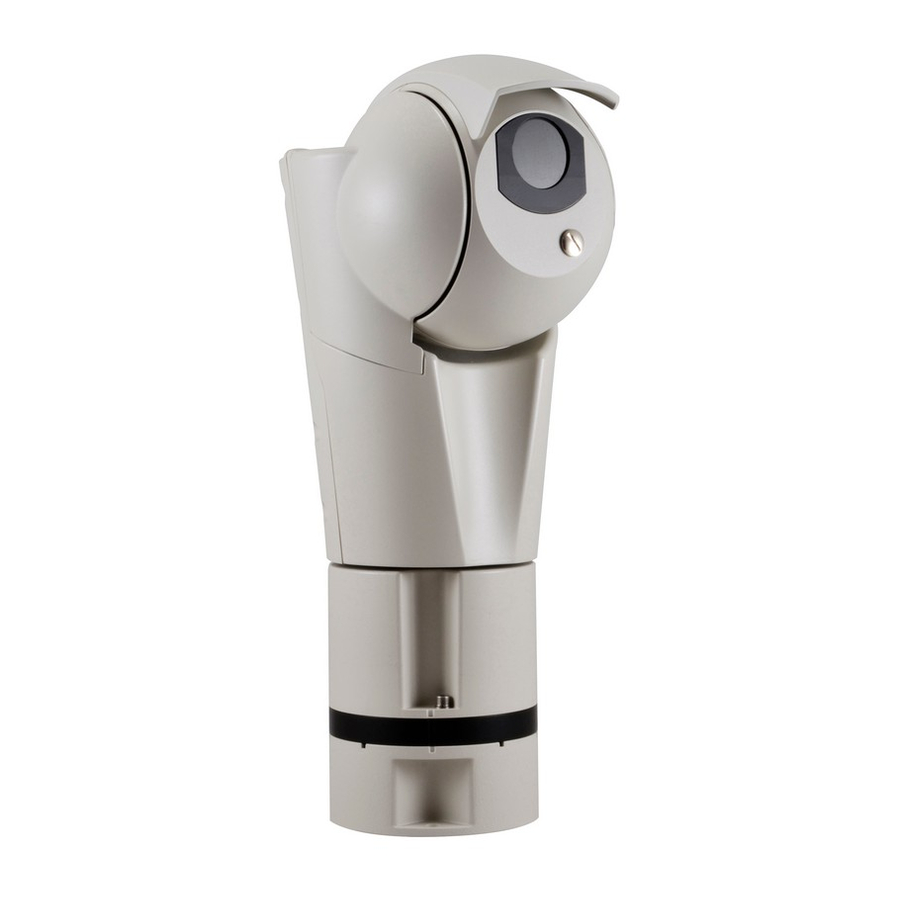
Seite 1
ITALIANO ULISSE EVO (UE), ULISSE EVO THERMAL (UET) PTZ camera with high performance and extreme reliability English - Instruction manual Italiano - Manuale di istruzioni Français - Manuel d’instructions Deutsch - Bedienungsanleitung Русский - Руководство по эксплуатации...
Seite 3
ENGLISH ULISSE EVO (UE), ULISSE EVO THERMAL (UET) PTZ camera with high performance and extreme reliability English - Instruction manual...
Contents E N G L I S H 1 About this manual ........................5 1.1 Typographical conventions ..............................5 2 Notes on copyright and information on trademarks ............. 5 3 Safety rules..........................5 4 Identification ..........................8 4.1 Product description and type designation ........................8 4.2 Product Overview...................................
Seite 6
9.2 Web interface ..................................24 9.2.1 First access to the web pages ................................24 10 Accessories and Supports ....................24 10.1 LED illuminator ...................................24 10.2 Washer....................................25 10.3 Power supply ..................................25 10.4 Wall mount bracket ................................26 10.5 Parapet bracket ...................................26 10.6 Parapet bracket with quick connectors ........................26 10.7 Corner adaptor..................................26 10.8 Pole mount adaptor ................................27 10.9 Counter-plate ..................................27...
1 About this manual 3 Safety rules Read all the documentation supplied carefully before CAUTION! Hazardous moving parts. Keep installing and using this unit. Keep the manual in a fingers and other body parts away. convenient place for future reference. CAUTION! Device installation and 1.1 Typographical conventions maintaining must be performed by...
Seite 8
• Equipment intended for installation in Restricted CAUTION! The white LED illuminator Access Location performed by specialist technical emits high intensity light. In compliance staff. with standard EN62471/IEC62471, the • Before starting any operation, make sure the photobiological safety assessment has power supply is disconnected.
Seite 9
• This is a Class A product. In a domestic • Do not use the appliance in the presence of environment this product may cause radio inflammable substances. interference. In this case the user may be required • Do not allow children or unauthorised people to to take adequate measures.
ULISSE EVO is also equipped with a wiper to ensure a clear view in any environmental conditions. An LED illuminator (850nm, 940nm or white light) is available to give visibility even in total darkness.
4.3 Product marking 5 Versions 5.1 Day/Night FULL HD 30x Super The product has a label applied in compliance with CE marking. low-light camera If the fourth character of the product code is the value "1", it means the Day/Night FULL HD 30x Super low-light camera is installed with Delux technology ( 4.3 Product marking, page 9).
6 Preparing the product for 6.2 Unpacking When the product is delivered, make sure that the package is intact and that there are no signs that it has been dropped or scratched. Any change that is not expressly approved by the manufacturer will invalidate the If there are obvious signs of damage, contact the guarantee.
6.5 Installation mode The product can be installed in various modes using the supports and various adaptors available, meeting every installation requirement. 6.5.1 Installation with internal cable passage This installation mode allows cable passage inside the mounting brackets. Fig. 1 MNVCEVO_1909_EN...
6.5.2 Installation with internal cable passage with product overturned CAUTION! Always secure the product with the safety chain (6.6.6 Fastening of the safety coupling, page 17). This installation mode allows cable passage inside the mounting brackets. In the event of installation of the product overturned, the sunshield must be assembled as illustrated in the relevant chapter (6.6.5 Sunshield mounting, page 17) and enable the Ceiling Assembly mode using the web interface.
6.5.3 Installation with quick connectors This installation mode thanks to the quick connectors allows easy and fast replacement of the unit in the event of intervention on site. Fig. 7 MNVCEVO_1909_EN...
6.5.4 Installation with quick connectors with product overturned CAUTION! Always secure the product with the safety chain (6.6.6 Fastening of the safety coupling, page 17). This installation mode thanks to the quick connectors allows easy and fast replacement of the unit in the event of intervention on site.
6.6 Preparatory work before 6.6.2 Mounting the bracket installation Take special care when attaching and fastening down the apparatus. If it is to be 6.6.1 Opening the base of the product attached to a concrete surface you must use dowel pins with a traction torque rating To avoid scratching the product with the hexagonal of at least 300dN each.
6.6.3 Cables management The cables must be adequately fastened to the structure to avoid the excessive weight causes accidental removal. You must use cables suited to the type of installation. Insert the cables into the cable glands. The M16 cable glands are suitable for cables with a diameter between 4.5mm (0.18in) and 10mm (0.39in).
6.6.4 Fixing the base to the support 6.6.6 Fastening of the safety coupling For further details on configuration and Take special care when attaching and use, refer to the manual of the relevant fastening down the apparatus. If it is to be accessory or support.
7 Installation 7.1 Connection of the connector board Never, under any circumstances, make any changes or connections that are not 7.1.1 Connector board description shown in this handbook. Failure to follow The ground cable must always be the connection instructions that are given connected to the relevant terminal (GND, in the handbook may create serious safety 7.1.1 Connector board description, page...
7.1.2 Connection of the power supply line (24Vac/24Vdc) Electrical connections must be performed with the power supply disconnected and the circuit-breaker open. When commencing installation make sure that the specifications for the power supply for the installation correspond with those required by the device.
7.1.3 Alarm and relay connections Nominal section of the cables used: consult the technical data in the relevant chapter ( 16.3 Electrical, page 30). Maximum relay voltage and current: consult the technical data in the relevant chapter (16.3 Electrical, page 30). Connect the digital I/O cable to the relative connector (J6, 7.1.1 Connector board description, page 18).
7.1.4 Connection of the Ethernet cable 7.1.4.1 PoE 90W power supply The product can be powered in PoE 90W using our Use of Ethernet cables with the following power injector (10.3 Power supply, page 25). characteristics is highly recommended: If the product is powered by two sources of power •...
7.2 Installation of the upper body Place the unit body on the base aligning the reference marks. Be especially careful not to damage internal components during installation. Installation of the upper body must take place with the base not powered. Check the LED indicated in the figure is off (Fig.
8 Switching on The automatic pre-heating (De-Ice) process could be started whenever the device is switched on and the ambient temperature is below 0°C (+32°F). The procedure is necessary to guarantee correct operation of the devices even at low temperatures. The duration ranges depending on environmental conditions (from 60 minutes to 120 minutes).
On first access, the Home page will be displayed. (white light, RAL9005). For the configuration of the web interface, please refer to the instruction manual relating to the installed firmware version, available on the product web page on www.videotec.com. MNVCEVO_1909_EN...
10.2 Washer The product can be equipped with an external pump that provides water to clean the glass. Fig. 29 UPTIRPS120UL (120Vac-24Vac). Fig. 30 OHEP90INJ, OHEP90INJUS. Fig. 27 10.3 Power supply The PTZ can be powered using the external power supply unit.
10.4 Wall mount bracket 10.6 Parapet bracket with quick connectors Wall bracket with internal cable channel. There are two quick connectors, connector RJ45 for Ethernet and a multi-polar connector for power supply and I/O. Based on the version of the support, the multi-polar connector can have 4 poles with a screw terminal or 7 poles to weld.
Special controls are implemented using the auxiliary commands of the ONVIF protocol. • Through PTZ Assistant software (the PTZ Assistant software is available to download on the product web page of our website www.videotec.com). Fig. 36 UEAP. 10.9 Counter-plate The counter-plate can be used for railing, wall or ceiling assembly, also for channel applications.
12 Maintenance • Assemble the upper body (7.2 Installation of the upper body, page 22). • Power the unit. Wait for 2 minutes. CAUTION! Device installation and maintaining must be performed by • Disconnect the power supply to the unit. specialist technical staff only.
13 Cleaning 15 Troubleshooting 13.1 Cleaning the window and Contact an authorized support centre if the problems listed below persist or you have plastic parts any other issues that are not described here. Avoid ethyl alcohol, solvents, hydrogenated hydrocarbide, strong acid and alkali. Such PROBLEM The product does not go on.
16 Technical data 16.3 Electrical Supply voltage/Current consumption: CAUTION! TNV-1 installation type. The • 24Vac ±20%, 5A, 50/60Hz installation is type TNV-1, do not connect it to SELV circuits. • 24Vdc ±10%, 5A • PoE 90W (only with OHEP90INJ or OHEP90INJO CAUTION! In order to reduce the risk of fire, accessories) only use UL Listed or CSA certified cables...
17 Technical drawings The indicated measurements are expressed in millimetres. Fig. 40 ULISSE EVO. MNVCEVO_1909_EN...
Seite 36
Fig. 41 ULISSE EVO with LED illuminator. Headquarters Italy Videotec S.p.A. France Videotec France SARL Via Friuli, 6 - I-36015 Schio (VI) - Italy Immeuble Le Montreal, 19bis Avenue du Québec, ZA de Courtaboeuf Tel. +39 0445 697411 - Fax +39 0445 697414 91140 Villebon sur Yvette - France Email: info@videotec.com...
Seite 37
ITALIANO ULISSE EVO (UE), ULISSE EVO THERMAL (UET) Telecamera PTZ con prestazioni elevate ed estrema affidabilità Italiano - Manuale di istruzioni...
Seite 39
Sommario I T A L I A N O 1 Informazioni sul presente manuale ..................5 1.1 Convenzioni tipografiche ..............................5 2 Note sul copyright e informazioni sui marchi commerciali ........... 5 3 Norme di sicurezza ........................5 4 Identificazione .......................... 8 4.1 Descrizione e designazione del prodotto ........................
Seite 40
9.2 Interfaccia web ..................................24 9.2.1 Primo accesso alle pagine web .................................24 10 Accessori e supporti ......................24 10.1 Illuminatore a LED ................................24 10.2 Impianto di lavaggio .................................25 10.3 Alimentatore ..................................25 10.4 Supporto da parete ................................26 10.5 Supporto da parapetto ..............................26 10.6 Supporto da parapetto con connettori ad innesto rapido .................26 10.7 Adattatore ad angolo ...............................26 10.8 Collare da palo ..................................27 10.9 Contropiastra ..................................27...
1 Informazioni sul presente 3 Norme di sicurezza manuale ATTENZIONE! Parti mobili pericolose. Non avvicinare dita e altre parti del corpo. Prima di installare e utilizzare questa unità, leggere attentamente tutta la documentazione fornita. Tenere ATTENZIONE! L'installazione e la il manuale a portata di mano per consultazioni manutenzione del dispositivo devono successive.
Seite 42
• L'apparecchio è destinato all'installazione in ATTENZIONE! L’illuminatore a LED a luce una Posizione ad Accesso Limitato effettuata da bianca emette luce ad alta intensità. La personale tecnico specializzato. valutazione foto-biologica di sicurezza, • Prima di eseguire qualsiasi operazione assicurarsi in accordo con la norma EN62471/ di togliere tensione al prodotto.
Seite 43
• Questo è un prodotto di Classe A. In un ambiente • Non utilizzare l’apparecchio in presenza di residenziale questo prodotto può provocare sostanze infiammabili. radiodisturbi. In questo caso può essere richiesto • Non permettere l’uso dell’apparecchio a bambini o all'utilizzatore di prendere misure adeguate.
I supporti possono essere dotati di connettori ad innesto rapido per Ethernet/PoE, ULISSE EVO è una telecamera PTZ che combina alta alimentazione e I/O, che consentono la facile e veloce tecnologia, competitività e design per garantire sostituzione dell'unità in caso di intervento in loco.
4.3 Marcatura del prodotto 5 Versioni 5.1 Telecamera Day/Night FULL Sul prodotto è applicata una etichetta conforme alla marcatura CE. HD 30x Super low-light Se nel quarto carattere del codice prodotto compare il valore "1" significa che è installata la telecamera Day/Night FULL HD 30x Super low-light con tecnologia Delux (4.3 Marcatura del prodotto, pagina 5.2 Telecamera termica...
6 Preparazione del prodotto 6.2 Disimballaggio per l'utilizzo Alla consegna del prodotto verificare che l'imballo sia integro e non presenti segni evidenti di cadute o abrasioni. Qualsiasi intervento non espressamente approvato dal costruttore fa decadere la In caso di danni evidenti all'imballo contattare garanzia.
6.5 Modalità d’installazione Il prodotto può essere installato in diversi modi utilizzando i supporti e i diversi adattatori disponibili, soddisfando ogni esigenza d’installazione. 6.5.1 Installazione con passaggio interno dei cavi Questa modalità di installazione permette il passaggio dei cavi all’interno delle staffe di supporto. Fig.
6.5.2 Installazione con passaggio interno dei cavi con prodotto capovolto ATTENZIONE! Assicurare sempre il prodotto con la catena di sicurezza (6.6.6 Fissaggio dell'aggancio di sicurezza, pagina 17). Questa modalità di installazione permette il passaggio dei cavi all'interno delle staffe di supporto. Nel caso di installazione del prodotto capovolto è...
6.5.3 Installazione con connettori a innesto rapido Questa modalità di installazione, grazie ai connettori ad innesto rapido, consente la facile e veloce sostituzione dell'unità in caso di intervento in loco. Fig. 7 MNVCEVO_1909_IT...
6.5.4 Installazione con connettori a innesto rapido con prodotto capovolto ATTENZIONE! Assicurare sempre il prodotto con la catena di sicurezza (6.6.6 Fissaggio dell'aggancio di sicurezza, pagina 17). Questa modalità di installazione, grazie ai connettori ad innesto rapido, consente la facile e veloce sostituzione dell'unità...
6.6 Lavoro preparatorio prima 6.6.2 Fissaggio del supporto dell’installazione Porre particolare attenzione ai sistemi di fissaggio dell'apparecchiatura. Se 6.6.1 Apertura della base del prodotto l'apparecchiatura deve essere fissata ad una superficie di calcestruzzo bisogna utilizzare Per evitare di graffiare il prodotto con la chiave tasselli con coppia di trazione minima esagonale, allineare il corpo del prodotto con la vite pari a 300dN cadauno.
6.6.3 Passaggio cavi I cavi devono essere opportunamente fissati alla struttura per evitare che l'eccessivo peso ne comporti lo sfilamento accidentale. I cavi utilizzati devono essere conformi al tipo di installazione. Introdurre i cavi all’interno dei pressacavi. I pressacavi M16 sono adatti per cavi con diametro compreso tra 4.5mm e 10mm.
6.6.4 Fissaggio della base al supporto 6.6.6 Fissaggio dell'aggancio di sicurezza Per ulteriori dettagli sulla configurazione e l’utilizzo fare riferimento al manuale del Porre particolare attenzione ai sistemi relativo accessorio o supporto. di fissaggio dell'apparecchiatura. Se l'apparecchiatura deve essere fissata ad una 6.6.5 Fissaggio del tettuccio superficie di calcestruzzo bisogna utilizzare È...
7 Installazione 7.1 Collegamento della scheda connettori Non effettuare per nessun motivo alterazioni o collegamenti non previsti 7.1.1 Descrizione della scheda in questo manuale. Il mancato rispetto connettori delle indicazioni fornite nel manuale in merito ai collegamenti può portare a gravi Il cavo di terra deve sempre essere collegato pericoli per la sicurezza del personale e al relativo morsetto (GND, 7.1.1 Descrizione...
7.1.2 Collegamento della linea di alimentazione (24Vac/24Vdc) Eseguire le connessioni elettriche in assenza di alimentazione e con dispositivo di sezionamento aperto. All’atto dell’installazione controllare che le caratteristiche di alimentazione fornite dall’impianto corrispondano a quelle richieste dal dispositivo. Non alimentare il prodotto mediante auto trasformatori.
7.1.3 Collegamento degli allarmi e dei relè Sezione nominale dei cavi utilizzabili: consultare i dati tecnici presenti nel relativo capitolo (16.3 Elettrico, pagina 30). Tensione e corrente massima dei relè: consultare i dati tecnici presenti nel relativo capitolo (16.3 Elettrico, pagina 30). Collegare il cavo degli I/O digitali al relativo connettore (J6, 7.1.1 Descrizione della scheda connettori, pagina 18).
7.1.4 Collegamento del cavo di rete 7.1.4.1 Alimentazione in PoE 90W Ethernet Il prodotto può essere alimentato in PoE 90W tramite il nostro power injector (10.3 Alimentatore, pagina Si raccomanda l'utilizzo di cavi Ethernet con le 25). seguenti caratteristiche: Se il prodotto viene alimentato da due fonti di •...
7.2 Installazione del corpo Posizionare il corpo dell'unità sulla base allineando le tacche di riferimento. Prestare particolare attenzione superiore a non danneggiare i componenti interni durante l'installazione. L'installazione del corpo superiore deve essere fatta con la base non alimentata. Verificare che il LED indicato in figura sia spento (Fig. 22, pagina 22).
8 Accensione La procedura di preriscaldamento automatico (De-Ice) si potrebbe attivare tutte le volte che il dispositivo viene acceso ad una temperatura ambiente inferiore a 0°C. La procedura serve a garantire la corretta funzionalità del dispositivo anche alle basse temperature. La durata varia a seconda delle condizioni climatiche (da 60 minuti fino a 120 minuti).
RAL9005). http://indirizzo_ip. Al primo accesso sarà visualizzata la pagina di Home. Per la configurazione dell'interfaccia web consultare il manuale relativo alla versione firmware installata, disponibile nella pagina web del prodotto sul nostro sito www.videotec.com. MNVCEVO_1909_IT...
10.2 Impianto di lavaggio Il prodotto può essere dotato di una pompa esterna che fornisce acqua per la pulizia del vetro. Fig. 29 UPTIRPS120UL (120Vac-24Vac). Fig. 30 OHEP90INJ, OHEP90INJUS. Fig. 27 10.3 Alimentatore Il PTZ può essere alimentato utilizzando l'alimentatore esterno. Fig.
10.4 Supporto da parete 10.6 Supporto da parapetto con connettori ad innesto rapido Supporto per montaggio a parete con passaggio interno cavi. I connettori ad innesto rapido sono due, un connettore RJ45 per l'ethernet e un connettore multipolare per alimentazione e I/O. In base alla versione del supporto il connettore multipolare può...
ONVIF. • Tramite il software PTZ Assistant (il software PTZ Assistant è disponibile per il download nella pagina web del prodotto sul nostro sito www. videotec.com). Fig. 36 UEAP. 10.9 Contropiastra La contropiastra può essere utilizzata per il montaggio a parapetto, a parete o a soffitto, anche per applicazioni con canaletta.
12 Manutenzione • Montare il corpo superiore (7.2 Installazione del corpo superiore, pagina 22). • Alimentare l'unità. Attendere 2 minuti. ATTENZIONE! L'installazione e la manutenzione del dispositivo devono • Togliere alimentazione all'unità. essere eseguite solo da personale tecnico • Aprire la base del prodotto (6.6.1 Apertura della specializzato.
13 Pulizia 15 Risoluzione dei problemi 13.1 Pulizia della finestra e delle Per qualunque problematica non descritta o se i problemi elencati di seguito parti in plastica dovessero persistere, contattare il centro di assistenza autorizzato. Evitare alcool etilico, solventi, idrocarburi idrogenati, acidi forti e alcali.
16 Dati tecnici 16.3 Elettrico Tensione di alimentazione/Corrente assorbita: ATTENZIONE! L'installazione è di tipo TNV-1. • 24Vac ±20%, 5A, 50/60Hz Non collegare a circuiti SELV. • 24Vdc ±10%, 5A ATTENZIONE! Per ridurre il rischio di • PoE 90W (solo con l'accessorio OHEP90INJ o incendio usare solamente cavi certificati OHEP90INJO) UL Listed o CSA aventi sezioni maggiori o...
16.5 Video 16.6 Telecamere Encoder video Day/Night Full HD 30x • Protocollo di comunicazione: ONVIF, Profilo S e Risoluzione: Full HD 1080p (1920x1080) Profilo Q Sensore di immagine: 1/2.8" Exmor™ R CMOS sensor • Configurazione del dispositivo: TCP/IPv4-IPv6, Pixel Effettivi: appross. 2.38 Megapixel UDP/IPv4-IPv6, HTTP, HTTPS, NTP, DHCP, WS- Illuminazione Minima: DISCOVERY, DSCP, IGMP (Multicast), SOAP, DNS...
17 Disegni tecnici Le misure indicate sono espresse in millimetri. Fig. 40 ULISSE EVO. MNVCEVO_1909_IT...
Seite 70
Fig. 41 ULISSE EVO con illuminatore a LED. Headquarters Italy Videotec S.p.A. France Videotec France SARL Via Friuli, 6 - I-36015 Schio (VI) - Italy Immeuble Le Montreal, 19bis Avenue du Québec, ZA de Courtaboeuf Tel. +39 0445 697411 - Fax +39 0445 697414 91140 Villebon sur Yvette - France Email: info@videotec.com...
Seite 71
FRANÇAIS ULISSE EVO (UE), ULISSE EVO THERMAL (UET) Caméra PTZ haute performance et fiabilité extrême Français - Manuel d’instructions...
Seite 73
Sommaire F R A N Ç A I S 1 À propos de ce mode d’emploi ....................5 1.1 Conventions typographiques ............................5 2 Notes sur le copyright et informations sur les marques de commerce ........ 5 3 Normes de securité ........................5 4 Identification ..........................
Seite 74
9.2 Interface web ..................................24 9.2.1 Premier accès aux pages web ................................24 10 Accessoires et supports......................24 10.1 Projecteur à LED .................................24 10.2 Système de lavage ................................25 10.3 Alimentation ..................................25 10.4 Support fixation murale ..............................26 10.5 Support fixation sol ................................26 10.6 Support de parapet avec connecteurs à fixation rapide ..................26 10.7 Adaptateur d'angle ................................26 10.8 Collier de fixation sur poteau ............................27 10.9 Contre-plaque ..................................27...
1 À propos de ce mode 3 Normes de securité d’emploi ATTENTION! Parties mobiles dangereux. Ne pas approcher les doigts ou d'autres parties Avant d'installer et d'utiliser cette unité, lire du corps. attentivement toute la documentation fournie. Garder le manuel à portée de main pour des ATTENTION! L’installation et l’entretien consultations successives.
Seite 76
• Les matériels sont destinés à être installés dans des ATTENTION! Le projecteur à LED à EMPLACEMENTS À ACCÈS RESTREINT. lumière blanche émet une lumière à forte • Sectionner l'alimentation avant de procéder à intensité. L'évaluation photo-biologique toute opération. de sécurité, conformément à la norme •...
Seite 77
• Ce produit appartient à la Classe A. Dans un • Ne pas utiliser l'appareil en présence de substances milieu résidentiel ce produit peut être la cause de inflammables. radioperturbations. Dans ce cas il est préferable de • Ne pas laisser l'appareil à portée des enfants ou de prendre des mésures appropritées.
Les supports peuvent être équipés de connecteurs à fixation rapide pour ULISSE EVO est une caméra PTZ qui allie technologie, Ethernet/PoE, alimentation et I/O, qui permettent de compétitivité et design pour garantir une sécurité remplacer facilement et rapidement l’unité en cas optimale de la vidéo-surveillance des centres urbains,...
4.3 Marquage du produit 5 Versions 5.1 Caméra Jour/Nuit FULL HD Une étiquette conforme au marquage CE est apposée sur le produit. 30x Super low-light Si le quatrième caractère du code du produit affiche la valeur « 1 », ceci signifie que la caméra Jour/Nuit FULL HD 30x Super low-light avec la technologie Delux est installée (4.3 Marquage du produit, page 9).
6 Préparation du produit en 6.2 Déballage vue de l’utilisation Lors de la livraison du produit, vérifier que l’emballage est en bon état et l’absence de tout signe évident de chute ou d’abrasion. Toute modification non approuvée expressément par le fabricant entraînera En cas de dommages évidents, contacter l’annulation de la garantie.
6.5 Modes d’installation Le produit peut être installé de plusieurs façons avec les différents supports et adaptateurs disponibles, pour répondre à chaque exigence d’installation. 6.5.1 Installation avec passage de câble interne Ce mode d’installation permet le passage des câbles à l’intérieur des brides de support. Fig.
6.5.2 Installation avec passage interne des câbles avec le produit inversé ATTENTION! Sécurisez toujours le produit avec la chaîne de sécurité (6.6.6 Fixation d’accrochage de sécurité, page 17). Ce mode d'installation permet le passage des câbles à l'intérieur des brides de support. En cas d'installation du produit inversé, vous devez installer le toit pare-soleil comme indiqué...
6.5.3 Installation avec des connecteurs à fixation rapide Ce mode d'installation, grâce aux connecteurs à fixation rapide, permet de remplacer facilement et rapidement l'unité en cas d'intervention sur site. Fig. 7 MNVCEVO_1909_FR...
6.5.4 Installation avec connecteurs rapide avec produit inversé ATTENTION! Sécurisez toujours le produit avec la chaîne de sécurité (6.6.6 Fixation d’accrochage de sécurité, page 17). Ce mode d'installation, grâce aux connecteurs à fixation rapide, permet de remplacer facilement et rapidement l'unité...
6.6 Opérations à effectuer avant 6.6.2 Fixation du support l’installation Accorder une attention particulière aux systèmes de fixation de l'appareil. 6.6.1 Ouverture de la base du produit Si l'appareil doit être fixé à une surface en béton, utiliser des chevilles avec un Pour éviter de rayer le produit avec la clé...
6.6.3 Passage des câbles Les câbles doivent être adéquatement fixés à la structure afin d'éviter que le poids excessif provoque son extraction accidentelle. Les câbles utilisés doivent être conformes au type d'installation. Insérez les câbles dans les presse-étoupes. Les presse-étoupes M16 sont adaptés pour des câbles ayant un diamètre compris entre 4.5mm et 10mm.
6.6.4 Fixage de la base au support 6.6.6 Fixation d’accrochage de sécurité Pour plus d'informations sur la Accorder une attention particulière configuration et l'utilisation, reportez-vous aux systèmes de fixation de l'appareil. au manuel de l'accessoire ou du support Si l'appareil doit être fixé à une surface concerné.
7 Installation 7.1 Connexion de la carte de connexion Ne procéder sous aucun prétexte à des modifications ou des connexions non 7.1.1 Description de la carte de prévues dans ce manuel. L’utilisation connexion d’appareils inadéquats peut comporter des risques sérieux pour les appareils et la Le câble de terre doit toujours être branché...
7.1.2 Connexion de la ligne d'alimentation (24Vac/24Vdc) Il faut effectuer les connexions électriques en absence d'alimentation et lorsque le dispositif de sectionnement ouvert. Contrôler que les sources d'alimentation et les câbles de branchement sont en mesure de supporter la consommation du système. N'alimentez pas le produit avec des autotransformateurs.
7.1.3 Branchement aux alarmes et aux relais Section nominale des câbles utilisés: consultez les caractéristiques techniques figurant au chapitre correspondant (16.3 Électrique, page 30). Tension et courant maximum de relais: consultez les caractéristiques techniques figurant au chapitre correspondant (16.3 Électrique, page 30). Branchez le câble des entrées/sorties numériques au RL2B connecteur correspondant (J6, 7.1.1 Description de la...
7.1.4 Branchement du câble de réseau 7.1.4.1 Alimentation en PoE 90W Ethernet Le produit peut être alimenté en PoE 90W via notre injecteur de puissance (10.3 Alimentation, page 25). Nous recommandons l'utilisation de câbles Ethernet Si le produit est alimenté par deux sources d'énergie ayant les caractéristiques suivantes: en même temps (24V et PoE 90W), seule la ligne en •...
7.2 Installation du haut du corps Placez le corps de l’appareil sur la base en alignant les encoches de référence. Veillez à ne pas abîmer les composants intérieurs lors de l’installation. La partie supérieure du corps doit être installée quand la base n'est pas alimentée. Vérifiez que la LED indiqué...
8 Allumage La procédure de préchauffage automatique (De-Ice) peut être activée chaque fois que le dispositif est mis en fonction à une température ambiante inférieure à 0°C. La procédure permet de garantir un fonctionnement correct du dispositif également à basse température. La durée varie en fonction des conditions climatiques (de 60 minutes jusqu'à...
(lumière blanche, RAL9005). La page d'accueil sera affichée au premier accès. Pour la configuration de l'interface web, veuillez vous reporter au manuel d’instruction relatif à la version du firmware installé, disponible sur la page web du produit sur www.videotec.com. MNVCEVO_1909_FR...
10.2 Système de lavage Le produit peut être équipé d'une pompe externe qui fournit l'eau pour nettoyer la vitre. Fig. 29 UPTIRPS120UL (120Vac-24Vac). Fig. 30 OHEP90INJ, OHEP90INJUS. Fig. 27 10.3 Alimentation Le PTZ peut être alimenté par l'alimentation externe. Fig. 31 OHEP90INJO.
10.4 Support fixation murale 10.6 Support de parapet avec connecteurs à fixation rapide Support mural avec passage interne des câbles. Il y a deux connecteurs à fixation rapide, un connecteur RJ45 pour Ethernet et un connecteur multipolaire pour l'alimentation et les I/O. Selon la version du support, le connecteur multipolaire peut être à...
Commandes spéciales sont implémentées à l'aide des commandes auxiliaires du protocole ONVIF. • À l'aide du logiciel PTZ Assistant (le logiciel PTZ Assistant peut être téléchargé librement sur la page web du produit, sur notre site www.videotec. com). Fig. 36 UEAP.
12 Entretien • Monter le haut du corps (7.2 Installation du haut du corps, page 22). • Allumer l'unité. Attendre 2 minutes. ATTENTION! L’installation et l’entretien du dispositif doivent être effectués • Couper l'alimentation à l'unité. exclusivement par un personnel technique •...
13 Nettoyage 15 Dépannage 13.1 Nettoyage de la fenêtre et Pour toute problématique que ce soit non décrite ou si les problèmes énumérés des parties en plastique ci-après persistent, contacter le centre d'assistance autorisé. On doit éviter alcool éthylique, solvants, hydrocarbures hydro-génés, acides forts PROBLÈME Le produit ne s'allume pas.
16 Données techniques 16.3 Électrique Tension d’alimentation/Courant absorbé: ATTENTION! L'installation est du type TNV- • 24Vac ±20%, 5A, 50/60Hz 1. Ne pas la connecter à des circuits SELV. • 24Vdc ±10%, 5A ATTENTION! Pour réduire les risques • PoE 90W (uniquement avec l'accessoire d’incendie, utiliser uniquement des câbles OHEP90INJ ou OHEP90INJO) certifiés UL Listed ou CSA de sections égales...
17 Dessins techniques Les tailles indiquées sont en millimètres. Fig. 40 ULISSE EVO. MNVCEVO_1909_FR...
Seite 104
Fig. 41 ULISSE EVO avec projecteur à LED. Headquarters Italy Videotec S.p.A. France Videotec France SARL Via Friuli, 6 - I-36015 Schio (VI) - Italy Immeuble Le Montreal, 19bis Avenue du Québec, ZA de Courtaboeuf Tel. +39 0445 697411 - Fax +39 0445 697414 91140 Villebon sur Yvette - France Email: info@videotec.com...
Seite 105
DEUTSCH ULISSE EVO (UE), ULISSE EVO THERMAL (UET) PTZ-Kamera mit ausgezeichneten Leistungen und äußerster Zuverlässigkeit Deutsch - Bedienungsanleitung...
Seite 107
Inhaltsverzeichnis D E U T S C H 1 Allgemeines ..........................5 1.1 Schreibweisen..................................5 2 Anmerkungen zum Copyright und Informationen zu den Handelsmarken ......5 3 Sicherheitsnormen ........................5 4 Identifizierung .......................... 8 4.1 Beschreibung und Bezeichnung des Produktes ......................8 4.2 Produktübersicht ..................................
Seite 108
9.2 Web-Schnittstelle .................................24 9.2.1 Erster Webseitenaufruf ..................................24 10 Zubehör und Support ......................24 10.1 LED- Scheinwerfer ................................24 10.2 Waschanlage ..................................25 10.3 Netzteil ....................................25 10.4 Wandhalterung ...................................26 10.5 Halterung für Brüstungsmontage..........................26 10.6 Geländerhalterung mit Steckverbindern mit Schnellkupplung ...............26 10.7 Winkeladapter ..................................26 10.8 Massive Mastschelle ................................27 10.9 Gegenplatte ..................................27 11 Anleitung für den normalen Betrieb ..................27 12 Wartung ..........................28...
1 Allgemeines 3 Sicherheitsnormen Vor Installation und Anwendung der Einheit ist die ACHTUNG! Gefährliche Losteile. Finger und gesamte gelieferte Dokumentation aufmerksam zu andere Körperteile fernhalten. lesen. Zum späteren Nachschlagen das Handbuch in Reichweite aufbewahren. ACHTUNG! Die Installation und Wartung der Vorrichtung ist technischen Fachleuten 1.1 Schreibweisen vorbehalten.
Seite 110
• Das Gerät muss von technischen Fachleuten ACHTUNG! Der LED-Scheinwerfer mit vorbehalten an einem Ort mit beschränktem weißem Licht erzeugt Licht mit hoher Zugriff installiert werden. Intensität. Aufgrund der Bewertung • Unterbrechen Sie die Stromversorgung, bevor die der photobiologischen Sicherheit, in beschriebenen Arbeiten durchgeführt werden.
Seite 111
• Dies ist ein Produkt der Klasse A. Dieses Produkt • Das Gerät nicht in der Nähe entzündlicher Stoffe kann im Wohnbereich Funkstörungen verursachen. benutzen. In diesem Fall kann vom Betreiber verlangt werden, • Kindern oder unbefugten Personen ist der angemessene Maßnahmen durchzuführen.
Halterungen und Adapter Bezeichnung des Produktes verwendet, um allen Installationsanforderungen nachzukommen. Die Halterungen können mit ULISSE EVO ist eine PTZ-Kamera, die Hightech, Steckverbindern mit Schnellkupplung für Ethernet/ Wettbewerbsfähigkeit und Design auf sich vereint, PoE, Versorgung und I/O ausgestattet werden, die um äußerste Sicherheit bei der Videoüberwachung...
4.3 Kennzeichnung des Produkts 5 Versionen 5.1 Tag- und Nachtkamera FULL Auf dem Produkt befindet sich ein Etikett, das mit der CE-Kennzeichnung HD 30x Super low-light übereinstimmt. Sollte das vierte Zeichen des Produktcodes mit dem Wert „1“ erscheinen, bedeutet das, dass die Tag- und Nachtkamera FULL HD 30x Super low-light mit Delux- Technologie installiert ist (4.3 Kennzeichnung des Produkts, Seite 9).
6 Vorbereitung des 6.2 Entfernen der Verpackung Produktes auf den Gebrauch Bei der Lieferung des Produktes ist zu prüfen, ob die Verpackung intakt ist oder offensichtliche Anzeichen von Stürzen oder Abrieb aufweist. Jede vom Hersteller nicht ausdrücklich genehmigte Veränderung führt zum Verfall Bei offensichtlichen Schadensspuren an der der Gewährleistungsrechte.
6.5 Art der Installation Das Produkt kann auf verschiedene Arten installiert werden. Hierzu die Halterungen und die verschiedenen, zur Verfügung stehenden Adapter verwenden, um jeder Installationsanforderung nachzukommen. 6.5.1 Installation mit innenlaufender Kabelführung Diese Art der Installation ermöglicht die innenlaufende Kabelführung der Bügelhalterung. Abb.
6.5.2 Installation mit innenlaufender Kabelführung mit umgekehrtem Produkt ACHTUNG! Das Produkt immer mit der Sicherheitskette sichern (6.6.6 Befestigung des Sicherheitshaken, Seite 17). Diese Art der Installation ermöglicht die innenlaufende Kabelführung der Bügelhalterung. Bei umgekehrter Produktinstallation ist das Sonnenschutzdach zu montieren. Dies ist abgebildet im zugehörigen Kapitel (6.6.5 Befestigung des Dachs, Seite 17) und über die Webschnittstelle ist der Modus Deckenmontage zu aktivieren.
6.5.3 Installation mit Steckverbindern mit Schnellkupplung Diese Installationsart ermöglicht durch die Steckverbinder mit Schnellkupplung den einfachen und schnellen Austausch der Einheit bei Arbeiten vor Ort. Abb. 7 MNVCEVO_1909_DE...
6.5.4 Installation mit Steckverbindern mit Schnellkupplung bei umgekehrtem Produkt ACHTUNG! Das Produkt immer mit der Sicherheitskette sichern (6.6.6 Befestigung des Sicherheitshaken, Seite 17). Diese Installationsart ermöglicht durch die Steckverbinder mit Schnellkupplung den einfachen und schnellen Austausch der Einheit bei Arbeiten vor Ort. Bei umgekehrter Produktinstallation ist das Sonnenschutzdach zu montieren.
6.6 Auf die Installation 6.6.2 Befestigung der Halterung vorbereitende Tätigkeiten Besondere Aufmerksamkeit verlangen die Befestigungssysteme des Gerätes. 6.6.1 Öffnen der Basis des Produkts Soll das Gerät an einer Betonfläche fixiert werden, müssen Dübel verwendet werden, Um das Produkt mit dem Sechskantschlüssel nicht deren Zugmoment jeweils mindestens zu verkratzen, den Korpus des Produkts mit der zu 300dN beträgt.
6.6.3 Kabelführung Die Kabel müssen passend an der Struktur befestigt werden, um zu vermeiden, dass ein übermäßiges Gewicht zu einem versehentlichen Herabgleiten führt. Die verwendeten Kabel müssen der Anlagenart angemessen sein. Führen Sie die Kabel in die Kabelverschraubungen ein. Die Kabeldurchführungen M16 sind für Kabel mit einem Durchmesser von 4.5mm bis 10mm geeignet.
6.6.4 Befestigung der Basis an der 6.6.6 Befestigung des Sicherheitshaken Halterung Besondere Aufmerksamkeit verlangen die Befestigungssysteme des Gerätes. Für nähere Einzelheiten bzgl. der Soll das Gerät an einer Betonfläche fixiert Konfiguration und Anwendung auf das werden, müssen Dübel verwendet werden, Handbuch des entsprechenden Zubehörs deren Zugmoment jeweils mindestens oder der entsprechenden Halterung Bezug...
7 Installation 7.1 Anschluss der Verbinderplatine Unter keinen Umständen dürfen Veränderungen oder Anschlüsse 7.1.1 Beschreibung der Karte vorgenommen werden, die in diesem Anschlüsse Handbuch nicht genannt sind. Die Missachtung der Angaben, die das Das Erdungskabel muss immer an der Handbuch zu den Anschlüssen macht, entsprechenden Klemme angeschlossen kann die Sicherheit von Personen und die sein (GND, 7.1.1 Beschreibung der Karte...
7.1.2 Anschluss der Stromversorgung (24Vac/24Vdc) Die elektrischen Anschlüsse nur durchführen, wenn die Stromversorgung abgetrennt und die Trennvorrichtung offen ist. Im Zuge der Installation ist zu prüfen, ob die Merkmale der von der Anlage bereitgestellten Versorgung mit den erforderlichen Merkmalen der Einrichtung übereinstimmen.
7.1.3 Anschluss an Alarme und Relais Nennquerschnitt der verwendeten Kabel: die technischen Daten im entsprechenden Kapitel einsehen (16.3 Elektrik, Seite 30). Höchstspannung und -strom der Relais: die technischen Daten im entsprechenden Kapitel einsehen (16.3 Elektrik, Seite 30). Das Kabel der digitalen E/A mit dem entsprechenden Steckanschluss verbinden (J6, 7.1.1 Beschreibung der Karte Anschlüsse, Seite 18).
7.1.4 Anschluss des Ethernet-Kabels 7.1.4.1 PoE 90W Versorgung Das Produkt kann mit PoE 90W durch unseren Power Empfohlen wird die Verwendung von Ethernetkabeln Injector versorgt werden (10.3 Netzteil, Seite 25). mit den folgenden Eigenschaften: Wenn das Produkt von zwei Versorgungsquellen (24V •...
7.2 Installation des oberen Den Korpus der Einheit auf der Basis positionieren. Hierzu die Bezugskerben angleichen. Genau darauf Korpus achten, die internen Komponenten während der Installation nicht zu beschädigen. Die Installation des oberen Korpus ist bei nicht spannungsführender Basis durchzuführen. Überprüfen, dass die in der Abbildung gezeigte LED aus ist (Abb.
8 Einschaltung Der automatische Vorheizvorgang (De-Ice) könnte immer dann aktiviert werden, wenn das Gerät bei einer Umgebungstemperatur von unter 0°C in Betrieb genommen wird. Dieser Vorgang ist notwendig, um die korrekte Funktionalität der Vorrichtung auch bei niedrigen Temperaturen zu gewährleisten. Die Dauer liegt je nach Wetterbedingungen (von 60 Minuten bis zu 120 Minuten).
RAL9005)/UEIWAA (weißes Licht, RAL9002)/UEIWFA herzustellen. (weißes Licht, RAL9005). Beim ersten Zugriff wird die Startseite angezeigt. Informationen zur Konfiguration der Webschnittstelle finden Sie im Handbuch, das sich auf die installierte Firmware-Version bezieht. Das Handbuch ist auf der Produktwebseite in www.videotec.com verfügbar. MNVCEVO_1909_DE...
10.2 Waschanlage Das Produkt kann mit einer externen Pumpe ausgestattet werden, die Wasser für die Reinigung des Glases liefert. Abb. 29 UPTIRPS120UL (120Vac-24Vac). Abb. 30 OHEP90INJ, OHEP90INJUS. Abb. 27 10.3 Netzteil Die Stromversorgung der PTZ-Einheit kann durch Verwendung eines externen Netzteils erfolgen. Abb.
10.4 Wandhalterung 10.6 Geländerhalterung mit Steckverbindern mit Wandhalterung mit interner Kabelführung. Schnellkupplung Es gibt zwei Steckverbinder mit Schnellkupplung. Einen Steckverbinder RJ45 für Ethernet und einen mehradrigen Steckverbinder für die Versorgung und I/O. Basierend auf der Version der Halterung kann der mehradrige Steckverbinder 4 Pole mit Schraubklemme oder 7 zu schweißende Pole haben.
Sonderbefehle mittels der Hilfsbefehle des ONFIV-Protokolls implementiert. • Über die Software PTZ Assistant (die Software PTZ Assistant kann auf der Webseite des Produkts auf unserer Website www.videotec.com heruntergeladen werden). Abb. 36 UEAP. 10.9 Gegenplatte Die Gegenplatte kann für die Geländer-, Wand- oder Deckenmontage verwendet werden, auch für...
12 Wartung • Den oberen Korpus montieren (7.2 Installation des oberen Korpus, Seite 22). • Die Einheit mit Strom versorgen. 2 Minuten warten. ACHTUNG! Die Installation und Wartung der Vorrichtung ist technischen Fachleuten • Die Stromversorgung der Einheit trennen. vorbehalten. •...
13 Reinigung 15 Problemlösung 13.1 Reinigung des Fensters und Kontaktieren Sie bitte das autorisierte Kundenzentrum bei jedem nicht der Kunststoffteile beschriebenen Problem oder falls das aufgelistete Problem weiterhin bestehen Zu vermeiden sind Äthylalkohol, sollte. Lösungsmittel, hydrierte Kohlenwasserstoffe, starke Säuren und PROBLEM Das Produkt lässt sich nicht alkalische Lösungen.
16 Technische Daten 16.3 Elektrik Versorgungsspannung/Stromaufnahme: ACHTUNG! Die Anlage gehört zum Typ TNV- • 24Vac ±20%, 5A, 50/60Hz 1. Nicht an Kreisläufe SELV anschließen. • 24Vdc ±10%, 5A ACHTUNG! Zur Senkung der Brandgefahr • PoE 90W (nur mit dem Zubehör OHEP90INJ oder dürfen nur UL Listed oder CSA zertifizierte OHEP90INJO) Kabel benutzt werden, die mindestens...
17 Technische Zeichnungen Die Maße sind in Millimetern angegeben. Abb. 40 ULISSE EVO. MNVCEVO_1909_DE...
Seite 138
Abb. 41 ULISSE EVO mit LED Scheinwerfer. Headquarters Italy Videotec S.p.A. France Videotec France SARL Via Friuli, 6 - I-36015 Schio (VI) - Italy Immeuble Le Montreal, 19bis Avenue du Québec, ZA de Courtaboeuf Tel. +39 0445 697411 - Fax +39 0445 697414 91140 Villebon sur Yvette - France Email: info@videotec.com...
Seite 139
РУССКИЙ ULISSE EVO (UE), ULISSE EVO THERMAL (UET) PTZ-камера с высокой производительностью и чрезвычайной надежностью Русский - Руководство по эксплуатации...
Seite 141
Комплект оборудования Р У С С К И Й 1 О настоящем руководстве ..................... 5 1.1 Типографские условные обозначения ........................5 2 Примечания в отношении авторского права и информация о торговых марках..5 3 Правила техники безопасности ................... 5 4 Обозначение ..........................8 4.1 Описание...
Seite 142
9.2 Веб-интерфейс ..................................24 9.2.1 Первый вход на веб-страницу ...............................24 10 Принадлежности и опоры ....................24 10.1 Светодиодный осветитель ............................24 10.2 Омыватель (Washer) ................................25 10.3 Источник питания ................................25 10.4 Кронштейн для крепления на стене ........................26 10.5 Кронштейн для крепления параллельно потолку ....................26 10.6 Поддерживает...
1 О настоящем руководстве 3 Правила техники безопасности Внимательно ознакомьтесь со всей документацией, входящей в комплект поставки, перед тем как приступить к установке и эксплуатации данного ПРЕДУПРЕЖДЕНИЕ! Опасные оборудования. Всегда держите руководство под движущиеся детали. Следите за тем, рукой, чтобы им можно было воспользоваться в чтобы...
Seite 144
• Установка оборудования, предназначенного ПРЕДУПРЕЖДЕНИЕ! Светодиодный для использования в зонах с ограниченным прожектор белого света излучает доступом, должна осуществляться только высокоинтенсивный луч света. квалифицированным техническим персоналом. В соответствии с оценкой • Перед тем, как приступить к выполнению фотобиологической безопасности в любых...
Seite 145
• Это устройство Класса А. При установке • Не используйте оборудование вблизи в жилых помещениях данное устройство воспламеняющихся веществ. может вызывать радиопомехи. В таком • Не разрешайте детям или неуполномоченным случае пользователю может потребоваться лицам использовать оборудование. предпринять соответствующие меры. •...
с помощью большого ассортимента типа устройства кронштейнов и адаптеров для любых условий установки. Кронштейны могут быть также PTZ-камера ULISSE EVO сочетает в себе передовые оснащены разъемами для быстрого подключения технологии, конкурентные преимущества и дизайн к Ethernet/PoE, источнику питания и I/O, что...
4.3 Маркировка изделия 5 Модели 5.1 Камера Day/Night FULL HD На устройстве размещается этикетка в соответствии с маркировкой CE. 30x для работы в условиях крайне слабого освещения Если на месте четвертого символа кода изделия стоит "1", значит, установлена камера Day/Night FULL HD 30x для...
6 Подготовка устройства к 6.2 Распаковка использованию При получении устройства убедитесь, что упаковка не повреждена и не имеет явных признаков падения или царапин. Любое изменение, которое выполняется без разрешения, явным образом В случае наличия видимых повреждений предоставленного производителем, незамедлительно свяжитесь с поставщиком. аннулирует...
6.5 Способ установки Устройство можно установить различными способами благодаря большому выбору кронштейнов и адаптеров, позволяющих учитывать любые условия установки. 6.5.1 Установка с внутренней прокладкой кабелей Такой способ установки позволяет прокладывать кабели внутри монтажных кронштейнов. Рис. 1 MNVCEVO_1909_RU...
6.5.2 Установка с внутренней прокладкой кабелей и размещением устройства в перевернутом положении ПРЕДУПРЕЖДЕНИЕ! Всегда закрепляйте устройство с помощью крепежной цепи (6.6.6 Установка предохранительной муфты, страница 17). Такой способ установки позволяет прокладывать кабели внутри монтажных кронштейнов. При установке устройства в перевернутом положении необходимо установить солнцезащитный козырек, как...
6.5.3 Установка с разъемами для быстрого подключения Благодаря разъемам для быстрого подключения данный способ установки обеспечивает простую и быструю замену устройства в случае проведения работ прямо на месте. Рис. 7 MNVCEVO_1909_RU...
6.5.4 Установка с разъемами для быстрого подключения устройства в перевернутом положении ПРЕДУПРЕЖДЕНИЕ! Всегда закрепляйте устройство с помощью крепежной цепи (6.6.6 Установка предохранительной муфты, страница 17). Благодаря разъемам для быстрого подключения данный способ установки обеспечивает простую и быструю замену устройства в случае проведения работ прямо на месте. При...
6.6 Подготовительные работы 6.6.2 Установка кронштейна перед установкой Особое внимание обратите на размещение и крепление оборудования. 6.6.1 Открытие основания устройства Если его необходимо закрепить на бетонной поверхности, следует Чтобы не поцарапать изделие шестигранным использовать установочные штифты ключом, выровняйте корпус относительно винта, с...
6.6.3 Кабельная укладка Кабели должны быть надлежащим образом закреплены на устройстве во избежание образования чрезмерного веса, который может привести к случайному разъединению. Необходимо использовать подходящие к типу установки кабели. Вставьте кабели в кабельные муфты. Кабельные вводы M16 подходят для кабелей диаметром...
6.6.4 Крепление основания к опорной 6.6.6 Установка предохранительной конструкции муфты Более подробная информация о Особое внимание обратите на размещение конфигурации и способах использования и крепление оборудования. Если его представлена в руководстве для необходимо закрепить на бетонной соответствующего комплектующего поверхности, следует использовать оборудования...
7 Монтаж 7.1 Подключение платы разъемов Никогда и ни при каких обстоятельствах не выполняйте изменений или 7.1.1 Описание платы разъемов подключений, не предусмотренных Кабель заземления должен быть всегда настоящим руководством. Несоблюдение подключен к соответствующей клемме изложенных в руководстве инструкций (GND, 7.1.1 Описание платы разъемов, по...
7.1.2 Подключение линии питания (24Vac/24Vdc) Выполнять электрические подключения необходимо при отключенном источнике питания и разомкнутом выключателе сети. Перед началом монтажа убедитесь в том, что характеристики источника питания соответствуют характеристикам устройства. Не следует подключать питание к устройству с помощью автотрансформаторов. Проверьте соответствие размеров гнезда питания...
7.1.3 Подключение аварийных сигналов и реле Номинальное сечение используемых кабелей: технические данные приведены в соответствующей главе (16.3 Электрические хар., страница 30). Напряжение и максимальный ток реле: технические данные приведены в соответствующей главе (16.3 Электрические хар., страница 30). Подключите кабель цифровых входов/выходов RL2B к...
7.1.4 Подключение Ethernet-кабеля 7.1.4.1 Питание PoE 90W Устройство может питаться от PoE 90W через Настоятельно рекомендуется использовать наш инжектор питания (10.3 Источник питания, Ethernet-кабели со следующими страница 25). характеристиками: Если изделие получает питание одновременно • Категория 5E (или выше) от двух источников (24V и PoE 90W), то •...
7.2 Установка верхней части Установите корпус устройства на основание, совместив установочные метки. Будьте особенно корпуса внимательны, чтобы во время установки не повредить внутренние компоненты. При установке верхней части корпуса необходимо отключить питание основания. Убедитесь, что указанный на рисунке светодиод не горит...
8 Включение Процесс автоматического предварительного подогрева (De-Ice) активируется при каждом включении устройства, если температура окружающей среды ниже 0°C. Данный процесс служит для обеспечения правильного функционирования устройства даже при низких температурах. Продолжительность процесса зависит от условий окружающей среды (от 60 минут до 120 минут).
UEI8AA (850nm, RAL9002)/UEI8FA (850nm, RAL9005)/UEI9AA (940nm, RAL9002)/UEI9FA (940nm, http:/ip_address. RAL9005)/UEIWAA (белый свет, RAL9002)/UEIWFA При первом входе будет отображаться Главная (белый свет, RAL9005). страница. Информацию о настройке веб-интерфейса см. в руководстве, относящемуся к установленной версии прошивки, которое доступно на нашем веб-сайте www.videotec.com. MNVCEVO_1909_RU...
10.2 Омыватель (Washer) Изделие может быть оснащено внешним насосом подачи воды для очистки стекла. Рис. 29 UPTIRPS120UL (120Vac-24Vac). Рис. 30 OHEP90INJ, OHEP90INJUS. Рис. 27 10.3 Источник питания Поворотное устройство может получать питание от внешнего источника питания. Рис. 31 OHEP90INJO. Рис. 28 UPTIRPS100N (100Vac-24Vac), UPTIRPS230N (230Vac- 24Vac).
10.4 Кронштейн для крепления 10.6 Поддерживает установку на на стене парапеты, имеет удобные разъемы для быстрого подключения Настенный кронштейн с внутренним кабельным каналом. Имеется два быстроразъемных соединения: разъем RJ45 для кабеля ethernet и разъем для многожильного кабеля питания и ввода / вывода. В...
включаются с помощью вспомогательных команд протокола ONVIF. • Через программное обеспечение PTZ Assistant (программное обеспечение PTZ Assistant доступно для загрузки с веб-страницы с данным устройством на нашем сайте www.videotec.com). Рис. 36 UEAP. 10.9 Пластина крепления Пластину крепления можно использовать для...
12 Техническое • Установите верхнюю часть корпуса (7.2 Установка верхней части корпуса, страница 22). обслуживание • Подключите устройство к сети электропитания. Подождите 2 минуты. ПРЕДУПРЕЖДЕНИЕ! Установка • Отключите питание устройства. и обслуживание устройства • Откройте основание устройства (6.6.1 Открытие должны осуществляться только основания...
13 Очистка 15 Поиск и устранение неисправностей 13.1 Чистка окна и пластмассовых деталей В том случае, если перечисленные ниже проблемы не удается устранить Не используйте этиловый спирт, или если вы столкнулись с другими растворители, галогенированные проблемами, описание которых углеводороды, сильные кислоты и здесь...
16 Технические 16.3 Электрические хар. характеристики Напряжение сети питания/Потребляемый ток: • 24Vac ±20%, 5A, 50/60Hz ПРЕДУПРЕЖДЕНИЕ! Система типа НТС-1 • 24Vdc ±10%, 5A Это система типа НТС-1, не подключайте • PoE 90W (только с принадлежностью OHEP90INJ ее к СНБН-схемам. или OHEP90INJO) Функция...
17 Технические чертежи Размеры указаны в миллиметрах. Рис. 40 ULISSE EVO. MNVCEVO_1909_RU...
Seite 172
Рис. 41 ULISSE EVO со светодиодным осветителем. Headquarters Italy Videotec S.p.A. France Videotec France SARL Via Friuli, 6 - I-36015 Schio (VI) - Italy Immeuble Le Montreal, 19bis Avenue du Québec, ZA de Courtaboeuf Tel. +39 0445 697411 - Fax +39 0445 697414 91140 Villebon sur Yvette - France Email: info@videotec.com...
Seite 174
Email: info@videotec.com Tel. +33 1 60491816 - Fax +33 1 69284736 Email: info.fr@videotec.com Asia Pacific Videotec (HK) Ltd Americas Videotec Security, Inc. Flat 8, 19/F. On Dak Industrial Building, No. 2-6 Wah Sing Street Gateway Industrial Park, 35 Gateway Drive, Suite 100 Kwai Chung, New Territories - Hong Kong Plattsburgh, NY 12901 - U.S.A.