Seite 1
CUCINA FUOCHI APERTI 0G0FA0 OPEN BURNER RANGE 1G0FA0 GASHERD MIT OFFENEN FLAMMEN 2G0FA0 CUISINIÈRE FEUX VIFS 2G0FA0A COCINA FUEGOS ABIERTOS 1G0FA0B 2G0FA0B MANUALE D’USO E INSTALLAZIONE USE AND INSTALLATION MANUAL BEDIEN- UND INSTALLATIONSHANDBUCH MANUEL D’UTILISATION ET D’INSTALLATION MANUAL DE USO E INSTALACIÓN...
INFORMAZIONI GENERALI RACCOMANDAZIONI PER IL LETTORE Per rintracciare facilmente gli argomenti specifici di parte: contiene tutte le informazioni ne- interesse, consultare l’indice analitico posto all’ini- cessarie ai destinatari omogenei, cioè tutti gli zio del manuale. operatori esperti e autorizzati a movimentare, Questo manuale è...
IDENTIFICAZIONE COSTRUTTORE E APPARECCHIATURA La targhetta di identificazione raffigurata, è applica- ) Tipo di gas ta direttamente sull'apparecchiatura. In essa sono ) Potenza dichiarata (kW) riportati i riferimenti e tutte le indicazioni indispensa- ) Consumo gas bili alla sicurezza di esercizio. ) Indicatore gas collaudo Targa complementare ) Data di costruzione...
è stata progettata e costruita per la pre- In funzione delle esigenze di utilizzo, l'apparecchia- parazione e cottura di alimenti nell'ambito della tura è prodotta in più versioni (vedi figura). 0G0FA0 1G0FA0 1G0FA0B 6 kW 6 kW...
DISPOSITIVI DI SICUREZZA Anche se l'apparecchiatura è completa di tutti i di- spositivi di sicurezza, in fase di installazione e allac- ciamento essi dovranno, se necessario, essere integrati con altri in modo da rispettare le leggi vi- genti in materia. L'illustrazione indica la posizione dei dispositivi.
SICUREZZA AVVERTENZE GENERALI DI SICUREZZA – Il costruttore, in fase di progettazione e costruzio- capacità devono essere eseguiti esclusivamente ne, ha posto particolare attenzione agli aspetti da personale qualificato, con esperienza ricono- che possono provocare rischi alla sicurezza e sciuta e acquisita nel settore specifico di inter- alla salute delle persone che interagiscono con vento.
AVVERTENZE DI SICUREZZA PER L'EQUIPAGGIAMENTO ELETTRICO L'equipaggiamento elettrico è stato progettato e co- contenere agenti contaminanti e corrosivi (acidi, struito secondo quanto previsto dalle norme vigenti sostanze chimiche, sali, ecc.) e non devono poter in materia. Queste norme tengono in considerazio- penetrare e/o venire in contatto con i componenti ne le condizioni di funzionamento in base all'am- elettrici.
DESCRIZIONE COMANDI Sull’apparecchiatura sono di- Indice bruciatore Indice bruciatore sposti i comandi per attivare anteriore posteriore le funzioni principali. Indice A)Manopole comando bru- Indice spia pilota spegnimento ciatore di piano: per ac- cendere, spegnere regolare il bruciatore di piano corrispondente. Indice Indice potenza minima...
CONSIGLI PER L’USO Al fine di garantire un corretto uso dell'apparecchia- – Mantenere costantemente pulita l'apparecchiatu- tura, è bene applicare i seguenti consigli. ra e le zone limitrofe. – Utilizzare esclusivamente gli accessori indicati – Per la pulizia utilizzare esclusivamente prodotti dal costruttore.
PULIZIA PIANO DI COTTURA, BRUCIATORI E ACCESSORI Per questa operazione procedere nel modo indicato. 1 - Smontare lo spartifiamma (A) e il bruciatore (B). 2 - Pulire accuratamente il bruciatore e lo sparti- fiamma e verificare che i suoi fori non siano ostruiti.
GUASTI RICERCA GUASTI L'apparecchiatura, prima della messa in servizio, è per tutti gli altri è richiesta una precisa competenza stata preventivamente collaudata. Le informazioni di tecnica o particolari capacità e quindi devono essere seguito riportate hanno lo scopo di aiutare l'identifica- eseguiti esclusivamente da personale qualificato con zione e correzione di eventuali anomalie e disfunzioni esperienza riconosciuta e acquisita nel settore speci-...
MOVIMENTAZIONE E INSTALLAZIONE RACCOMANDAZIONI PER LA MOVIMENTAZIONE E INSTALLAZIONE Importante Eseguire la movimentazione e l'installazio- ste operazioni dovrà, se necessario, orga- ne nel rispetto delle informazioni fornite dal nizzare “piano sicurezza” costruttore e riportate direttamente sull'im- salvaguardare l'incolumità delle persone ballo, sull'apparecchiatura e nelle istruzioni direttamente coinvolte.
INSTALLAZIONE APPARECCHIATURA Tutte le fasi di installazione devono essere conside- rate sin dalla realizzazione del progetto generale. Prima di iniziare tali fasi, oltre alla definizione della zona di installazione, chi è autorizzato ad eseguire queste operazioni dovrà, se necessario, attuare un “piano di sicurezza”...
Per le apparecchiature in batteria sono disponibili, H)Kit per installazione “a ponte” a richiesta, diversi kit di allestimento: G)Kit per installazione “su vano” IDM-39614501300.tif ALLACCIAMENTO GAS Importante Chi è autorizzato ad effettuare tale operazione deve possedere capacità ed esperienza acqui- sita e riconosciuta nel settore specifico, dovrà...
Seite 17
TRASFORMAZIONE ALIMENTAZIONE L'apparecchiatura è stata collaudata dal costruttore con il proprio gas di rete, segnalato dall'adesivo ap- plicato sulla targhetta di identificazione. Se il tipo di gas da allacciare è diverso da quello di collaudo, procedere nel modo indicato. 1 - Chiudere il rubinetto alimentazione gas (A). 2 - Sostituire gli ugelli dei bruciatori di piano (vedi pag.
REGOLAZIONI RACCOMANDAZIONI PER LE REGOLAZIONI Importante Prima di effettuare qualsiasi tipo di regola- chiudere il rubinetto alimentazione gas ed zione, attivare tutti i dispositivi di sicurezza impedire l'accesso a tutti i dispositivi che previsti e valutare se sia necessario infor- potrebbero, se attivati, provocare condizio- mare adeguatamente il personale che ope- ni di pericolo inatteso causando danni alla...
Seite 19
REGOLAZIONE ARIA PRIMARIA BRUCIATORE DI PIANO Per questa operazione procedere nel modo indi- 4 - Allentare la vite (D) e sollevare il supporto bru- cato. ciatore (E) fino a battuta. 1 - Chiudere il rubinetto alimentazione gas. 5 - Stringere la vite (D) e ripristinare le condizioni 2 - Sfilare le manopole (A).
SOSTITUZIONE PARTI RACCOMANDAZIONI PER LA SOSTITUZIONE PARTI Prima di effettuare qualsiasi intervento di sosti- Qualora sia necessario sostituire dei componen- tuzione, attivare tutti i dispositivi di sicurezza ti usurati, utilizzare esclusivamente dei ricambi previsti e valutare se sia necessario informare originali.
Seite 21
SOSTITUZIONE UGELLO SPIA PILOTA BRUCIATORE DI PIANO Per questa operazione procedere nel modo indicato. 5 - Estrarre l'ugello (E) e sostituirlo con quello 1 - Chiudere il rubinetto alimentazione gas. adatto al tipo di gas utilizzato (vedi tabella in 2 - Sfilare le manopole (A). fondo al manuale).
Seite 23
CUCINA FUOCHI APERTI 0G0FA0 OPEN BURNER RANGE 1G0FA0 GASHERD MIT OFFENEN FLAMMEN 2G0FA0 CUISINIÈRE FEUX VIFS 2G0FA0A COCINA FUEGOS ABIERTOS 1G0FA0B 2G0FA0B MANUALE D’USO E INSTALLAZIONE USE AND INSTALLATION MANUAL BEDIEN- UND INSTALLATIONSHANDBUCH MANUEL D’UTILISATION ET D’INSTALLATION MANUAL DE USO E INSTALACIÓN...
Seite 25
CONTENTS ref. chapters page 1 GENERAL INFORMATION ..........2 2 TECHNICAL INFORMATION ..........4 3 SAFETY ................6 PART 4 USE AND OPERATION ............. 7 5 SERVICING ............... 9 6 FAULT ................11 7 HANDLING AND INSTALLATION ........12 8 ADJUSTMENTS ............... 16 PART 9 REPLACING PARTS ............
GENERAL INFORMATION INFORMATION FOR THE READER To find the specific topics of interest to you quickly, 2nd part: contains all the information neces- refer to the index at the start of the manual. sary for special categories of reader, i.e. all This manual is subdivided into two parts.
Seite 27
IDENTIFICATION OF CONSTRUCTOR AND APPLIANCE The nameplate shown here is fitted directly to the ) Rated power (kW) ) Gas consumption appliance. It contains references and all essential ) Testing gas indicator frame information for operating safety. ) Date of construction Extra nameplate Testing gas plate ) Country of use...
The appliance is produced in several versions to paring and cooking foods in the professional cater- meet varying user requirements (see diagram). 0G0FA0 1G0FA0 1G0FA0B 6 kW 6 kW 6 kW...
SAFETY DEVICES Although the appliance is complete with all safety devices, during installation and connection addi- tional devices must be added if necessary to com- ply with the relevant legal requirements. The illustration shows the position of the devices. A)Gas supply tap: for turning the connection to the gas supply line on and off.
SAFETY GENERAL SAFETY PRECAUTIONS – During design and construction, the constructor by qualified staff with recognised experience in has paid special attention to factors which may the specific sector. cause risks to the health and safety of the people – Clean all parts which may come into direct or in- interacting with the appliance.
SAFETY WARNINGS FOR ELECTRICAL EQUIPMENT The electrical equipment has been designed and nants or corrosives (acids, chemicals, salts, etc.) constructed in accordance with the relevant regula- and must not be able to penetrate and/or come tions. These regulations consider operating condi- into contact with the electrical components.
DESCRIPTION OF CONTROLS The appliance is fitted with Rear burner Front burner the controls for use of its marker marker main functions. Off marker Pilot light A)Top burner control knob: marker turns on and off and regu- lates the corresponding top burner Minimum power Full power...
USEFUL ADVICE FOR USE To ensure correct use of the appliance, the follow- – Always keep the appliance and the surrounding ing rules should be adopted. areas clean. – Use only the accessories recommended by the – When cleaning, use only food-approved deter- constructor.
CLEANING THE HOB, BURNERS AND ACCESSORIES To carry out this operation, proceed as follows. 1 - Remove the burner cap (A) and the burner (B). 2 - Clean the burner and the flame cap thoroughly and check that the holes in it are not blocked. 3 - Clean the ignition slot in the burner regularly.
FAULT TROUBLESHOOTING The appliance has been tested before being put The user can solve some of these problems him- into service. self, but for others specific technical knowledge or The information provided below is intended to as- skill is required, and so they must only be carried sist in the identification and correction of any anom- out by qualified staff with recognised experience ac- alies and malfunctions which might occur during...
HANDLING AND INSTALLATION RECOMMENDATIONS FOR HANDLING AND INSTALLATION Important When handling and installing the appliance use. If necessary, the person authorised to comply with the information provided by carry out these operations must organise a the constructor directly on the packaging, "safety plan"...
INSTALLATION OF THE APPLIANCE All installation stages must be considered right from production of the general layout. Before starting these stages, as well as deciding the place of instal- lation, if necessary, the person authorised to carry out these operations must organise a "safety plan" to protect the people directly involved, and he must also ensure strict compliance with all legal require- ments, especially those relating to mobile work-...
A variety of optional installation kits are available for G)"Over cupboard" installation kit arranging appliances in banks: H)"Bridge" installation kit IDM-39614501300.tif GAS CONNECTION Important Those authorised to carry out this opera- tion must have experience acquired and certified in the specific sector, must make the connection to the proper standards, and must comply with all the relevant regu- lations and legislation.
Seite 39
CONVERSION OF GAS SUPPLY The constructor has tested the appliance with its own mains gas, identified by the sticker applied to the nameplate. If the type of gas to be connected is different from that used for testing, proceed as follows. 1 - Turn off the gas supply tap (A).
ADJUSTMENTS RECOMMENDATIONS FOR ADJUSTMENTS Important Before making any type of adjustment, acti- turn off the gas supply tap and prevent ac- vate all the safety devices provided and de- cess to all devices which might cause un- cide whether staff at work and those in the expected health and safety hazards if vicinity should be informed.
Seite 41
ADJUSTING TOP BURNER PRIMARY AIR To carry out this operation, proceed as follows. 4 - Undo the screw (D) and lift the burner support 1 - Turn off the gas supply tap. (E) as far as it will go. 2 - Pull off the knob (A). 5 - Tighten the screw (D) and restore the initial 3 - Undo the screws (C) and remove the control conditions when the operation is complete.
REPLACING PARTS RECOMMENDATIONS FOR REPLACING PARTS Before carrying out any replacement procedure, ac- clines all responsibly for injury or damage to com- tivate all the safety devices provided and decide ponents due to the use of non original parts, or whether staff at work and those in the vicinity extraordinary work on the appliance which may should be informed.
Seite 43
REPLACING THE TOP BURNER PILOT LIGHT NOZZLE To carry out this operation, proceed as follows. 5 - Remove the nozzle (E) and replace it with the 1 - Turn off the gas supply tap. one suitable for the type of gas in use (see table 2 - Pull off the knob (A).
Seite 45
CUCINA FUOCHI APERTI 0G0FA0 OPEN BURNER RANGE 1G0FA0 GASHERD MIT OFFENEN FLAMMEN 2G0FA0 CUISINIÈRE FEUX VIFS 2G0FA0A COCINA FUEGOS ABIERTOS 1G0FA0B 2G0FA0B MANUALE D’USO E INSTALLAZIONE USE AND INSTALLATION MANUAL BEDIEN- UND INSTALLATIONSHANDBUCH MANUEL D’UTILISATION ET D’INSTALLATION MANUAL DE USO E INSTALACIÓN...
Seite 47
INHALTSVERZEICHNIS Ref. Kapitel Seite 1 ALLGEMEINES ..............2 2 TECHNISCHE INFORMATIONEN ........4 3 SICHERHEIT ..............6 1. TEIL 4 GEBRAUCH UND BETRIEB ..........7 5 WARTUNG ................. 9 6 DEFEKTE ................. 11 7 HANDHABUNG UND INSTALLATION ......12 8 EINSTELLUNGEN ............16 2.
ALLGEMEINES INFORMATIONEN FÜR DEN LESER Konsultieren Sie das Sachregister, das am Anfang des 2. Teil: Diese Informationen wenden sich an Handbuchs zu finden ist, um leichter unter bestimmten eine bestimmte Zielgruppe. Sie sind für erfahre- Themen von besonderem Interesse nachschlagen zu ne Bediener bestimmt, die für Handhabung, können.
TYPENSCHILD FÜR HERSTELLER UND GERÄT Das abgebildete Typenschild wird direkt auf dem ) Gastyp ) Angabe der Leistung (Kw) Gerät aufgebracht. Es enthält sämtliche Angaben ) Gasverbrauch und Hinweise, die für den sicheren Betrieb unerläs- ) Testgasanzeige slich sind. ) Baujahr Ergänzungsschild Testgasschild ) Benutzerland...
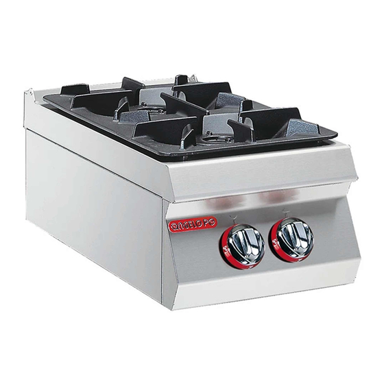
Der Gasherd mit offenen Flammen, der im Folgen- Das Gerät wird bedarfsabhängig in verschiedenen den als Gerät bezeichnet wird, wurde zum Zuberei- Versionen hergestellt (siehe Abbildung). ten und Garen von Speisen in Restaurantbetrieben projektiert und konstruiert. 0G0FA0 1G0FA0 1G0FA0B 6 kW 6 kW 6 kW...
SICHERHEITSVORRICHTUNGEN Das Gerät wird zwar mit sämtlichen planmäßigen Sicherheitsvorrichtungen geliefert, es kann jedoch notwendig sein, während Installation und An- schluss ggf. weitere ergänzende Maßnahmen zu ergreifen, um den Anforderungen der einschlägi- gen geltenden Gesetze zu entsprechen. Die Abbildung zeigt die Anordnung der Sicherheits- vorrichtungen.
SICHERHEIT ALLGEMEINE SICHERHEITSHINWEISE – Der Hersteller hat bei Entwicklung und Fertigung kenntnisse oder besondere Fähigkeiten erfor- dieses Produkts besondere Sorgfalt auf Aspekte dern, dürfen ausschließlich von qualifiziertem verwendet, die eine Gefahr für die Sicherheit und Personal mit nachweislicher Erfahrung in diesem die Gesundheit der Personen, die dieses Gerät speziellen Gebiet des Eingriffs durchgeführt wer- handhaben, hervorrufen können.
SICHERHEITSHINWEISE ZUR ELEKTRISCHEN AUSRÜSTUNG Die elektrische Ausrüstung wurde nach Maßgabe ren, chemische Substanzen, Salze usw.) enthal- der geltenden einschlägigen Bestimmungen pro- ten und dürfen nicht mit den elektrischen jektiert und konstruiert. Die Bestimmungen ziehen Komponenten in Kontakt kommen und/oder in die Betriebsbedingungen auf Grundlage der jewei- sie eindringen.
BESCHREIBUNG DER BEDIENELEMENTE Das Gerät ist mit Bedienele- Anzeige vorderer Anzeige hinterer menten zur Aktivierung der Brenner Brenner wichtigsten Funktionen aus- gestattet. Anzeige Anzeige Ausschaltung A)Schalter des Kochstel- Zündflammenbrenner lenbrenners: zum Ein- und Ausschalten des ent- sprechenden Kochstellen- brenners Anzeige min. Anzeige max.
TIPPS FÜR DEN GEBRAUCH Um eine korrekte Anwendung des Gerätes zu ge- – Das Gerät und den umliegenden Bereich stets währleisten, sollten folgende Ratschläge befolgt sauber halten. werden: – Zum Reinigen nur lebensmitteltaugliche Reiniger – Verwenden Sie ausschließlich das vom Herstel- verwenden.
REINIGUNG DER KOCHMULDE, BRENNER UND ZUBEHÖRTEILE Für diesen Vorgang in der angegebenen Weise verfahren. 1 - Brennerdeckel (A) und Brenner (B) ausbauen. 2 - Den Brenner und den Brennerdeckel gründlich reinigen und sicherstellen, dass die Löcher des Brennerdeckels nicht verstopft sind. 3 - Regelmäßig das Zündloch im Brenner reinigen.
DEFEKTE FEHLERSUCHE Vor der Inbetriebnahme wurde das Gerät einem selbst behoben werden; alle anderen erfordern prä- vorläufigen Testlauf unterzogen. zise Fachkenntnisse oder besondere Fähigkeiten Die im Folgenden aufgeführten Informationen sol- und dürfen daher ausschließlich von qualifiziertem len Ihnen dabei helfen, eventuelle Anomalien oder Personal mit nachweislicher Erfahrung in diesem Funktionsstörungen, die während des Betriebs auf- speziellen Gebiet des Eingriffs durchgeführt wer-...
HANDHABUNG UND INSTALLATION EMPFEHLUNGEN FÜR DIE INSTALLATION UND HANDHABUNG Wichtig Beachten Sie die Hinweise des Herstellers, nen autorisierte Person wird bei Bedarf die direkt auf der Verpackung, auf dem Ge- einen "Sicherheitsplan" aufstellen müssen, rät selbst oder in der Gebrauchsanweisung um die Unversehrtheit der direkt an dem zu finden sind, wenn Sie das Gerät handha- Vorgang beteiligten Personen zu gewähr-...
INSTALLATION DES GERÄTS Es müssen sämtliche Phasen der Installation, schon von der Umsetzung des allgemeinen Projekts an, be- rücksichtigt werden. Die für diese Operationen autori- sierte Person wird vor Einleitung dieser Phasen den Installationsstandort bestimmen und bei Bedarf einen "Sicherheitsplan" aufstellen, um die Unversehrtheit der direkt am Vorgang beteiligten Personen zu gewährlei- sten und die gesetzlichen Bestimmungen zu befolgen.
Für die in Reihe aufgestellten Geräte sind auf An- G)Einbausatz für die Montage auf Unterschrank frage verschiedene Ausstattungssätze lieferbar. H)Einbausatz für Brückenmontage IDM-39614501300.tif GASANSCHLUSS Wichtig Diese Arbeit darf nur von zugelassenen und erfahrenen Fachleuten ausgeführt wer- den. Der Anschluss muss fachgerecht und vorschriftsmäßig ausgeführt werden und allen einschlägigen gesetzlichen Bestim- mungen entsprechen.
UMSTELLUNG DER GASVERSORGUNG Der werkseitig durchgeführte Testlauf ist mit dem Gastyp des örtlichen Gaswerks durchgeführt wor- den. Der Gastyp des Testlaufs ist aus dem Aufkle- ersichtlich, Typenschild angebracht wurde. Falls Sie das Gerät an eine Gaszufuhr anderen Typs anschließen müssen, gehen Sie folgender- maßen vor: 1 - Schließen Sie den Gaszufuhrhahn (A) 2 - Die Düsen der Kochstellenbrenner austau-...
EINSTELLUNGEN EMPFEHLUNGEN FÜR DIE EINSTELLUNGEN Wichtig Vor jeder Regulierung an den Einstellungen den Gashahn ab und verhindern Sie den müssen sämtliche vorgesehenen Sicher- Zugang zu allen Vorrichtungen, die bei ih- heitsvorrichtungen aktiviert werden. Über- rer Aktivierung eine unvorgesehene Gefahr legen Sie, ob es notwendig ist, das hervorrufen und Schäden für die Sicherheit arbeitende Personal und die in der Nähe be- und die Gesundheit von Personen verursa-...
EINSTELLUNG DER PRIMÄRLUFT DES KOCHSTELLENBRENNERS Für diesen Vorgang in der angegebenen Weise montieren Sie die Blende (B) ab. verfahren. 4 - Die Schraube (D) lockern und die Brennerhalte- 1 - Schließen Sie den Gaszufuhrhahn rung (E) bis zum Anschlag anheben. 2 - Den Schalter (A) abziehen.
AUSTAUSCH VON BAUTEILE HINWEISE ZUM AUSTAUSCH VON TEILEN Vor jedem Eingriff zur Ersetzung eines Teils müssen darf Komponenten, die Verschleißerscheinungen zei- sämtliche vorgesehenen Sicherheitsvorrichtungen ak- gen; verwenden dabei ausschließlich tiviert werden. Überlegen Sie, ob es notwendig ist, das Originalersatzteile.Es wird jede Haftung für Personen- arbeitende Personal und die in der Nähe befindlichen oder Komponentenschäden abgelehnt, die entstehen, Personen auf angemessene Weise zu informieren.
AUSTAUSCH DER DÜSE DES ZÜNDFLAMMENBRENNERS DES KOCHSTELLENBRENNERS Für diesen Vorgang in der angegebenen Weise 5 - Nehmen Sie die Düse (E) heraus und ersetzen verfahren. Sie sie mit dem für den betreffenden Gastyp 1 - Schließen Sie den Gaszufuhrhahn geeigneten Bauteil (siehe Tabelle am Ende des 2 - Den Schalter (A) abziehen.
Seite 67
CUCINA FUOCHI APERTI 0G0FA0 OPEN BURNER RANGE 1G0FA0 GASHERD MIT OFFENEN FLAMMEN 2G0FA0 CUISINIÈRE FEUX VIFS 2G0FA0A COCINA FUEGOS ABIERTOS 1G0FA0B 2G0FA0B MANUALE D’USO E INSTALLAZIONE USE AND INSTALLATION MANUAL BEDIEN- UND INSTALLATIONSHANDBUCH MANUEL D’UTILISATION ET D’INSTALLATION MANUAL DE USO E INSTALACIÓN...
INFORMATIONS GÉNÉRALES INFORMATIONS POUR LE LECTEUR Pour retrouver facilement les sujets qui vous inté- 2e partie: elle contient toutes les informa- ressent, consulter l’index analytique au début du tions nécessaires aux destinataires homogè- manuel. nes, c’est-à-dire tous les opérateurs experts Ce manuel est divisé...
IDENTIFICATION DU FABRICANT ET DE L’APPAREIL La plaque d’identification représentée, est appli- ) Type de gaz ) Puissance déclarée (kW) quée directement sur l'appareil. Elle reporte les ré- ) Consommation de gaz férences et les indications indispensables à la ) Indicateur du gaz d’essai sécurité.
été conçu et fabriqué pour la préparation En fonction des exigences d'utilisation, l'appareil et la cuisson d'aliments dans le domaine de la res- est réalisé en plusieurs versions (voir figure). 0G0FA0 1G0FA0 1G0FA0B 6 kW 6 kW...
DISPOSITIFS DE SÉCURITÉ Même si l’appareil est complet de tous les disposi- tifs de sécurité, lors de l’installation et du raccorde- ment, ils devront, si nécessaire, être intégrés avec d’autres pour respecter les lois en vigueur. L’illustration indique la position des dispositifs. A)Robinet d’alimentation du gaz: pour ouvrir et fer- mer le raccordement à...
SÉCURITÉ NORMES DE SÉCURITÉ – Le fabricant, lors de la conception et de la fabri- personnel qualifié, ayant une expérience recon- cation, a fait très attention aux aspects qui peu- nue et acquise dans le secteur spécifique d’inter- vent provoquer des risques à la sécurité et à la vention.
AVERTISSEMENTS DE SÉCURITÉ POUR L’ÉQUIPEMENT ÉLECTRIQUE L'équipement électrique a été conçu et construit (acides, substances chimiques, sels, etc.) et ne conformément aux normes en vigueur en la matiè- doivent pas pouvoir pénétrer dans les compo- re. Ces normes tiennent en considération les condi- sants électriques et/ou entrer en contact avec tions fonctionnement...
DESCRIPTION DES COMMANDES Sur l’appareil sont disposées Symbole brûleur Symbole brûleur les commandes pour activer avant arrière les fonctions principales. Index extinction Index veilleuse A)Manette de commande pilote brûleur fourneau: pour allumer, éteindre et régler le brûleur fourneau correspondant Index puissance Index puissance minimum maximum...
CONSEILS D’UTILISATION Afin de garantir une utilisation correcte de l’appa- – L’appareil et les zones environnantes doivent reil, suivre ces conseils. être constamment propres. – Utiliser exclusivement les accessoires indiqués – Pour le nettoyage, utiliser exclusivement des pro- par le fabricant. duits détergents pour usage alimentaire.
Seite 78
NETTOYAGE DE LA TABLE DE CUISSON, DES BRÛLEURS ET DES ACCESSOIRES Pour cette opération, procéder comme suit. 1 - Démonter la tête de brûleur (A) et le brûleur (B). 2 - Nettoyer soigneusement le brûleur et la tête de brûleur et vérifier que ses trous ne soient pas obs- trués.
Seite 79
PANNES DÉPANNAGE Avant sa mise en service, l’appareil a été essayé. l’utilisateur, pour tous les autres il faut une compé- Les informations reportées ci-après ont pour but tence technique précise capacités d’aider à l'identification et à la correction d’éven- particulières ; ils doivent donc être exécutés exclu- tuels pannes et dysfonctionnements qui pourraient sivement par du personnel qualifié...
MANUTENTION ET INSTALLATION RECOMMANDATIONS POUR LA MANUTENTION ET L’INSTALLATION Important Effectuer la manutention et l’installation en effectuer ces opérations devra, si nécessai- respectant les informations fournies par le re, organiser un « plan de sécurité » pour fabricant, reportées directement sur l’em- sauvegarder la sécurité...
MISE EN PLACE DE L’APPAREIL Toutes les phases de mise en place doivent être prises en considération, dès la réalisation du projet général. Avant de commencer ces phases, outre la définition de la zone de mise en place, celui qui est autorisé à effec- tuer ces opérations devra, si nécessaire, faire un «...
Pour les appareils en batterie, différents kits d’ins- G)Kit pour installation « sur soubassement » tallation sont disponibles, sur demande: H)Kit pour installation « en pont » IDM-39614501300.tif RACCORDEMENT DU GAZ Important La personne autorisée à effectuer cette opération devra avoir les capacités et l’ex- périence acquise et reconnue dans le sec- teur spécifique;...
Seite 83
TRANSFORMATION DE L’ALIMENTATION L'appareil a été essayé par le fabricant avec le gaz de réseau, signalé par l’adhésif collé sur la plaque d’identification. Si le type de gaz à raccorder est différent de celui d’essai, procéder comme suit. 1 - Fermer le robinet d’alimentation du gaz (A). 2 - Remplacer les buses des brûleurs fourneau (voir page 18).
Seite 84
RÉGLAGES RECOMMANDATIONS POUR LES RÉGLAGES Important Avant d’effectuer tout type de réglage, acti- empêcher l’accès à tous les dispositifs qui ver tous les dispositifs de sécurité prévus pourraient, s’ils sont activés, provoquer et évaluer s’il faut informer le personnel qui des conditions de danger inattendu en cau- travaille et celui à...
Seite 85
RÉGLAGE DE L’AIR PRIMAIRE DU BRÛLEUR FOURNEAU Pour cette opération, procéder comme suit. 4 - Desserrer la vis (D) et lever le support du brû- 1 - Fermer le robinet d’alimentation du gaz. leur (E) jusqu’à la butée. 2 - Enlever la manette (A). 5 - Serrer la vis (D) et rétablir les conditions initia- 3 - Dévisser les vis (C) et démonter le tableau de les lorsque l’opération est terminée.
REMPLACEMENT DE PIÈCES RECOMMANDATIONS POUR LE REMPLACEMENT DES PIÈCES Avant d’effectuer tout remplacement, activer tous usés, utiliser exclusivement des pièces de rechan- les dispositifs de sécurité prévus et évaluer s’il faut ge d’origine.Le fabricant décline toute responsabili- informer les opérateurs travaillant sur l'appareil et té...
Seite 87
REMPLACEMENT DE LA BUSE VEILLEUSE PILOTE DU BRÛLEUR FOURNEAU Pour cette opération, procéder comme suit. 5 - Enlever la buse (E) et la remplacer par celle 1 - Fermer le robinet d’alimentation du gaz. adaptée au type de gaz utilisé (voir tableau à la 2 - Enlever la manette (A).
Seite 89
CUCINA FUOCHI APERTI 0G0FA0 OPEN BURNER RANGE 1G0FA0 GASHERD MIT OFFENEN FLAMMEN 2G0FA0 CUISINIÈRE FEUX VIFS 2G0FA0A COCINA FUEGOS ABIERTOS 1G0FA0B 2G0FA0B MANUALE D’USO E INSTALLAZIONE USE AND INSTALLATION MANUAL BEDIEN- UND INSTALLATIONSHANDBUCH MANUEL D’UTILISATION ET D’INSTALLATION MANUAL DE USO E INSTALACIÓN...
Seite 91
ÍNDICE ref. capítulos pág 1 INFORMACIONES DE CARÁCTER GENERAL ....2 2 INFORMACIONES DE CARÁCTER TÉCNICO ....4 3 SEGURIDAD ..............6 PARTE 4 USO Y FUNCIONAMIENTO ..........7 5 MANTENIMIENTO ............. 9 6 AVERÍAS ................11 7 DESPLAZAMIENTO E INSTALACIÓN ......12 8 REGULACIONES .............
INFORMACIONES DE CARÁCTER GENERAL INFORMACIONES PREVIAS Para ubicar fácilmente los temas específicos de in- 2a parte: contiene todas las informaciones ne- terés, consúltese el índice analítico que se encuen- cesarias para destinatarios homogéneos, esto tra al inicio del manual. es, todos los operadores expertos y autorizados Este manual comprende dos partes.
Seite 93
IDENTIFICACIÓN FABRICANTE Y EQUIPO La placa de identificación fijada directamente en el ) Potencia declarada (kW) ) Consumo de gas equipo reproduce todas las referencias e indicacio- ) Indicador gas prueba de funcionamiento nes indispensables para la seguridad de servicio. ) Fecha de fabricación Placa complementaria Placa gas prueba de funcionamiento...
DISPOSITIVOS DE SEGURIDAD Aunque el equipo cuente con todos los dispositivos de seguridad, en los casos en que así lo determi- nen las leyes vigentes en materia, se deberá com- plementar con otros dispositivos en las fases de instalación y enlace. La ilustración indica la posición de los dispositivos.
SEGURIDAD ADVERTENCIAS GENERALES SOBRE SEGURIDAD – Durante las fases de diseño y producción el fabri- das exclusivamente por personal calificado y con cante ha prestado especial atención a los facto- experiencia reconocida y adquirida en el sector res que pueden provocar riesgos en cuanto a específico de la intervención.
ADVERTENCIAS SOBRE SEGURIDAD RELATIVAS A LOS EQUIPOS ELÉCTRICOS Los equipos eléctricos han sido proyectados y fa- nimiento no deben contener agentes contami- bricados en conformidad con lo dispuesto por las nantes corrosivos (ácidos, sustancias respectivas normas vigentes. Dichas normas consi- químicas, sales, etc.) ni ser capaces de penetrar deran las condiciones de funcionamiento según el o entrar en contacto con los componentes eléc-...
DESCRIPCIÓN DE LOS MANDOS Para activar las funciones Índice quemador Índice quemador principales, en el equipo se delantero trasero han instalado los siguientes Índice apagado Índice testigo mandos. piloto A)Mando de control que- mador de plano: para en- cender, apagar y regular el respectivo quemador de plano.
CONSEJOS PARA EL USO A fin de garantizar un uso correcto del equipo, apli- – Mantener constantemente limpio el aparato y las car las siguientes recomendaciones. zonas a él próximas. – Utilizar exclusivamente los accesorios indicados – La limpieza deberá efectuarse utilizando única- por el fabricante.
LIMPIEZA DE ENCIMERA, QUEMADORES Y ACCESORIOS Para efectuar esta operación, aplicar las siguientes ins- trucciones. 1 - Desmontar el casquete quemador (A) y el quema- dor (B). 2 - Limpiar esmeradamente el quemador y el casque- te quemador y verificar que los orificios no estén obstruidos.
AVERÍAS BÚSQUEDA DE AVERÍAS Antes de la puesta en servicio, el equipo ha sido so- por el usuario, pero otros requieren una competen- metido a prueba de funcionamiento. cia técnica precisa o determinadas capacidades, Las siguientes informaciones tienen por objeto faci- razón por la cual deben ser resueltos exclusiva- litar la identificación y corrección de eventuales mente por personal calificado con experiencia reco-...
DESPLAZAMIENTO E INSTALACIÓN RECOMENDACIONES PARA EL DESPLAZAMIENTO Y LA INSTALACIÓN Importante Efectuar el desplazamiento e instalación rizada para efectuar estas operaciones de- respetando las indicaciones proporciona- berá, si fuera necesario, organizar un "plan das por el fabricante, reproducidas directa- de seguridad", a fin de salvaguardar la in- mente sobre el embalaje, en el equipo y en columidad de las personas directamente las instrucciones de uso.
INSTALACIÓN DEL EQUIPO Durante la realización del proyecto general, deben ser consideradas todas las fases de la instalación. Antes de comenzar dichas fases, además de esta- blecer la zona de instalación, la persona autorizada a efectuar estas operaciones deberá, si fuera nece- sario, aplicar un "plan de seguridad"...
Seite 104
En el caso de equipos en batería se encuentran G)Kit para la instalación "en mueble" disponibles, bajo pedido, los siguientes kits: H)Kit para la instalación "de puente" IDM-39614501300.tif ENLACE GAS Importante El personal autorizado para ejecutar esta ope- ración debe poseer capacidad y haber adqui- rido experiencia efectiva...
Seite 105
TRANSFORMACIÓN ALIMENTACIÓN El fabricante ha sometido el equipo a una prueba de funcionamiento con el gas de la red de su propio país, señalándolo con el adhesivo fijado en la placa de identificación. Si el tipo de gas a utilizar es diferente de aquél usa- do en la prueba de funcionamiento, aplicar las si- guientes instrucciones.
REGULACIONES RECOMENDACIONES PARA EFECTUAR LAS REGULACIONES Importante Antes de efectuar cualquier tipo de regula- de alimentación del gas e impedir el acceso ción, activar todos los dispositivos de se- a todos los dispositivos que, en caso de ser guridad previstos y evaluar la conveniencia activados, podrían provocar situaciones de de informar oportunamente tanto al perso- peligro inesperado en cuanto a seguridad y...
Seite 107
REGULACIÓN AIRE PRIMARIO QUEMADOR DE PLANO Para efectuar esta operación, aplicar las siguientes 4 - Afloje el tornillo (D) y eleve el soporte quema- instrucciones. dor (E) hasta topar. 1 - Cerrar el grifo de alimentación del gas. 5 - Para concluir, apriete el tornillo (D) y restablez- 2 - Retirar el mando (A).
SOSTITUCIÓN DE PIEZAS RECOMENDACIONES PARA EFECTUAR LA SUSTITUCIÓN DE LAS PIEZAS Antes de efectuar cualquiera operación de sustitu- se deberán utilizar exclusivamente piezas de re- ción, activar todos los dispositivos de seguridad cambio originales. Se declina toda responsabilidad previstos y evaluar la conveniencia de informar por daños a personas o a componentes del equipo adecuadamente tanto al personal operativo como derivados del empleo de piezas de recambio no ori-...
Seite 109
SUSTITUCIÓN INYECTOR TESTIGO PILOTO QUEMADOR DE PLANO Para efectuar esta operación, aplicar las siguientes 4 - Retirar el tubo (D). instrucciones. 5 - Extraer el inyector (E) y sustituirlo por otro que 1 - Cerrar el grifo de alimentación del gas. sea adecuado para el tipo de gas utilizado 2 - Retirar el mando (A).
Ø110 - 6 kW Modelo (Min. 1,9 kW) 0G0FA0 N. 2 1,27 m 1,48 m 0,95 Kg/h 0,93 Kg/h SCHEDA ALLACCIAMENTI (0G0FA0) - CONNECTION CARD (0G0FA0) - ANSCHLUSSSCHEMA (0G0FA0) - FICHE DES RACCORDEMENTS (0G0FA0) - FICHA DE ENLACES (0G0FA0) IDM-39608801100.tif...
Seite 112
Bruciatori di piano - Top burners Consumo gas - Gas consumption Modello Kochstellenbrenner - Brûleurs fourneau Gasverbrauch - Consommation de gaz Model Quemadores de plano Consumo de gas Modelle Qn kW Modèle Ø80 - 4 kW Ø110 - 6 kW Modelo (Min.
Seite 113
Bruciatori di piano - Top burners Consumo gas - Gas consumption Modello Kochstellenbrenner - Brûleurs fourneau Gasverbrauch - Consommation de gaz Model Quemadores de plano Consumo de gas Modelle Qn kW Modèle Ø110 - 6 kW Modelo (Min. 1,9 kW) 1G0FA0B N.
Seite 114
Bruciatori di piano - Top burners Consumo gas - Gas consumption Modello Kochstellenbrenner - Brûleurs fourneau Gasverbrauch - Consommation de gaz Model Quemadores de plano Consumo de gas Modelle Qn kW Modèle Ø80 - 4 kW Ø110 - 6 kW Modelo (Min.
Seite 115
Bruciatori di piano - Top burners Consumo gas - Gas consumption Modello Kochstellenbrenner - Brûleurs fourneau Gasverbrauch - Consommation de gaz Model Quemadores de plano Consumo de gas Modelle Qn kW Modèle Ø80 - 4 kW Modelo (Min. 1,3 kW) 2G0FA0A N.
Seite 116
Bruciatori di piano - Top burners Consumo gas - Gas consumption Modello Kochstellenbrenner - Brûleurs fourneau Gasverbrauch - Consommation de gaz Model Quemadores de plano Consumo de gas Modelle Qn kW Modèle Ø110 - 6 kW Modelo (Min. 1,9 kW) 2G0FA0B N.
Seite 117
Tabella iniettori bruciatore di piano ø80 - Table of top burner injectors ø80 - Tabelle: Düsen für Kochstellenbrenner ø80 Tableau des injecteurs du brûleur fourneau ø80 - Tabla inyectores quemador de plano ø80 ø (4) ø (5) ø (6) ø (8) Pen mbar Qn max kW p (3) mbar Qn min kW...
Seite 118
Tabella iniettori bruciatore di piano ø80 - Table of top burner injectors ø80 - Tabelle: Düsen für Kochstellenbrenner ø80 Tableau des injecteurs du brûleur fourneau ø80 - Tabla inyectores quemador de plano ø80 ø (4) ø (5) ø (6) ø (8) Pen mbar Qn max kW p (3) mbar Qn min kW...
Seite 119
Tabella iniettori bruciatore di piano ø110 - Table of top burner injectors ø110 - Tabelle: Düsen für Kochstellenbrenner ø110 Tableau des injecteurs du brûleur fourneau ø110 - Tabla inyectores quemador de plano ø110 ø (4) ø (5) ø (6) ø (8) Pen mbar Qn max kW p (3) mbar Qn min kW...
Seite 120
Tabella iniettori bruciatore di piano ø110 - Table of top burner injectors ø110 - Tabelle: Düsen für Kochstellenbrenner ø110 Tableau des injecteurs du brûleur fourneau ø110 - Tabla inyectores quemador de plano ø110 ø (4) ø (5) ø (6) ø (8) Pen mbar Qn max kW p (3) mbar Qn min kW...
Seite 121
Tabella caratteristiche gas - Table of gas characteristics - Tabelle der Gas-Eigenschaften Tableau des caractéristiques du gaz - Tabla características gas Potere calorifero inferiore (Hi) Famiglia Tipo di gas Indice Wobbe (MJ/m Net calorific value (Hi) Group Gas type Wobbe index (MJ/m Unterer Heizwert (Hi) Familie Gastypen...