Herunterladen Inhalt Inhalt Diese Seite drucken
Angelo Po 1G1PE2EV Bedien- Und Installationshandbuch

Angelo Po 1G1PE2EV Bedien- Und Installationshandbuch

Platten-elektrokochherd+backofen
Inhaltsverzeichnis

Werbung

Verfügbare Sprachen
  • DE

Verfügbare Sprachen

  • DEUTSCH, seite 39
PIASTRE ELETTRICHE + FORNO
PLATTEN-ELEKTROKOCHHERD + BACKOFEN
PLAQUES ÉLECTRIQUES + FOUR
PLANCHAS ELÉCTRICAS + HORNO
ELECTRIC PLATES + OVEN
MANUALE D'USO E INSTALLAZIONE
BEDIEN- UND INSTALLATIONSHANDBUCH
MANUEL D'UTILISATION ET D'INSTALLATION
1G1PE1EV - 1G1PE2EV
2G1PE1EV - 2G1PE2EV
USE AND INSTALLATION MANUAL
MANUAL DE USO E INSTALACIÓN
IT
Italiano
GB
English
DE
Deutsch
FR
Français
ES
Español
Ed. 0
03/2010
3175520

Werbung

Inhaltsverzeichnis
loading

Inhaltszusammenfassung für Angelo Po 1G1PE2EV

  • Seite 1 PIASTRE ELETTRICHE + FORNO ELECTRIC PLATES + OVEN 1G1PE1EV - 1G1PE2EV PLATTEN-ELEKTROKOCHHERD + BACKOFEN 2G1PE1EV - 2G1PE2EV PLAQUES ÉLECTRIQUES + FOUR PLANCHAS ELÉCTRICAS + HORNO MANUALE D’USO E INSTALLAZIONE USE AND INSTALLATION MANUAL BEDIEN- UND INSTALLATIONSHANDBUCH MANUEL D’UTILISATION ET D’INSTALLATION MANUAL DE USO E INSTALACIÓN...
  • Seite 3: Inhaltsverzeichnis

    INDICE rif. capitoli pag. 1 INFORMAZIONI GENERALI ..........2 2 INFORMAZIONI TECNICHE ..........3 3 SICUREZZA ............... 6 PARTE 4 USO E FUNZIONAMENTO ..........7 5 MANUTENZIONI .............. 11 6 GUASTI ................13 7 MOVIMENTAZIONE E INSTALLAZIONE ......14 8 REGOLAZIONI..............18 PARTE 9 SOSTITUZIONE PARTI ...........
  • Seite 4: Informazioni Generali

    INFORMAZIONI GENERALI RACCOMANDAZIONI PER IL LETTORE Per rintracciare facilmente gli argomenti specifici di parte: contiene tutte le informazioni ne- cessarie ai destinatari omogenei, cioè tutti gli interesse, consultare l’indice analitico posto all’ini- operatori esperti e autorizzati a movimentare, zio del manuale. trasportare, installare, mantenere, riparare e Questo manuale è...
  • Seite 5: Modalità Di Richiesta Assistenza

    In funzione delle esigenze di utilizzo, l'apparecchia- chiatura, sono state progettate e costruite per la tura è prodotta in più versioni (vedi figura). cottura indiretta dei cibi, nell'ambito della ristorazio- ne professionale. 1G1PE1EV 2G1PE1EV 1G1PE2EV 2G1PE2EV - 3 - Italiano...
  • Seite 6: Dati Tecnici

    Organi principali A)Piastra di cottura: è realizzata in ghisa. B)Manopola comando piastra: serve per regolare la potenza di riscaldamento. C)Manopola comando forno: per attivare e disattiva- re le resistenze del forno e per regolare la tempera- tura all'interno del forno. D)Spia termostato: per segnalare l'intervento del ter- mostato di sicurezza.
  • Seite 7: Segnali Di Sicurezza E Informazione

    SEGNALI DI SICUREZZA E INFORMAZIONE L'illustrazione indica la posizione dei segnali applicati. A)Targa identificazione costruttore e apparec- chiatura. B)Pericolo di scottatura: fare attenzione alle su- perfici calde. C)Pericolo generico: durante il lavaggio dell'appa- recchiatura non dirigere getti d'acqua in pressio- ne sulle parti interne.
  • Seite 8: Sicurezza

    SICUREZZA NORME PER LA SICUREZZA Il costruttore, in fase di progettazione e costruzione, cità devono essere eseguiti esclusivamente da per- ha posto particolare attenzione agli aspetti che pos- sonale qualificato, con esperienza riconosciuta e sono provocare rischi alla sicurezza e alla salute acquisita nel settore specifico di intervento.
  • Seite 9: Uso E Funzionamento

    A tale scopo, il costruttore fornisce alcune indica- In riferimento alla direttiva RAEE 2002/96 (Rifiuti di zioni che dovranno essere considerate da tutti colo- Apparecchiature Elettriche ed Elettroniche), l'utiliz- sono autorizzati interagire zatore, in fase di dismissione, deve smaltire le ap- l'apparecchiatura nell'arco della sua vita prevista, parecchiature negli appositi centri di raccolta per prevenire l'impatto ambientale.
  • Seite 10: Descrizione Comandi

    DESCRIZIONE COMANDI Sull'apparecchiatura sono disposti i comandi per at- C)Spia termostato: per segnalare l'intervento del tivare le funzioni principali. termostato di sicurezza. A)Manopola comando piastre: serve per attivare, D)Spia temperatura: per segnalare la fase di ri- disattivare e regolare le piastre di riscaldamento. scaldamento del forno, a temperatura raggiunta B)Manopola comando forno: per attivare e disat- la spia si spegne.
  • Seite 11 ACCENSIONE E SPEGNIMENTO PIASTRA Accensione Alla prima accensione eseguire una fase di preri- scaldamento delle piastre alla massima potenza, per circa 4 minuti, in assenza di pentole. 1 - Agire sull'interruttore automatico sezionatore per attivare l'allacciamento alla linea elettrica principale. 2 - Ruotare la manopola (A) in posizione 1, per at- tivare la piastra di riscaldamento alla potenza massima.
  • Seite 12: Consigli Per L'uso

    2 - Ruotare la manopola (B) in posizione 1, fra la 3 - Ruotare la manopola (B) in senso antiorario temperatura minima e massima e attendere il (pos 2) per attivare la resistenza superiore in tempo di preriscaldamento prima di utilizzare il funzione dei tipi di cottura.
  • Seite 13: Manutenzioni

    – Verificare il corretto posizionamento della suola – Mantenere costantemente pulita l'apparecchiatu- del forno. ra e le zone limitrofe. – Eseguire una fase di preriscaldamento prima di – Per la pulizia utilizzare esclusivamente prodotti utilizzare il forno. detergenti per uso alimentare. –...
  • Seite 14: Pulizia Forno

    5 - Prestare attenzione alle superfici in acciaio inox Cautela - Avvertenza per non danneggiarle. In particolare, evitare Non usare prodotti che contengono sostanze l'uso di prodotti corrosivi e non utilizzare mate- dannose e pericolose per la salute delle per- riale abrasivo o utensili taglienti.
  • Seite 15: Guasti

    GUASTI RICERCA GUASTI L'apparecchiatura, prima della messa in servizio, è dall’utilizzatore, per tutti gli altri è richiesta una pre- stata preventivamente collaudata. Le informazioni cisa competenza tecnica o particolari capacità e di seguito riportate hanno lo scopo di aiutare l'iden- quindi devono essere eseguiti esclusivamente da tificazione e correzione di eventuali anomalie e di- personale qualificato con esperienza riconosciuta e...
  • Seite 16: Movimentazione E Installazione

    MOVIMENTAZIONE E INSTALLAZIONE RACCOMANDAZIONI PER LA MOVIMENTAZIONE E INSTALLAZIONE Importante Eseguire la movimentazione e l'installazio- Chi è autorizzato ad eseguire queste opera- ne nel rispetto delle informazioni fornite dal zioni dovrà, se necessario, organizzare un costruttore e riportate direttamente sull'im- "piano di sicurezza"...
  • Seite 17: Movimentazione E Sollevamento

    MOVIMENTAZIONE E SOLLEVAMENTO L'apparecchiatura può essere movimentata con un dispositivo di sollevamento a forche o a gancio di portata adeguata. Prima di effettuare questa opera- zione, controllare la posizione del baricentro del ca- rico. IDM-39611801100.tif INSTALLAZIONE APPARECCHIATURA Tutte le fasi di installazione devono essere conside- rate sin dalla realizzazione del progetto generale.
  • Seite 18: Montaggio Apparecchiature In Batteria

    LIVELLAMENTO Agire sui piedi di appoggio (A) per livellare l'appa- recchiatura. IDM-39614401600.tif MONTAGGIO APPARECCHIATURE IN BATTERIA Per montare le apparecchiature in batteria (fianco a fianco) procedere nel modo indicato. 1 - Sfilare le manopole (A). 2 - Svitare le viti (C) e smontare i cruscotti (B). 3 - Applicare, sui bordi da accostare, del na- stro adesivo di protezione.
  • Seite 19: Allacciamento Elettrico

    ALLACCIAMENTO ELETTRICO 1 - Installare, se non è presente, un interruttore se- Importante zionatore (A) vicino all'apparecchiatura con sganciatore magnetotermico e blocco differen- L'allacciamento deve essere effettuato da personale autorizzato e qualificato, nel ri- ziale. spetto delle leggi vigenti in materia e con 2 - Sfilare le manopole (B).
  • Seite 20: Regolazioni

    REGOLAZIONI MODALITÀ PER LE REGOLAZIONI Le funzioni principali dell'apparecchiatura non pre- vedono particolari interventi di regolazione da parte di personale specializzato se non le regolazioni eseguite in fase d'uso dall'utente. SOSTITUZIONE PARTI RACCOMANDAZIONI PER LA SOSTITUZIONE PARTI Prima di effettuare qualsiasi intervento di sostituzio- sando danni alla sicurezza e alla salute delle perso- ne, attivare tutti i dispositivi di sicurezza previsti e va- ne.
  • Seite 21 CONTENTS ref. chapters page 1 GENERAL INFORMATION ..........2 2 TECHNICAL INFORMATION ..........3 3 SAFETY ................6 PART 4 USE AND OPERATION ............. 7 5 SERVICING ..............11 6 FAULT ................13 7 HANDLING AND INSTALLATION ........14 8 ADJUSTMENTS ............... 18 PART 9 REPLACING PARTS ............
  • Seite 22: General Information

    GENERAL INFORMATION INFORMATION FOR THE READER To find the specific topics of interest to you quickly, 2nd part: contains all the information neces- refer to the index at the start of the manual. sary for special categories of reader, i.e. all This manual is subdivided into two parts.
  • Seite 23: Technical Information

    The electric plates, referred to from now on as the The appliance is produced in several versions to appliance, is designed and produced for indirect meet varying user requirements (see diagram). food coooking in the professional catering sector. 1G1PE1EV 2G1PE1EV 1G1PE2EV 2G1PE2EV - 3 - English...
  • Seite 24: Technical Data

    Main Parts A)Cooking plate: constructed in cast iron. B)Plate control knob: sets the heating power. C)Heating element control knob: for turning the oven heating elements on and off (For version 191PE4E only). D)Thermostat light: indicates that the safety thermo- stat has tripped. E)Temperature light: indicates that heating of the oven is in progress.
  • Seite 25: Safety And Information Signs

    SAFETY AND INFORMATION SIGNS The illustration shows the position of the signs pro- vided. A)Nameplate with manufacturer and appliance data. B)Burn hazard: watch out for hot surfaces. C)General hazard: read the manual carefully be- fore carrying out any procedure. D)General hazard: when washing the appliance do not point pressurised water jets at internal parts.
  • Seite 26: Safety

    SAFETY SAFETY REGULATIONS During design and construction, the constructor has To maintain hygiene and protect the food proc- paid special attention to factors which may cause essed from all forms of contamination, all elements risks to the health and safety of the people interact- in direct or indirect contact with foodstuffs and all ing with the appliance.
  • Seite 27: Use And Operation

    For this purpose, the manufacture supplies informa- Under the WEEE (Waste Electrical and Electronic tion which must be considered by all those author- Equipment) Directive 2002/96/EC, when scrapping ised to interact with the appliance during its equipment the user must dispose of it at the specific expected lifetime, in order to prevent environmental authorised disposal centres, or reconsign it, still in- impact.
  • Seite 28: Description Of Controls

    DESCRIPTION OF CONTROLS The appliance is fitted with the controls for use of its C)Thermostat light: indicates that the safety thermo- main functions. stat has tripped. A)Plate control knob: turns the plates on and off D)Temperature light: indicates that heating of the and sets their level.
  • Seite 29: Switching The Oven On And Off

    PLATE ON AND OFF Lighting When first using the plate, pre-heat it at full power without a pan for around 4 minutes. 1 - Turn on the appliance's circuit breaker to con- nect it to the electrical mains. 2 - Turn the knob (A) to position 1 to turn the plate to full power.
  • Seite 30 2 - Turn the knob (B) to 1, between the minimum 3 - Turn the knob (B) anti-clockwise (pos. 2) to turn and maximum temperature, and wait for the on the top heating element, depending on the warm-up time before using the oven (See table). cooking mode required.
  • Seite 31: Servicing

    – Check that the oven bottom plate is positioned – Always keep the appliance and the surrounding correctly. areas clean. – Allow the oven to warm up before using it. – When cleaning, use only food-approved deter- – Do not use the oven with the door part open. gents.
  • Seite 32 5 - Take special care not to damage stainless steel Caution - warning surfaces. In particular, avoid the use of corro- Never use products containing substances sive products and do not use abrasive materials harmful or hazardous for health (solvents, pe- or sharp tools.
  • Seite 33: Fault

    FAULT TROUBLESHOOTING The appliance has been tested before being put The user can solve some of these problems him- into service. self, but for others specific technical knowledge or The information provided below is intended to as- skill is required, and so they must only be carried sist in the identification and correction of any anom- out by qualified staff with recognised experience ac- alies and malfunctions which might occur during...
  • Seite 34: Handling And Installation

    HANDLING AND INSTALLATION RECOMMENDATIONS FOR HANDLING AND INSTALLATION Important When handling and installing the appliance use. If necessary, the person authorised to comply with the information provided by carry out these operations must organise a the constructor directly on the packaging, "safety plan"...
  • Seite 35: Installation Of The Appliance

    HANDLING AND LIFTING The appliance can be handled using fork-lift or hook equipment of suitable load-carrying capacity. Be- fore lifting, check the position of the load's centre of gravity. IDM-39611801100.tif INSTALLATION OF THE APPLIANCE All installation stages must be considered right from production of the general layout.
  • Seite 36: Assembly Appliances In Banks

    LEVELLING Adjust the floor-mounted feet (A) to level the appli- ance. IDM-39614401600.tif ASSEMBLY APPLIANCES IN BANKS To assemble appliances in banks (side by side) proceed as described below. 1 - Pull off the knob (A). 2 - Undo the screws (C) and remove the control panels (B).
  • Seite 37: Electrical Connection

    ELECTRICAL CONNECTION 2 - Pull off the knob (B). Important 3 - Undo the screws (C) and remove the control panel (D). The connection must be made by author- ised, skilled personnel, in accordance with 4 - Connect the circuit-breaker (A) to the terminal the relevant legal requirements, using ap- board (E) of the appliance as shown in the dia- propriate and specified materials.
  • Seite 38: Adjustments

    ADJUSTMENTS ADJUSTMENTS PROCEDURE The appliance's main functions do not require any special adjustments by specialist staff except the settings made during use by the user. REPLACING PARTS RECOMMENDATIONS FOR REPLACING PARTS Before carrying out any replacement procedure, ac- The manufacturer declines all responsibly for injury tivate all the safety devices provided and decide or damage to components due to the use of non whether staff at work and those in the vicinity...
  • Seite 39 INHALTSVERZEICHNIS Ref. Kapitel Seite 1 ALLGEMEINES ..............2 2 TECHNISCHE INFORMATIONEN ........3 3 SICHERHEIT ..............6 1. TEIL 4 GEBRAUCH UND BETRIEB ..........7 5 WARTUNG ............... 11 6 DEFEKTE ................. 13 7 HANDHABUNG UND INSTALLATION ......14 8 EINSTELLUNGEN ............18 2.
  • Seite 40: Allgemeines

    ALLGEMEINES INFORMATIONEN FÜR DEN LESER Konsultieren Sie das Sachregister, das am Anfang 2. Teil: Diese Informationen wenden sich an des Handbuchs zu finden ist, um leichter unter be- eine bestimmte Zielgruppe. Sie sind für erfahre- stimmten Themen von besonderem Interesse ne Bediener bestimmt, die für Handhabung, nachschlagen zu können.
  • Seite 41: Kundendienst Anfordern

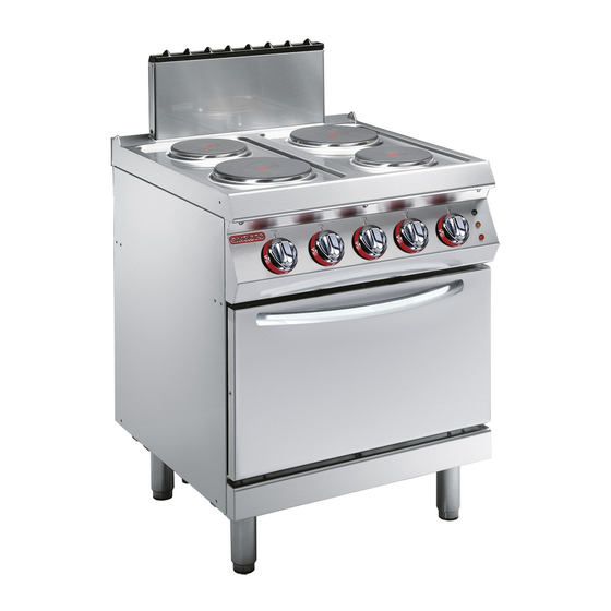
    Die Elektro-Kochplatten, die im Folgenden als Ge- Das Gerät wird bedarfsabhängig in verschiedenen rät bezeichnet werden, wurden für den Gebrauch in Versionen hergestellt (siehe Abbildung). Restaurantbetrieben zum indirekten Garen von Speisen projektiert und konstruiert. 1G1PE1EV 2G1PE1EV 1G1PE2EV 2G1PE2EV - 3 - Deutsch...
  • Seite 42: Technische Daten

    Hauptorgane A)Kochplatte: aus Gusseisen. B)Schalter der Kochplatte: Er dient zum Einstellen der Heizleistung. C)Backofen-Schalter:zum Ein- und Ausschalten der Heizwiderstände des Backofens und er dient zum Einstellen der Temperatur im Backofen. D)Thermostat-Kontrollleuchte: Sie signalisiert die Auslösung des Sicherheitsthermostaten. E)Kontrollleuchte Temperatur: Sie signalisiert die Heizphasen des Backofens.
  • Seite 43: Sicherheitshinweise Und Informationen

    SICHERHEITSHINWEISE UND INFORMATIONEN Die Abbildung zeigt die Anordnung der aufgekleb- ten Sicherheitshinweise. A)Typenschild mit Angabe des Herstellers und der Gerätekenndaten. B)Verbrennungsgefahr: Vorsicht vor heißen Flächen. C)Allgemeine Gefahr: Vor Ausführung irgendeines Eingriffs zuerst das Handbuch aufmerksam lesen. D)Allgemeine Gefahr: Beim Waschen des Geräts den Wasserstrahl nicht direkt auf die inneren Teile richten.
  • Seite 44: Sicherheit

    SICHERHEIT SICHERHEITSVORSCHRIFTEN Der Hersteller hat bei Entwicklung und Fertigung die- Sämtliche Wartungsarbeiten, die präzise Fachkennt- ses Produkts besondere Sorgfalt auf Aspekte ver- nisse oder besondere Fähigkeiten erfordern, dürfen wendet, die eine Gefahr für die Sicherheit und die ausschließlich von qualifiziertem Personal mit nach- Gesundheit der Personen, die dieses Gerät handha- weislicher Erfahrung in diesem speziellen Gebiet ben, hervorrufen können.
  • Seite 45: Teil 4 Gebrauch Und Betrieb

    Zu diesem Zweck gibt der Hersteller einige Hinwei- Gemäß der WEEE-Richtlinie 2002/96/EG (Elektro- se, die von jedem, der zur Interaktion mit dem Gerät und Elektronik-Altgeräte) muss der Betreiber bei während seines vorgesehenen Lebenszyklus be- der endgültigen Außerbetriebnahme die Geräte bei rechtigt ist, beachtet werden müssen, um die Um- den hierfür vorgesehenen Rücknahmestellen abge- weltbelastung auf ein Minimum zu reduzieren.
  • Seite 46: Beschreibung Der Bedienelemente

    BESCHREIBUNG DER BEDIENELEMENTE Das Gerät ist mit Bedienelementen zur Aktivierung C)Thermostat-Kontrollleuchte: Sie signalisiert die der wichtigsten Funktionen ausgestattet. Auslösung des Sicherheitsthermostaten. A)Schalter Kochplatten: zur Einschaltung, Aus- D)Kontrollleuchte Temperatur: Sie signalisiert die schaltung und Regelung der Kochplatten. Heizphasen des Backofens; sie erlischt nach Errei- B)Backofen-Schalter:zum Ein- und Ausschalten der chen der Temperatur.
  • Seite 47: Ein- Und Ausschalten Der Kochplatte

    EIN- UND AUSSCHALTEN DER KOCHPLATTE Zündung Bei der ersten Einschaltung eine Vorheizphase der Kochplatten ca. 4 Minuten mit maximaler Leistung und ohne Kochtöpfe ausführen. 1 - Mit dem Trennschalter den Anschluss an das Stromnetz herstellen. 2 - Den Schalter (A) in die Stellung 1 drehen, um die Kochplatte auf die maximale Leistung ein- zuschalten.
  • Seite 48: Rücksetzen Des Geräts

    Die Stromzufuhr-Kontrollleuchte (E) und die Tem- 3 - Den Schalter (B) entgegen dem Uhrzeigersinn (Pos. 2) drehen, um je nach gewünschter Be- peratur-Kontrollleuchte (D) werden eingeschaltet, heizungsart die obere oder die untere Heizwi- um zu signalisieren, dass der Backofen nicht die derstände einzuschalten.
  • Seite 49: Wartung

    – Sicherstellen, dass das Bodenblech richtig ein- schalten. gesetzt ist. – Das Gerät und den umliegenden Bereich stets – Den Backofen vor dem Gebrauch vorheizen. sauber halten. – Den Backofen nicht mit teilweise geöffneter Tür – Zum Reinigen nur lebensmitteltaugliche Reiniger verwenden.
  • Seite 50: Reinigung Des Backofens

    5 - Behandeln Sie die Edelstahlflächen vorsichtig, Vorsicht - Achtung um sie nicht zu beschädigen. Insbesondere Verwenden Sie keine Produkte, die Stoffe ent- sollte der Gebrauch von ätzenden Produkten, halten, welche für die menschliche Gesund- Scheuermitteln und spitzen Gegenständen ver- heit schädlich gefährlich...
  • Seite 51: Defekte

    DEFEKTE FEHLERSUCHE Vor der Inbetriebnahme wurde das Gerät einem selbst behoben werden; alle anderen erfordern prä- vorläufigen Testlauf unterzogen. zise Fachkenntnisse oder besondere Fähigkeiten Die im Folgenden aufgeführten Informationen sol- und dürfen daher ausschließlich von qualifiziertem len Ihnen dabei helfen, eventuelle Anomalien oder Personal mit nachweislicher Erfahrung in diesem Funktionsstörungen, die während des Betriebs auf- speziellen Gebiet des Eingriffs durchgeführt wer-...
  • Seite 52: Handhabung Und Installation

    HANDHABUNG UND INSTALLATION EMPFEHLUNGEN FÜR DIE INSTALLATION UND HANDHABUNG Wichtig Beachten Sie die Hinweise des Herstellers, nen autorisierte Person wird bei Bedarf die direkt auf der Verpackung, auf dem Ge- einen „Sicherheitsplan" aufstellen müssen, rät selbst oder in der Gebrauchsanweisung um die Unversehrtheit der direkt an dem zu finden sind, wenn Sie das Gerät handha- Vorgang beteiligten Personen zu gewähr-...
  • Seite 53: Handhabung Und Hub

    HANDHABUNG UND HUB Das Gerät kann mit einem Hubmittel bewegt wer- den, das mit Gabeln oder Haken ausgestattet ist und die geeignete Traglast besitzt. Vor diesem Vor- gang ist der Schwerpunkt der Last zu überprüfen. IDM-39611801100.tif INSTALLATION DES GERÄTS Es müssen sämtliche Phasen der Installation, schon von der Umsetzung des allgemeinen Projekts an, be- rücksichtigt werden.
  • Seite 54: Nivellieren

    NIVELLIEREN Regulieren Sie die Füße (A), um das Gerät wasser- waagengerecht aufzustellen. IDM-39614401600.tif MONTAGE BEI REIHENAUFSTELLUNG Verfahren Sie folgendermaßen, um Geräte (neben- einander) in einer Reihe aufzustellen. 1 - Den Schalter (A) abziehen. 2 - Die Schrauben (C) ausschrauben und die Blenden (B) ausbauen.
  • Seite 55: Stromanschluss

    STROMANSCHLUSS 1 - Falls nicht schon vorhanden, einen Trennschal- Wichtig ter (A) mit thermomagnetischem Auslöser und FI-Block in der Nähe des Geräts installieren. Der Anschluss muss von autorisiertem Fachpersonal in Einklang mit den einschlä- 2 - Den Schalter (B) abziehen. gigen gesetzlichen Bestimmungen und un- 3 - Drehen Sie die Schrauben (C) heraus und Verwendung...
  • Seite 56: Einstellungen

    EINSTELLUNGEN EINSTELLUNGSVERFAHREN Die wichtigsten Funktionen des Geräts erfordern keine besonderen Einstellungen durch Fachperso- nal, sondern können während des Gebrauchs vom Benutzer geregelt werden. AUSTAUSCH VON BAUTEILE HINWEISE ZUM AUSTAUSCH VON TEILEN Vor Ausführung eines Austauschs alle vorgesehenen sundheit von Personen beeinträchtigen könnten. Zum Sicherheitseinrichtungen einschalten und in Erwä- Ersetzen von verschlissenen Komponenten aus- gung ziehen, ob eine angemessene Unterrichtung...
  • Seite 57 INDEX réf. chapitres page 1 INFORMATIONS GÉNÉRALES ......... 2 2 INFORMATIONS TECHNIQUES ........3 3 SÉCURITÉ ................. 6 PARTIE 4 UTILISATION ET FONCTIONNEMENT ......7 5 ENTRETIEN ..............11 6 PANNES ................13 7 MANUTENTION ET INSTALLATION ....... 14 8 RÉGLAGES ..............18 PARTIE 9 REMPLACEMENT DE PIÈCES ........
  • Seite 58: But Du Manuel

    INFORMATIONS GÉNÉRALES INFORMATIONS POUR LE LECTEUR Pour retrouver facilement les sujets qui vous inté- 2e partie : elle contient toutes les informa- ressent, consulter l’index analytique au début du tions nécessaires aux destinataires homogè- manuel. nes, c’est-à-dire tous les opérateurs experts Ce manuel est divisé...
  • Seite 59: Demande D'assistance

    En fonction des exigences d'utilisation, l'appareil nant appareil, ont été conçues et fabriquées pour la est réalisé en plusieurs versions (voir figure). cuisson indirecte d'aliments, dans le domaine de la restauration professionnelle. 1G1PE1EV 2G1PE1EV 1G1PE2EV 2G1PE2EV - 3 - Français...
  • Seite 60: Données Techniques

    Organes principaux A)Plaque de cuisson: elle est réalisée en fonte. B)Manette de commande de la plaque: elle sert pour régler la puissance de chauffe. C)Manette de commande du four: pour activer et dé- sactiver les résistances du four et pour régler la tem- pérature à...
  • Seite 61: Accessoires Sur Demande

    SIGNAUX DE SÉCURITÉ ET INFORMATION L’illustration indique la position des signaux appli- qués. A)Plaque d'identification du fabricant et de l'ap- pareil. B)Risque de brûlure: attention aux surfaces chaudes. C)Danger générique: avant tout type d’intervention, lire attentivement ce manuel. D)Risque générique: pendant le lavage de l’appareil ne pas diriger de jets d’eau sous pression sur les piè- ces intérieures.
  • Seite 62: Normes De Sécurité

    SÉCURITÉ NORMES DE SÉCURITÉ Le fabricant, lors de la conception et de la fabrica- Tous les entretiens qui demandent une compéten- tion, a fait très attention aux aspects qui peuvent ce technique précise ou des capacités particulières provoquer des risques à la sécurité et à la santé des ne peuvent être exécutés que par du personnel personnes qui interagissent avec l’appareil.
  • Seite 63: Recommandations Pour L'utilisation

    Pour cela le fabricant fournit quelques indications En référence à la Directive DEEE 2002/96/CE (dé- qui devront être considérées par tous ceux autori- chets d’équipements électriques et électroniques), sés à interagir avec l'appareil au cours de sa vie l'utilisateur, lorsqu’il veut éliminer les appareils, doit prévue, pour prévenir l'impact environnemental.
  • Seite 64: Description Des Commandes

    DESCRIPTION DES COMMANDES Sur l’appareil sont disposées les commandes pour C)Voyant du thermostat: pour signaler l’intervention activer les fonctions principales. du thermostat de sécurité. A)Manette de commande des plaques: elle sert D)Voyant de la température: pour signaler la phase pour activer, désactiver et régler les plaques de de chauffage du four;...
  • Seite 65 ALLUMAGE ET EXTINCTION DE LA PLAQUE Allumage Au premier allumage, préchauffer les plaques à la puissance maximum, pendant environ 4 minute, sans casseroles. 1 - Agir sur l'interrupteur sectionneur automatique pour activer le branchement à la ligne électri- que principale. Le voyant de réseau (E) s’allume 2 - Tourner la manette (A) en position 1, pour acti- ver la plaque de chauffe à...
  • Seite 66: Conseils D'utilisation

    2 - Tourner la manette (B) sur 1, entre la température 3 - Tourner la manette (B) en sens anti-horaire minimale et maximale, et attendre le temps de (pos 2) pour activer la résistance supérieure en préchauffage avant d’utiliser le four (Voir tableau). fonction des types de cuisson.
  • Seite 67: Recommandations Pour L'entretien

    – Vérifier le positionnement correct de la sole du – L’appareil et les zones environnantes doivent four. être constamment propres. – Préchauffer le four avant son utilisation. – Pour le nettoyage, utiliser exclusivement des pro- – Éviter d’utiliser le four avec la porte partiellement duits détergents pour usage alimentaire.
  • Seite 68: Nettoyage Du Four

    5 - De faire attention aux surfaces en acier inox Attention pour ne pas les endommager. En particulier, Ne pas utiliser de produits qui contiennent éviter l’utilisation de produits corrosifs, ne pas des substances dangereuses pour la santé utiliser de matériau abrasif ou d’outils tran- des personnes (solvants, essences, etc.).
  • Seite 69 PANNES DÉPANNAGE Avant sa mise en service, l’appareil a été essayé. l’utilisateur, pour tous les autres il faut une compé- Les informations reportées ci-après ont pour but tence technique précise ou des capacités particu- d’aider à l'identification et à la correction d’éven- lières;...
  • Seite 70: Emballage Et Déballage

    MANUTENTION ET INSTALLATION RECOMMANDATIONS POUR LA MANUTENTION ET L’INSTALLATION Important Effectuer la manutention et l’installation en effectuer ces opérations devra, si nécessai- respectant les informations fournies par le re, organiser un « plan de sécurité » pour fabricant, reportées directement sur l’em- sauvegarder la sécurité...
  • Seite 71: Manutention Et Levage

    MANUTENTION ET LEVAGE L'appareil peut être manutentionné avec un dispo- sitif de levage à fourches ou à crochet d’une capa- cité de charge appropriée. Avant d’effectuer cette opération, contrôler la position du centre de gravité de la charge. IDM-39611801100.tif MISE EN PLACE DE L’APPAREIL Toutes les phases de mise en place doivent être prises en considération, dès la réalisation du projet général.
  • Seite 72: Mise À Niveau

    MISE À NIVEAU Agir sur les pieds d’appui (A) pour mettre de niveau l’appareil. IDM-39614401600.tif MONTAGE DES APPAREILS EN BATTERIE Pour monter les appareils en batterie (les uns à côté des autres), procéder comme suit. 1 - Enlever la manette (A). 2 - Dévisser les vis (C) et démonter les ta- bleaux de commandes (B).
  • Seite 73: Branchement Électrique

    BRANCHEMENT ÉLECTRIQUE 2 - Enlever la manette (B). Important 3 - Dévisser les vis (C) et démonter le tableau de commandes (D). Le branchement doit être fait par du per- sonnel autorisé et qualifié, conformément 4 - Connecter l'interrupteur sectionneur (A) au bor- aux lois en vigueur à...
  • Seite 74 RÉGLAGES MODES DE RÉGLAGES Les fonctions principales de l’appareil ne prévoient pas d'interventions particulières de réglage par du personnel spécialisé sauf les réglages effectués lors de l'utilisation par l'usager. REMPLACEMENT DE PIÈCES RECOMMANDATIONS POUR LE REMPLACEMENT DES PIÈCES Avant d’effectuer tout remplacement, activer tous les ment des pièces de rechange d’origine.Le fabricant dispositifs de sécurité...
  • Seite 75 ÍNDICE ref. capítulos pág 1 INFORMACIONES DE CARÁCTER GENERAL ....2 2 INFORMACIONES DE CARÁCTER TÉCNICO ....3 3 SEGURIDAD ..............6 PARTE 4 USO Y FUNCIONAMIENTO ..........7 5 MANTENIMIENTO ............11 6 AVERÍAS ................13 7 DESPLAZAMIENTO E INSTALACIÓN ......14 8 REGULACIONES .............
  • Seite 76: Informaciones De Carácter General

    INFORMACIONES DE CARÁCTER GENERAL INFORMACIONES PREVIAS Para ubicar fácilmente los temas específicos de in- 2a parte: contiene todas las informaciones terés, consúltese el índice analítico que se encuen- necesarias para destinatarios homogéneos, tra al inicio del manual. esto es, todos los operadores expertos y au- Este manual comprende dos partes.
  • Seite 77: Informaciones De Carácter Técnico

    El aparato es producido en varias versiones en fun- llamaremos aparato, han sido proyectadas y fabri- ción de los requerimientos específicos de uso (véa- cadas para la cocción indirecta de alimentos en el se figura). sector de la restauración profesional. 1G1PE1EV 2G1PE1EV 1G1PE2EV 2G1PE2EV - 3 - Español...
  • Seite 78: Datos Técnicos

    Órganos principales A)Plancha de cocción: fabricada en fundición. B)Mando de control plancha: sirve para regular la potencia de calentamiento. C)Mando de control horno: sirve para activar y des- activar las resistencias del horno y para regular la temperatura en el interior del horno. D)Testigo termostato: señala la intervención del ter- mostato de seguridad.
  • Seite 79: Accesorios Bajo Pedido

    SEÑALIZACIONES DE SEGURIDAD E INFORMACIÓN La ilustración indica la posición de las señalizacio- nes fijadas en el equipo. A)Placa de identificación fabricante y aparato. B)Peligro de quemaduras: prestar atención a las su- perficies calientes. C)Peligro genérico: antes de efectuar cualquier tipo de intervención leer atentamente el manual.
  • Seite 80: Seguridad

    SEGURIDAD NORMAS DE SEGURIDAD Durante las fases de diseño y producción el fabri- Todas las intervenciones de mantenimiento que re- cante ha prestado especial atención a los factores quieren de una competencia técnica precisa o de que pueden provocar riesgos en cuanto a seguri- una capacidad especial, deben ser efectuadas ex- dad y salud de las personas que interactúan con el clusivamente por personal calificado y con expe-...
  • Seite 81: Uso Y Funcionamiento

    Es por ello que, con el fin de prevenir el impacto Conforme con la Directiva RAEE 2002/96/CE (so- ambiental, el fabricante entrega algunas instruccio- bre residuos de aparatos eléctricos y electrónicos), nes que deberán ser respetadas por todas las per- al efectuar la eliminación de los equipos el usuario sonas autorizadas para interactuar con el aparato deberá...
  • Seite 82: Descripción De Los Mandos

    DESCRIPCIÓN DE LOS MANDOS Para activar las funciones principales, en el equipo C)Testigo termostato: señala la intervención del se han instalado los siguientes mandos. termostato de seguridad. A)Mando de control planchas: sirve para activar, D)Testigo temperatura: para señalar el calenta- desactivar y regular las planchas de calenta- miento del horno;...
  • Seite 83: Encendido Y Apagado Del Horno

    ENCENDIDO Y APAGADO DE LA PLANCHA. Encendido Al efectuar el primer encendido activar una fase de precalentamiento de las planchas a la máxima po- tencia por aproximadamente 4 minutos, en ausen- cia de marmitas. 1 - Operar con el interruptor automático aislador para activar la conexión a la línea eléctrica principal.
  • Seite 84: Consejos Para El Uso

    2 - Situar el mando (B) en posición 1, entre la tem- 3 - Girar el mando (B) en sentido antihorario (pos peratura mínima y la máxima; esperar el tiempo 2) para activar la resistencia superior, en fun- de precalentamiento antes de utilizar el horno ción de los tipos de cocción.
  • Seite 85: Mantenimiento

    – Controlar el correcto posicionamiento de la sole- – Mantener constantemente limpio el aparato y las ra del horno. zonas a él próximas. – Activar una fase de precalentamiento antes de – La limpieza deberá efectuarse utilizando única- utilizar el horno. mente productos detergentes previstos para uso –...
  • Seite 86 5 - Prestar atención a las superficies de acero Precaución - advertencia inoxidable, a fin de no dañarlas y, en especial, No usar productos que contengan sustancias evitar el uso de productos corrosivos; no utilizar nocivas y/o peligrosas para la salud de las material abrasivo ni utensilios cortantes.
  • Seite 87: Averías

    AVERÍAS BÚSQUEDA DE AVERÍAS Antes de la puesta en servicio, el equipo ha sido so- por el usuario, pero otros requieren una competen- metido a prueba de funcionamiento. cia técnica precisa o determinadas capacidades, Las siguientes informaciones tienen por objeto faci- razón por la cual deben ser resueltos exclusiva- litar la identificación y corrección de eventuales mente por personal calificado con experiencia reco-...
  • Seite 88: Desplazamiento E Instalación

    DESPLAZAMIENTO E INSTALACIÓN RECOMENDACIONES PARA EL DESPLAZAMIENTO Y LA INSTALACIÓN Importante Efectuar el desplazamiento e instalación rizada para efectuar estas operaciones de- respetando las indicaciones proporciona- berá, si fuera necesario, organizar un "plan das por el fabricante, reproducidas directa- de seguridad", a fin de salvaguardar la in- mente sobre el embalaje, en el equipo y en columidad de las personas directamente las instrucciones de uso.
  • Seite 89: Desplazamiento Y Elevación

    DESPLAZAMIENTO Y ELEVACIÓN El equipo puede ser desplazado con un equipo de elevación de horquillas o de gancho, de capacidad adecuada. Para ejecutar esta operación se debe controlar atentamente el centro de gravedad de la carga. IDM-39611801100.tif INSTALACIÓN DEL EQUIPO Durante la realización del proyecto general, deben ser consideradas todas las fases de la instalación.
  • Seite 90 NIVELACIÓN Operar con las patas de apoyo (A) para nivelar el equipo. IDM-39614401600.tif MONTAJE DE EQUIPOS EN BATERÍA Para montar los equipos en batería (uno al lado del otro) aplicar las siguientes instrucciones. 1 - Retirar el mando (A). 2 - Desenroscar los tornillos (C) y desmontar los paneles de mando (B).
  • Seite 91: Conexión Eléctrica

    CONEXIÓN ELÉCTRICA 1 - En caso de no estar presente, instalar un inte- rruptor seccionador (A) en proximidad del apa- Importante rato con desconectador magnetotérmico y La conexión deberá asignarse al personal bloqueo diferencial. autorizado y experto, que deberá respetar 2 - Retirar el mando (B).
  • Seite 92: Regulaciones

    REGULACIONES MODALIDADES DE REGULACIÓN Las regulaciones relativas a las funciones principa- les del aparato pueden ser ejecutadas por el usua- rio, sin necesidad de intervención de personal especializado. SOSTITUCIÓN DE PIEZAS RECOMENDACIONES PARA EFECTUAR LA SUSTITUCIÓN DE LAS PIEZAS Antes de efectuar cualquiera operación de sustitución, desgastados se deberán utilizar exclusivamente pie- activar todos los dispositivos de seguridad previstos y zas de recambio originales.
  • Seite 94 ALLEGATI - ANNEXES - ANLAGEN - ANNEXES - ANEXOS Piastra Dati elettrici - Electrical data - Daten zur Elektrik Plate - Platte Données électriques - Datos eléctricos Forno - Oven Potenza Modello Plaque - Placa Backofen Power - Leistung Model - Modelle Frequenza Four - Horno Puissance...
  • Seite 95 2,6 kW Frequenz - Fréquence Tensión Corriente Frecuencia 1G1PE2EV N° 2 N° 2 N° 1 15,7 kW 400V3~N 50-60Hz 25 A SCHEDA ALLACCIAMENTI (1G1PE2EV) - CONNECTION CARD (1G1PE2EV) ANSCHLUSSSCHEMA (1G1PE2EV) - FICHE DES RACCORDEMENTS (1G1PE2EV) - FICHA DE ENLACES (1G1PE2EV) IDM-39615101400.tif...
  • Seite 96 Piastra Dati elettrici - Electrical data - Daten zur Elektrik Plate - Platte Données électriques - Datos eléctricos Forno - Oven Potenza Modello Plaque - Placa Backofen Power - Leistung Model - Modelle Frequenza Four - Horno Puissance Tensione - Voltage Corrente - Current Modèle - Modelo Frequency...
  • Seite 97 Piastra Dati elettrici - Electrical data - Daten zur Elektrik Plate - Platte Données électriques - Datos eléctricos Forno - Oven Potenza Modello Plaque - Placa Backofen Power - Leistung Model - Modelle Frequenza Four - Horno Puissance Tensione - Voltage Corrente - Current Modèle - Modelo Frequency...
  • Seite 98 SCHEMA ELETTRICO (1G1PE1EV - 400V/3N) - ELECTRIC DIAGRAM (1G1PE1EV - 400V/3N) - SCHALT- BILD (1G1PE1EV - 400V/3N) - SCHÉMA ÈLECTRIQUE (1G1PE1EV - 400V/3N) - ESQUEMA ELÉCTRICO (1G1PE1EV - 400V/3N) IDM-39615101600.tif...
  • Seite 99 1)Morsettiera - Terminal board - Klemmenleiste - 10)Lampada spia forno - Oven power indicator Bornier - Tablero de bornes lamp - Kontrollampe Backofen - Voyant du four - 2)Piastra elettrica anteriore sinistra - Left front Testigo del horno. electrical plate - Vordere elektroplatte links - 11)Ventola di raffreddamento - Cooling fan - Kühl- Plaque électrique avant gauche - Plancha ventilator - Ventilateur de refroidissement - Ven-...
  • Seite 100 SCHEMA ELETTRICO (1G1PE1EV - 230V/3) - ELECTRIC DIAGRAM (1G1PE1EV - 230V/3) SCHALTBILD (1G1PE1EV - 230V/3) - SCHÉMA ÈLECTRIQUE (1G1PE1EV - 230V/3) ESQUEMA ELÉCTRICO (1G1PE1EV - 230V/3) IDM-39615101700.tif...
  • Seite 101 1)Morsettiera - Terminal board - Klemmenleiste - 10)Lampada spia forno - Oven power indicator Bornier - Tablero de bornes lamp - Kontrollampe Backofen - Voyant du four - 2)Piastra elettrica anteriore sinistra - Left front Testigo del horno. electrical plate - Vordere elektroplatte links - 11)Ventola di raffreddamento - Cooling fan - Kühl- Plaque électrique avant gauche - Plancha ventilator - Ventilateur de refroidissement - Ven-...
  • Seite 102 SCHEMA ELETTRICO (1G1PE2EV - 400V/3N) - ELECTRIC DIAGRAM (1G1PE2EV - 400V/3N) - SCHALT- BILD (1G1PE2EV - 400V/3N) - SCHÉMA ÈLECTRIQUE (1G1PE2EV - 400V/3N) - ESQUEMA ELÉCTRICO (1G1PE2EV - 400V/3N) IDM-39615101800.tif...
  • Seite 103 1)Morsettiera - Terminal board - Klemmenleiste - 10)Lampada spia forno - Oven power indicator Bornier - Tablero de bornes lamp - Kontrollampe Backofen - Voyant du four - 2)Piastra elettrica anteriore sinistra - Left front Testigo del horno. electrical plate - Vordere elektroplatte links - 11)Ventola di raffreddamento - Cooling fan - Kühl- Plaque électrique avant gauche - Plancha ventilator - Ventilateur de refroidissement - Ven-...
  • Seite 104 SCHEMA ELETTRICO (2G1PE1EV - 400V/3N) - ELECTRIC DIAGRAM (2G1PE1EV - 400V/3N) - SCHALTBILD (2G1PE1EV - 400V/3N) - SCHÉMA ÈLECTRIQUE (2G1PE1EV - 400V/3N) - ESQUEMA ELÉCTRICO (2G1PE1EV - 400V/3N) IDM-39615101900.tif...
  • Seite 105 1)Morsettiera - Terminal board - Klemmenleiste - 10).Termostato di sicurezza forno - Oven safety Bornier - Tablero de bornes thermostat - Sicherheits-Thermostats Backofen - 2)Piastra elettrica - Electrical plate - Elektroplatte - Thermostat de sécurité du four - Termostato de Plaque électrique - Plancha eléctrica .
  • Seite 106 SCHEMA ELETTRICO (2G1PE1EV - 230V/3) - ELECTRIC DIAGRAM (2G1PE1EV - 230V/3) SCHALTBILD (2G1PE1EV - 230V/3) - SCHÉMA ÈLECTRIQUE 2G1PE1EV - 230V/3) - ESQUEMA ELÉCTRICO (2G1PE1EV - 230V/3) IDM-39615101900.tif XIII...
  • Seite 107 1)Morsettiera - Terminal board - Klemmenleiste - 10).Termostato di sicurezza forno - Oven safety Bornier - Tablero de bornes thermostat - Sicherheits-Thermostats Backofen - 2)Piastra elettrica - Electrical plate - Elektroplatte - Thermostat de sécurité du four - Termostato de Plaque électrique - Plancha eléctrica .
  • Seite 108 SCHEMA ELETTRICO (2G1PE2EV - 400V/3N) - ELECTRIC DIAGRAM (2G1PE2EV - 400V/3N) SCHALTBILD (2G1PE2EV - 400V/3N) - SCHÉMA ÈLECTRIQUE (2G1PE2EV - 400V/3N) - ESQUEMA ELÉCTRICO (2G1PE2EV - 400V/3N) IDM-39615102300.tif...
  • Seite 109 1)Morsettiera - Terminal board - Klemmenleiste - 10).Termostato di sicurezza forno - Oven safety Bornier - Tablero de bornes thermostat - Sicherheits-Thermostats Backofen - 2)Piastra elettrica - Electrical plate - Elektroplatte - Thermostat de sécurité du four - Termostato de Plaque électrique - Plancha eléctrica .

Diese Anleitung auch für:

2g1pe1ev1g1pe1ev2g1pe2ev

Inhaltsverzeichnis