Herunterladen Inhalt Inhalt Diese Seite drucken
Angelo Po 08WFAAG Bedien- Und Installationshandbuch

Angelo Po 08WFAAG Bedien- Und Installationshandbuch

Gasherd mit offenen flammen + backofen
Inhaltsverzeichnis

Werbung

Verfügbare Sprachen
  • DE

Verfügbare Sprachen

  • DEUTSCH, seite 47
CUCINA FUOCHI APERTI + FORNO
GASHERD MIT OFFENEN FLAMMEN + BACKOFEN
COCINA FUEGOS ABIERTOS + HORNO
OPEN BURNER RANGE + OVEN
CUISINIÈRE FEUX VIFS + FOUR
MANUALE D'USO E INSTALLAZIONE
BEDIEN- UND INSTALLATIONSHANDBUCH
MANUEL D'UTILISATION ET D'INSTALLATION
USE AND INSTALLATION MANUAL
MANUAL DE USO E INSTALACIÓN
08WFAAG
12WFAAG
Italiano
English
Deutsch
Français
Español
Ed. 0
05/2004
3020520
IT
GB
DE
FR
ES

Werbung

Inhaltsverzeichnis
loading

Inhaltszusammenfassung für Angelo Po 08WFAAG

  • Seite 1 CUCINA FUOCHI APERTI + FORNO OPEN BURNER RANGE + OVEN 08WFAAG GASHERD MIT OFFENEN FLAMMEN + BACKOFEN 12WFAAG CUISINIÈRE FEUX VIFS + FOUR COCINA FUEGOS ABIERTOS + HORNO MANUALE D’USO E INSTALLAZIONE USE AND INSTALLATION MANUAL BEDIEN- UND INSTALLATIONSHANDBUCH MANUEL D’UTILISATION ET D’INSTALLATION MANUAL DE USO E INSTALACIÓN...
  • Seite 3: Inhaltsverzeichnis

    INDICE rif. capitoli pag. 1 INFORMAZIONI GENERALI ..........3 2 INFORMAZIONI TECNICHE..........4 3 SICUREZZA ............... 7 PARTE 4 USO E FUNZIONAMENTO..........7 5 MANUTENZIONI .............. 10 6 GUASTI ................12 7 MOVIMENTAZIONE E INSTALLAZIONE ......13 8 REGOLAZIONI..............17 PARTE 9 SOSTITUZIONE PARTI ...........
  • Seite 4 Regolazione aria primaria bruciatore Sostituzione parti, raccomandazioni Trasporto, 13 di piano (7 kW), 19 per la, 20 Ugello bruciatore di piano (ø110 - 7 Regolazione minimo rubinetto valvo- Sostituzione ugello bruciatore di pia- kW), sostituzione, 20 lato gas (bruciatori di piano), 17 no (ø110 - 7 kW), 20 Ugello bruciatore di piano (ø130 - 10 Regolazione minimo valvola gas...
  • Seite 5: Informazioni Generali

    INFORMAZIONI GENERALI RACCOMANDAZIONI PER IL LETTORE Per rintracciare facilmente gli argomenti specifici di parte: contiene tutte le informazioni ne- cessarie ai destinatari omogenei, cioè tutti gli interesse, consultare l’indice analitico posto all’ini- operatori esperti e autorizzati a movimentare, zio del manuale. trasportare, installare, mantenere, riparare e Questo manuale è...
  • Seite 6: Modalità Di Richiesta Assistenza

    In funzione delle esigenze di utilizzo, l'apparecchia- L'apparecchiatura è dotata di una linea bifronte per tura è prodotta in più versioni (vedi figura). 08WFAAG 12WFAAG IDM-39611400100.tif - 4 - Italiano...
  • Seite 7: Dati Tecnici

    Organi principali A)Piano di cottura: realizzato in acciaio inox. B)Bruciatori di piano: realizzati in ghisa smaltata, possono fornire potenze variabili in funzione della loro dimensione C)Scarico fumi: per evacuare i fumi del forno. D)Accensione piezoelettrica: per accendere i brucia- tori di piano e del forno. E)Manopola comando forno: per regolare l'alimenta- zione gas del bruciatore del forno F) Manopole comando bruciatori di piano: per rego-...
  • Seite 8: Segnali Di Sicurezza E Informazione

    SEGNALI DI SICUREZZA E INFORMAZIONE L'illustrazione indica la posizione dei segnali applicati. A)Targa identificazione costruttore e apparec- chiatura. B)Pericolo generico: prima di effettuare qualsiasi tipo di intervento, leggere attentamente il manuale. C)Pericolo generico: durante il lavaggio dell'apparec- chiatura non dirigere getti d'acqua in pressione sulle parti interne.
  • Seite 9: Sicurezza

    SICUREZZA NORME PER LA SICUREZZA Il costruttore, in fase di progettazione e costruzione, precisa competenza tecnica o particolari capacità de- ha posto particolare attenzione agli aspetti che posso- vono essere eseguiti esclusivamente da personale no provocare rischi alla sicurezza e alla salute delle qualificato, con esperienza riconosciuta e acquisita persone che interagiscono con l'apparecchiatura.
  • Seite 10: Descrizione Comandi

    DESCRIZIONE COMANDI Indice forno Indice spia pilota Indice spegnimento Indice bruciatore Indice Indice Indice temperatura potenza massima potenza minima IDM-39611400500.tif Sull'apparecchiatura sono disposti i comandi B)Manopola comando forno: per accendere, spe- per attivare le funzioni principali. gnere e regolare il bruciatore del forno A)Pulsante accensione piezoelettrica: per C)Manopola comando bruciatore di piano: per ac- accendere la spia pilota dei bruciatori...
  • Seite 11: Consigli Per L'uso

    ACCENSIONE E SPEGNIMENTO FORNO Accensione Importante Alla prima accensione eseguire una fase di preriscaldamento adeguato. 1 - Aprire il rubinetto alimentazione gas . 2 - Premere e ruotare la manopola (A) in senso an- tiorario (pos. 1) e contemporaneamente mante- nere premuto il pulsante (B) per accendere la spia pilota.
  • Seite 12: Manutenzioni

    MANUTENZIONI RACCOMANDAZIONI PER LA MANUTENZIONE Mantenere l'apparecchiatura in condizioni di massi- Ad ogni fine esercizio e ogni volta che se ne ri- ma efficienza, grazie alle operazioni di manutenzio- scontra la necessità, pulire: ne programmata previste dal costruttore. Se ben –...
  • Seite 13: Pulizia Forno

    PULIZIA PIANO DI COTTURA, BRUCIATORI E ACCESSORI Per questa operazione procedere nel modo indicato. 1 - Smontare lo spartifiamma (A) e il bruciatore (B). 2 - Pulire accuratamente il bruciatore e lo spartifiam- ma e verificare che i suoi fori non siano ostruiti. 3 - Effettuare periodicamente la pulizia dell'asola d'accensione sul bruciatore.
  • Seite 14: Guasti

    GUASTI RICERCA GUASTI L'apparecchiatura, prima della messa in servizio, è dall’utilizzatore, per tutti gli altri è richiesta una pre- stata preventivamente collaudata. Le informazioni cisa competenza tecnica o particolari capacità e di seguito riportate hanno lo scopo di aiutare l'iden- quindi devono essere eseguiti esclusivamente da tificazione e correzione di eventuali anomalie e di- personale qualificato con esperienza riconosciuta e...
  • Seite 15: Movimentazione E Installazione

    MOVIMENTAZIONE E INSTALLAZIONE RACCOMANDAZIONI PER LA MOVIMENTAZIONE E INSTALLAZIONE Importante Eseguire la movimentazione e l'installazio- Colui che è autorizzato ad eseguire queste ne rispettando le informazioni fornite dal operazioni dovrà, se necessario, organizza- costruttore, riportate direttamente sull'im- re un “piano di sicurezza” per salvaguarda- ballo, sull'apparecchiatura e nelle istruzioni re l'incolumità...
  • Seite 16: Installazione Accessori

    INSTALLAZIONE APPARECCHIATURA Tutte le fasi di installazione devono essere conside- rate sin dalla realizzazione del progetto generale. Prima di iniziare tali fasi, oltre alla definizione della zona di installazione, chi è autorizzato ad eseguire queste operazioni dovrà, se necessario, attuare un “piano di sicurezza”...
  • Seite 17: Montaggio Apparecchiature In Batteria

    LIVELLAMENTO Agire sui piedi di appoggio (A) per livellare l'appa- recchiatura. IDM-39610800800.tif MONTAGGIO APPARECCHIATURE IN BATTERIA Per montare le apparecchia- ture in batteria (fianco a fian- co) procedere nel modo indicato. 1 - Sfilare le manopole (A). 2 - Svitare le viti (C) e smontare i cruscotti (B).
  • Seite 18: Allacciamento Gas

    ALLACCIAMENTO GAS Importante Chi è autorizzato ad effettuare tale opera- zione deve possedere capacità ed espe- rienza acquisita e riconosciuta nel settore specifico, dovrà eseguire l'allacciamento a regola d'arte e tenere conto di tutti i requisi- ti normativi e legislativi. Ad allacciamento completato, prima di rendere operativa l'at- trezzatura, si dovrà...
  • Seite 19: Regolazioni

    COLLAUDO APPARECCHIATURA 3 - verificare la regolare accensione e combustio- Importante ne dei bruciatori di piano e del bruciatore del Prima della messa in servizio, deve essere forno; eseguito il collaudo dell'impianto, al fine di 4 - verificare e, se necessario, regolare la pressio- valutare le condizioni operative di ogni sin- ne e la portata del gas al minimo e al massimo golo componente ed individuare le even-...
  • Seite 20 Per questa operazione procedere nel modo indicato. 1 - Chiudere il rubinetto alimentazione gas. 2 - Sfilare le manopole (A). 3 - Svitare le viti (C) e smontare i cruscotti (B). 4 - Estrarre l'iniettore (D) e sostituirlo con quello adatto al tipo di gas utilizzato (vedi tabella in fondo al manuale).
  • Seite 21 REGOLAZIONE ARIA PRIMARIA BRUCIATORE DI PIANO (7 KW) Per questa operazione procedere nel modo indicato. 1 - Chiudere il rubinetto alimentazione gas. 2 - Sfilare le manopole (A). 3 - Svitare le viti (C) e smontare i cruscotti (B). 4 - Estrarre la vite (D). 5 - Regolare la posizione del supporto bruciatore (E) ad una distanza di 20 mm e avvitare la vite (D).
  • Seite 22: Sostituzione Parti

    SOSTITUZIONE PARTI RACCOMANDAZIONI PER LA SOSTITUZIONE PARTI Prima di effettuare qualsiasi intervento di sosti- Qualora sia necessario sostituire dei componen- tuzione, attivare tutti i dispositivi di sicurezza ti usurati, utilizzare esclusivamente dei ricambi previsti e valutare se sia necessario informare originali.
  • Seite 23: Sostituzione Ugello Bruciatore Forno

    SOSTITUZIONE UGELLO BRUCIATORE FORNO Per questa operazione procedere nel modo indica- 1 - Chiudere il rubinetto alimentazione gas. 2 - Svitare le viti (B) e smontare il cruscotto (A). 3 - Svitare l'ugello (C) e sostituirlo con quello adat- to al tipo di gas utilizzato (vedi tabella in fondo al manuale).
  • Seite 24 SOSTITUZIONE BOCCOLA ARIA BRUCIATORE FORNO Per questa operazione procedere nel modo indica- 1 - Chiudere il rubinetto alimentazione gas. 2 - Svitare le viti (B) e smontare il cruscotto (A). 3 - Allentare la vite (C). 4 - Estrarre la boccola (D) e sostituirla con quella adatta al tipo di gas utilizzato (vedi tabella in fondo al manuale).
  • Seite 25 CONTENTS ref. chapters page 1 GENERAL INFORMATION ..........3 2 TECHNICAL INFORMATION..........4 3 SAFETY INFORMATION ............ 7 PART 4 INSTRUCTIONS FOR USE ..........7 5 SERVICING INFORMATION ..........10 6 TROUBLESHOOTING INFORMATION ......12 7 HANDLING AND INSTALLATION INFORMATION ..13 8 ADJUSTMENT INFORMATION ........
  • Seite 26 Top burner nozzle (Ø130 - 10 kw), re- Top burner, primary air (10kw) adjust- Troubleshooting, 12 placement, 20 ment, 19 Unpacking and packaging, 13 Top burner primary air (10kw), adjust- Top burner, primary air (7kw) adjust- Use, useful advice for, 9 ment, 19 ment, 19 Useful advice for use, 9...
  • Seite 27: General Information

    GENERAL INFORMATION INFORMATION FOR THE READER To find the specific topics of interest to you quickly, 2nd part: contains all the information neces- refer to the index at the start of the manual. sary for special categories of reader, i.e. all This manual is subdivided into two parts.
  • Seite 28: Technical Information

    The appliance is produced in several versions to The appliance has two working sides, allowing meet varying user requirements (see diagram). 08WFAAG 12WFAAG IDM-39611400100.tif - 4 - English...
  • Seite 29: Technical Data

    Main Parts A)Hob: in stainless steel. B)Top burners: in enamelled cast iron, the power they are able to supply varies depending on their size. C)Fume exhaust vent: for removal of the fumes from the oven. D)Piezoelectric ignition: lights the hob and oven burners.
  • Seite 30: Safety And Information Signs

    SAFETY AND INFORMATION SIGNS The illustration shows the position of the signs pro- vided. A)Nameplate with manufacturer and appliance data. B)General hazard: read the manual carefully befo- re carrying out any procedure. C)General hazard: when washing the appliance do not point pressurised water jets at internal parts. D)General hazard: all relevant regulations must be complied with.
  • Seite 31: Safety Information

    SAFETY INFORMATION SAFETY REGULATIONS During design and construction, the constructor has All servicing operations requiring specific technical paid special attention to factors which may cause risks knowledge or skills must only be carried out by qua- to the health and safety of the people interacting with lified staff with recognised experience in the specific the appliance.
  • Seite 32: Description Of Controls

    DESCRIPTION OF CONTROLS Rear burner marker Pilot light marker Off marker Front burner marker Temperature Full power marker Minimum power marker marker IDM-39611400500.tif The appliance is fitted with the controls for use B)Oven control knob: turns on and off and regula- of its main functions.
  • Seite 33: Switching The Oven On And Off

    SWITCHING THE OVEN ON AND OFF Lighting Important At first switch-on, preheat as appropriate. 1 - Turn on the gas supply tap 2 - Press the knob (A) and turn it anti-clockwise (pos. 1), while keeping button (B) pressed, to li- ght the pilot light.
  • Seite 34: Servicing Information

    SERVICING INFORMATION RECOMMENDATIONS FOR SERVICING Keep the appliance at peak efficiency by carrying At the end of each session of use and whenever out the scheduled servicing procedures recommen- necessary, clean: ded by the constructor. Proper servicing will allow – The hob (see page 11) the best performance, a longer working life and –...
  • Seite 35: Checking Gas Pressure

    CLEANING THE HOB, BURNERS AND ACCESSORIES To carry out this operation, proceed as follows. 1 - Remove the burner cap (A) and the burner (B). 2 - Clean the burner and the flame cap thoroughly and check that the holes in it are not blocked. 3 - Clean the ignition slot in the burner regularly.
  • Seite 36: Troubleshooting Information

    TROUBLESHOOTING INFORMATION TROUBLESHOOTING The appliance has been tested before being put into himself, but for others specific technical knowledge service. The information provided below is intended or skill is required, and so they must only be carried to assist in the identification and correction of any out by qualified staff with recognised experience ac- anomalies and malfunctions which might occur du- quired in the specific sector of operation.
  • Seite 37: Handling And Installation Information 7

    HANDLING AND INSTALLATION INFORMATION 7 RECOMMENDATIONS FOR HANDLING AND INSTALLATION Important When handling and installing the appliance use. If necessary, the person authorised to comply with the information provided by carry out these operations must organise a the constructor directly on the packaging, "safety plan"...
  • Seite 38: Installation Of The Appliance

    INSTALLATION OF THE APPLIANCE All installation stages must be considered right from production of the general layout. Before starting the- se stages, as well as deciding the place of installa- tion, if necessary, the person authorised to carry out these operations must organise a "safety plan" to protect the people directly involved, and he must also ensure strict compliance with all legal requirements, especially those relating to mobile work-sites.
  • Seite 39: Assembly Appliances In Banks

    LEVELLING Adjust the floor-mounted feet (A) to level the ap- pliance. IDM-39610800800.tif ASSEMBLY APPLIANCES IN BANKS To assemble appliances in banks (side by side) proceed as described below. 1 - Pull off the knob (A). 2 - Undo the screws (C) and remove the control pa- nels (B).
  • Seite 40: Gas Connection

    GAS CONNECTION Important Those authorised to carry out this opera- tion must have experience acquired and certified in the specific sector, must make the connection to the proper standards, and must comply with all the relevant regu- lations and legislation. Once the connec- tion has been made, before the appliance is put into operation a general check must be made to ensure there are no gas leaks.
  • Seite 41: Adjustment Information

    TESTING OF THE APPLIANCE 3 - Check that the top and oven burners are li- Important ghting correctly and their combustion; Before it is put into service, the system 4 - Check the gas pressure and flow-rate at mini- must be tested to check the operating con- mum and maximum settings and adjust if ne- ditions of every single component and cessary (see page 11);...
  • Seite 42 To carry out this operation, proceed as follows. 1 - Turn off the gas supply tap 2 - Pull off the knob (A). 3 - Undo the screws (C) and remove the control panels (B). 4 - Remove the injector (D) and replace it with the one suitable for the type of gas in use (see table at back of manual).
  • Seite 43 ADJUSTING TOP BURNER PRIMARY AIR (7KW) To carry out this operation, proceed as follows. 1 - Turn off the gas supply tap 2 - Pull off the knob (A). 3 - Undo the screws (C) and remove the control panels (B). 4 - Remove the screw (D).
  • Seite 44: Information About Replacing Parts

    INFORMATION ABOUT REPLACING PARTS RECOMMENDATIONS FOR REPLACING PARTS Before carrying out any replacement procedure, ac- The manufacturer declines all responsibly for injury tivate all the safety devices provided and decide or damage to components due to the use of non ori- whether staff at work and those in the vicinity ginal parts, or extraordinary work on the appliance should be informed.
  • Seite 45: Replacing The Oven Burner Nozzle

    REPLACING THE OVEN BURNER NOZZLE To carry out this operation, proceed as follows. 1 - Turn off the gas supply tap 2 - Undo the screws (B) and remove the control panel (A). 3 - Unscrew the nozzle (C) and replace it with the one suitable for the type of gas in use (see table at back of manual).
  • Seite 46 REPLACING OVEN BURNER AIR BUSHING To carry out this operation, proceed as follows. 1 - Turn off the gas supply tap 2 - Undo the screws (B) and remove the control panel (A). 3 - Undo the screw (C). 4 - Extract the bushing (D) and replace it with the one suitable for the type of gas in use (see table at back of manual).
  • Seite 47 INHALTSVERZEICHNIS Ref. Kapitel Seite 1 ALLGEMEINES ..............3 2 TECHNISCHE INFORMATIONEN........4 3 INFORMATIONEN ZUR SICHERHEIT ....... 7 1. TEIL 4 INFORMATIONEN ZUM GEBRAUCH ........ 7 5 INFORMATIONEN ZUR WARTUNG ........ 10 6 INFORMATIONEN ZU FEHLFUNKTIONEN..... 12 7 INFORMATIONEN ZUR HANDHABUNG UND ZUR INSTALLATION ..........
  • Seite 48 Primärluft des Kochstellenbren- Schmierung des Gashahns, 19 Typenschild für Hersteller und Gerät, 3 ners (10 kw), Einstellung, 19 Sicherheitshinweise und Information- Umstellung der Gasversorgung, 16 Primärluft des Kochstellenbrenners en, 6 (7 kw), Einstellung, 19 Sicherheitsvorrichtungen, 5 Verpackung und Auspacken, 13 Sicherheitsvorschriften, 7 Raumbelüftung, 14 Wartung, Empfehlungen für die, 10...
  • Seite 49: Allgemeines

    ALLGEMEINES INFORMATIONEN FÜR DEN LESER Konsultieren Sie das Sachregister, das am Anfang des 2. Teil: Diese Informationen wenden sich an eine Handbuchs zu finden ist, um leichter unter bestimmten bestimmte Zielgruppe. Sie sind für erfahrene Bedie- Themen von besonderem Interesse nachschlagen zu ner bestimmt, die für Handhabung, Transport, In- können.
  • Seite 50: Kundendienst Anfordern

    Zubereiten und Garen von Speisen in Restau- Seiten, um den Gebrauch des Geräts zu erleichtern. rantbetrieben projektiert und konstruiert. Das Gerät wird bedarfsabhängig in verschiedenen Das Gerät hat zwei Arbeitsfronten und kann daher Versionen hergestellt (siehe Abbildung). 08WFAAG 12WFAAG IDM-39611400100.tif - 4 - Deutsch...
  • Seite 51: Technische Daten

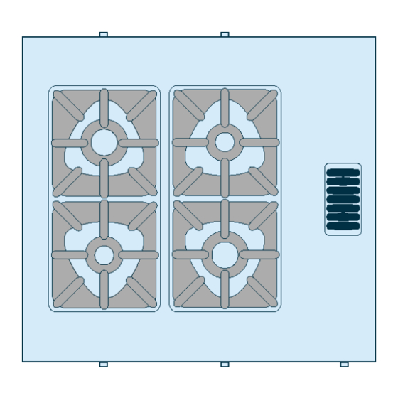
    Hauptorgane A)Kochmulde: aus Edelstahl. B)Kochstellenbrenner: aus emailliertem Gussei- sen, Heizleistung von Größe abhängig C)Wrasenöffnung: für den Austritt des Dampfes aus dem Backofen. D)Piezozündung: zum Zündern der Brenner der Kochmulde und des Backofens. E)Backofen-Schalter: zum Einstellen der Heizlei- stung des Backofens F) Schalter der Kochstellenbrenner: zum Einstel- len der Heizleistung der Kochstellenbrenner G)Backofen mit Thermostat: aus Stahl, mit dich-...
  • Seite 52: Sicherheitshinweise Und Informationen

    SICHERHEITSHINWEISE UND INFORMATIONEN Die Abbildung zeigt die Anordnung der aufgekleb- ten Sicherheitshinweise. A)Typenschild mit Angabe des Herstellers und der Gerätekenndaten. B)Allgemeine Gefahr: Vor Ausführung irgendeines Eingriffs zuerst das Handbuch aufmerksam lesen. C)Allgemeine Gefahr: Beim Waschen des Geräts den Wasserstrahl nicht direkt auf die inneren Tei- le richten.
  • Seite 53: Informationen Zur Sicherheit

    INFORMATIONEN ZUR SICHERHEIT SICHERHEITSVORSCHRIFTEN Der Hersteller hat bei Entwicklung und Fertigung dieses Verluste hervorrufen. Produkts besondere Sorgfalt auf Aspekte verwendet, die Sämtliche Wartungsarbeiten, die präzise Fachkenntnisse eine Gefahr für die Sicherheit und die Gesundheit der Per- oder besondere Fähigkeiten erfordern, dürfen ausschließ- sonen, die dieses Gerät handhaben, hervorrufen können.
  • Seite 54: Beschreibung Der Bedienelemente

    BESCHREIBUNG DER BEDIENELEMENTE Anzeige hinterer Brenner Anzeige Zündflammenbrenner Anzeige Ausschaltung Anzeige vorderer Brenner Temperaturanzeige Anzeige max. Anzeige min. Leistung Leistung IDM-39611400500.tif Das Gerät ist mit Bedienelementen zur Aktivie- schalten des Backofens und zum Regulieren des rung der wichtigsten Funktionen ausgestattet. Backofenbrenners A)Taste der Piezozündung: zum Zünden...
  • Seite 55: Ein- Und Ausschalten Des Backofens

    EIN- UND AUSSCHALTEN DES BACKOFENS Zündung Wichtig Bei der ersten Einschaltung das Gerät rich- tig vorheizen. 1 - Öffnen Sie den Gashahn 2 - Schalter (A) niederdrücken und entgegen dem Uhrzeigersinn drehen (Pos. 1); gleichzeitig die Taste (B) zum Zünden des Zündflammenbren- ners gedrückt halten.
  • Seite 56: Informationen Zur Wartung

    INFORMATIONEN ZUR WARTUNG EMPFEHLUNGEN FÜR DIE WARTUNG Sorgen Sie dafür, dass das Gerät im Zustand maxi- Folgende Elemente sind nach jedem Einsatz und maler Leistungsfähigkeit bleibt, indem Sie die vom bei Bedarf zu reinigen: Hersteller vorgesehenen planmäßigen Wartungs- – die Kochmulde (siehe S. 11); arbeiten ausführen.
  • Seite 57: Reinigung Der Kochmulde, Brenner Und Zubehörteile

    REINIGUNG DER KOCHMULDE, BRENNER UND ZUBEHÖRTEILE Für diesen Vorgang in der angegebenen Weise verfahren. 1 - Brennerdeckel (A) und Brenner (B) ausbauen. 2 - Den Brenner und den Brennerdeckel gründlich rei- nigen und sicherstellen, dass die Löcher des Bren- nerdeckels nicht verstopft sind. 3 - Regelmäßig das Zündloch im Brenner reinigen.
  • Seite 58: Informationen Zu Fehlfunktionen

    INFORMATIONEN ZU FEHLFUNKTIONEN FEHLERSUCHE Vor der Inbetriebnahme wurde das Gerät einem me können vom Benutzer selbst behoben werden; vorläufigen Testlauf unterzogen. Die im Folgenden alle anderen erfordern präzise Fachkenntnisse aufgeführten Informationen sollen Ihnen dabei hel- oder besondere Fähigkeiten und dürfen daher aus- fen, eventuelle Anomalien oder Funktionsstörun- schließlich von qualifiziertem Personal mit nach- gen, die während des Betriebs auftreten können,...
  • Seite 59: Informationen Zur Handhabung Und Zur Installation 7

    INFORMATIONEN ZUR HANDHABUNG UND ZUR INSTALLATION 7 EMPFEHLUNGEN FÜR DIE INSTALLATION UND HANDHABUNG Wichtig Beachten Sie die Hinweise des Herstellers, nen autorisierte Person wird bei Bedarf die direkt auf der Verpackung, auf dem Ge- einen "Sicherheitsplan" aufstellen müssen, rät selbst oder in der Gebrauchsanweisung um die Unversehrtheit der direkt an dem zu finden sind, wenn Sie das Gerät handha- Vorgang beteiligten Personen zu gewähr-...
  • Seite 60: Installation Des Geräts

    INSTALLATION DES GERÄTS Es müssen sämtliche Phasen der Installation, schon von der Umsetzung des allgemeinen Projekts an, be- rücksichtigt werden. Die für diese Operationen autori- sierte Person wird vor Einleitung dieser Phasen den Installationsstandort bestimmen und bei Bedarf einen "Sicherheitsplan" aufstellen, um die Unversehrtheit der direkt am Vorgang beteiligten Personen zu gewährlei- sten und die gesetzlichen Bestimmungen zu befolgen.
  • Seite 61: Nivellieren

    NIVELLIEREN Regulieren Sie die Füße (A), um das Gerät wasser- waagengerecht aufzustellen. IDM-39610800800.tif MONTAGE BEI REIHENAUFSTELLUNG Verfahren Sie folgenderma- ßen, um Geräte (nebeneinan- der) einer Reihe aufzustellen. 1 - Den Schalter (A) abzie- hen. 2 - Die Schrauben (C) aus- schrauben und die Blen- den (B) ausbauen.
  • Seite 62: Gasanschluss

    GASANSCHLUSS Wichtig Diese Arbeit darf nur von zugelassenen und erfahrenen Fachleuten ausgeführt werden. Der Anschluss muss fachgerecht und vor- schriftsmäßig ausgeführt werden und allen einschlägigen gesetzlichen Bestimmungen entsprechen. Nach Ausführung des Anschlus- ses muss vor der Inbetriebnahme des Geräts durch eine allgemeine Kontrolle sichergestellt werden, dass nirgends Gas austritt.
  • Seite 63: Testlauf Zur Abnahme Des Geräts

    TESTLAUF ZUR ABNAHME DES GERÄTS 3 - Sicherstellen, dass die Zündung und die Wich- Wichtig tig Verbrennung bei den Kochstellenbrennern Vor der Inbetriebnahme muss ein Testlauf und beim Backofenbrenner ordnungsgemäß der Anlage durchgeführt werden, um den erfolgen. 4 - Überprüfen Sie Gasdruck und –durchsatz bei mi- Betriebszustand jeder einzelnen Kompo- nimaler und maximaler Zufuhr und regulieren Sie, nente zu überprüfen und eventuelle An-...
  • Seite 64: Einstellung Der Kleinstellung Des Gasventils (Backofen)

    Für diesen Vorgang in der angegebenen Weise verfahren. 1 - Schließen Sie den Gaszufuhrhahn 2 - Den Schalter (A) abziehen. 3 - Die Schrauben (C) ausschrauben und die Blen- den (B) ausbauen. 4 - Die Düse (D) herausziehen und durch die für die verwendete Gasart geeignete Düse erset- zen (siehe die Tabelle am Ende des Hand- buchs).
  • Seite 65: Schmierung Des Gashahns

    EINSTELLUNG DER PRIMÄRLUFT DES KOCHSTELLENBRENNERS (7 KW) Für diesen Vorgang in der angegebenen Weise verfah- ren. 1 - Schließen Sie den Gaszufuhrhahn 2 - Den Schalter (A) abziehen. 3 - Die Schrauben (C) ausschrauben und die Blenden (B) ausbauen. 4 - Die Schraube (D) entfernen. 5 - Die Stellung der Brennerhalterung (E) auf einen Abstand von 20 mm einstellen und die Schraube (D) anziehen.
  • Seite 66: Informationen Zum Austausch

    INFORMATIONEN ZUM AUSTAUSCH HINWEISE ZUM AUSTAUSCH VON TEILEN Vor jedem Eingriff zur Ersetzung eines Teils müs- Ersetzen Sie bei Bedarf Komponenten, die Ver- sen sämtliche vorgesehenen Sicherheitsvorrichtun- schleißerscheinungen zeigen; verwenden Sie da- gen aktiviert werden. Überlegen Sie, ob es bei ausschließlich Originalersatzteile.Es wird jede notwendig ist, das arbeitende Personal und die in Haftung für Personen- oder Komponentenschäden der Nähe befindlichen Personen auf angemessene...
  • Seite 67: Austausch Der Brennerdüse Beim Backofen

    AUSTAUSCH DER BRENNERDÜSE BEIM BACKOFEN Für diesen Vorgang in der angegebenen Weise verfahren. 1 - Schließen Sie den Gaszufuhrhahn 2 - Drehen Sie die Schrauben (B) heraus und montieren Sie die Blende (A) ab. 3 - Schrauben Sie die Düse (C) heraus und erset- zen Sie sie mit dem für den betreffenden Gas- typ geeigneten Ersatzteil (siehe Tabelle am Ende des Handbuches).
  • Seite 68: Austausch Der Luftdüse Des Backofenbrenners

    AUSTAUSCH DER LUFTDÜSE DES BACKOFENBRENNERS Für diesen Vorgang in der angegebenen Weise verfahren. 1 - Schließen Sie den Gaszufuhrhahn 2 - Drehen Sie die Schrauben (B) heraus und montieren Sie die Blende (A) ab. 3 - Die Schraube (C) lockern. 4 - Die Düse (D) herausziehen und durch die für die Gasart geeignete Düse ersetzen (siehe die Tabelle am Ende des Handbuchs).
  • Seite 69: Index Analytique

    INDEX réf. chapitres page 1 INFORMATIONS GENERALES.......... 3 2 INFORMATIONS TECHNIQUES ........4 3 SÉCURITÉ ................7 PARTIE 4 UTILISATION ET FONCTIONNEMENT ......7 5 ENTRETIENS ..............10 6 PANNES ................12 7 MANUTENTION ET INSTALLATION........ 13 8 RÉGLAGES ..............17 PARTIE 9 REMPLACEMENTS DE PIECES........
  • Seite 70 Remplacement de la buse veilleuse Robinet du gaz, graissage, 19 Transport, 13 pilote du brûleur du four, 21 Sécurité et information, signaux de, 6 Utilisation, conseils d’, 9 Remplacement de la buse veilleuse Sécurité, dispositifs de, 5 pilote du brûleur fourneau, 21 Veilleuse pilote du brûleur four- Sécurité, normes de, 7 Remplacement de la douille air du...
  • Seite 71: Informations Generales

    INFORMATIONS GENERALES INFORMATIONS POUR LE LECTEUR Pour retrouver facilement les sujets qui vous in- 2e partie: elle contient toutes les informa- téressent, consulter l’index analytique au début du tions nécessaires aux destinataires homogè- manuel. nes, c’est-à-dire tous les opérateurs experts Ce manuel est divisé...
  • Seite 72: Demande D'assistance

    En fonction des exigences d'utilisation, l'appareil ne de la restauration professionnelle. est réalisé en plusieurs versions (voir figure). L'appareil peut être utilisé sur deux façades ce qui permet de pouvoir l’installer au centre de la pièce. 08WFAAG 12WFAAG IDM-39611400100.tif - 4 - Français...
  • Seite 73: Données Techniques

    Organes principaux A)Plan de travail: en acier inox. B)Brûleurs fourneau: en fonte émaillée, ils peu- vent fournir des puissances variables en fonction de leur dimension. C)Evacuation des fumées: pour évacuer les fu- mées du four. D)Allumage piézoélectrique: pour allumer les brûleurs de table et de four.
  • Seite 74: Accessoires Sur Demande

    SIGNAUX DE SÉCURITÉ ET INFORMATION L’illustration indique la position des signaux appli- qués. A)Plaque d'identification du fabricant et de l'ap- pareil. B)Danger générique: avant tout type d’interven- tion, lire attentivement ce manuel. C)Risque générique: pendant le lavage de l’appa- reil ne pas diriger de jets d’eau sous pression sur les pièces intérieures.
  • Seite 75: Normes De Sécurité

    SÉCURITÉ NORMES DE SÉCURITÉ Le fabricant, lors de la conception et de la fabrica- ce technique précise ou des capacités particulières tion, a fait très attention aux aspects qui peuvent pro- ne peuvent être exécutés que par du personnel voquer des risques à la sécurité et à la santé des qualifié, ayant une expérience reconnue et acquise personnes qui interagissent avec l’appareil.
  • Seite 76: Description Des Commandes

    DESCRIPTION DES COMMANDES Symbole brûleur arrière Index veilleuse pilote Index extinction Symbole brûleur avant Symbole Index puissance Index puissance température maximum minimum IDM-39611400500.tif Sur l’appareil sont disposées les commandes B)Manette de commande du four: pour allumer, pour activer les fonctions principales. éteindre et régler le brûleur du four A)Bouton d’allumage piézoélectrique: pour C)Manette de commande du brûleur fourneau:...
  • Seite 77 ALLUMAGE ET EXTINCTION DU FOUR Allumage Important Au premier allumage, effectuer un pré- chauffage approprié. 1 - Ouvrir le robinet d’alimentation du gaz 2 - Pousser et tourner la manette (A) en sens anti- horaire (pos. 1) et simultanément tenir pressé le bouton (B) pour allumer la veilleuse pilote.
  • Seite 78: Recommandations Pour L'entretien

    ENTRETIENS RECOMMANDATIONS POUR L’ENTRETIEN Maintenir l’appareil en parfait état de fonctionne- Après chaque utilisation et lorsque cela s’avère ment en effectuant les opérations d’entretien pro- nécessaire, nettoyer: grammé prévues par le fabricant. Un bon entretien – La table de cuisson (voir page 11); permettra d’obtenir les meilleures performances, –...
  • Seite 79: Nettoyage Du Four

    NETTOYAGE DE LA TABLE DE CUISSON, DES BRÛLEURS ET DES ACCESSOIRES Pour cette opération, procéder comme suit. 1 - Démonter la tête de brûleur (A) et le brûleur (B). 2 - Nettoyer soigneusement le brûleur et la tête de brû- leur et vérifier que ses trous ne soient pas obstrués.
  • Seite 80 PANNES DÉPANNAGE Avant sa mise en service, l’appareil a été essayé. pour tous les autres il faut une compétence techni- Les informations reportées ci-après ont pour but que précise ou des capacités particulières; ils doi- d’aider à l'identification et à la correction d’éven- vent donc être exécutés exclusivement par du tuels pannes et dysfonctionnements qui pourraient personnel qualifié...
  • Seite 81: Manutention Et Installation

    MANUTENTION ET INSTALLATION RECOMMANDATIONS POUR LA MANUTENTION ET L’INSTALLATION Important Effectuer la manutention et l’installation en effectuer ces opérations devra, si nécessa- respectant les informations fournies par le ire, organiser un “plan de sécurité” pour fabricant, reportées directement sur l’em- sauvegarder la sécurité...
  • Seite 82: Mise En Place De L'appareil

    MISE EN PLACE DE L’APPAREIL Toutes les phases de mise en place doivent être prises en considération, dès la réalisation du projet général. Avant de commencer ces phases, outre la définition de la zone de mise en place, celui qui est autorisé...
  • Seite 83: Mise À Niveau

    MISE À NIVEAU Agir sur les pieds d’appui (A) pour mettre de niveau l’appareil. IDM-39610800800.tif MONTAGE DES APPAREILS EN BATTERIE Pour monter les appareils en batterie (les uns à côté des autres), procéder comme suit. 1 - Enlever la manette (A). 2 - Dévisser les vis (C) et démonter les tableaux de commandes (B).
  • Seite 84: Raccordement Du Gaz

    RACCORDEMENT DU GAZ Important La personne autorisée à effectuer cette opération devra avoir les capacités et l’ex- périence acquise et reconnue dans le sec- teur spécifique ; elle devra effectuer le raccordement dans les règles de l’art et te- nir compte de toutes les exigences impo- sées par les normes et les lois.
  • Seite 85 ESSAI DE L’APPAREIL 3 - Vérifier l’allumage régulier et la combustion des Important brûleurs fourneau et du brûleur du four; Avant la mise en service, l’essai de l’instal- 4 - Vérifier et, si nécessaire, régler la pression et le lation doit être fait pour évaluer les condi- débit du gaz au minimum et au maximum (voir tions opérationnelles...
  • Seite 86 Pour cette opération, procéder comme suit. 1 - Fermer le robinet d’alimentation du gaz 2 - Enlever la manette (A). 3 - Dévisser les vis (C) et démonter les tableaux de commandes (B). 4 - Extraire l’injecteur (D) et le remplacer par celui adapté...
  • Seite 87 RÉGLAGE DE L’AIR PRIMAIRE DU BRÛLEUR FOURNEAU (7KW) Pour cette opération, procéder comme suit. 1 - Fermer le robinet d’alimentation du gaz 2 - Enlever la manette (A). 3 - Dévisser les vis (C) et démonter les tableaux de commandes (B). 4 - Extraire la vis (D).
  • Seite 88: Recommandations Pour Le Remplacement Des Pièces

    REMPLACEMENTS DE PIECESS RECOMMANDATIONS POUR LE REMPLACEMENT DES PIÈCES Avant d’effectuer tout remplacement, activer tous S’il faut remplacer des composants usés, utiliser les dispositifs de sécurité prévus et évaluer s’il faut exclusivement des pièces de rechange d’origine.Le informer les opérateurs travaillant sur l'appareil et fabricant décline toute responsabilité...
  • Seite 89 REMPLACEMENT DE LA BUSE DU BRÛLEUR DU FOUR Pour cette opération, procéder comme suit. 1 - Fermer le robinet d’alimentation du gaz 2 - Dévisser les vis (B) et démonter le tableau de commandes (A). 3 - Dévisser la buse (C) et la remplacer par celle adaptée au type de gaz utilisé...
  • Seite 90: Elimination De L'appareil

    REMPLACEMENT DE LA DOUILLE AIR DU BRÛLEUR DE FOUR Pour cette opération, procéder comme suit. 1 - Fermer le robinet d’alimentation du gaz 2 - Dévisser les vis (B) et démonter le tableau de commandes (A). 3 - Desserrer les vis (C). 4 - Extraire la douille (D) et la remplacer par celle adaptée au type de gaz utilisé...
  • Seite 91 ÍNDICE ref. capítulos pág 1 INFORMACIONES DE CARÁCTER GENERAL ....3 2 INFORMACIONES DE CARÁCTER TÉCNICO ....4 3 INFORMACIONES SOBRE SEGURIDAD ......7 PARTE 4 INFORMACIONES SOBRE EL USO ........7 5 INFORMACIONES SOBRE MANTENIMIENTO ....10 6 INFORMACIONES SOBRE AVERÍAS......12 7 INFORMACIONES SOBRE DESPLAZAMIENTO E INSTALACIÓN ...............
  • Seite 92 Seguridad, dispositivos de, 5 Sustitución inyector testigo piloto Transformación alimentación, 16 Seguridad, normas de, 7 quemador de plano, 21 Transporte, 13 Señalizaciones de seguridad e infor- Sustitución inyector testigo piloto Uso, consejos para el, 9 mación, 6 quemador horno, 21 Sustitución casquillo aire quemador Sustitución piezas, recomendaciones Ventilación del ambiente, 14...
  • Seite 93: Informaciones De Carácter General

    INFORMACIONES DE CARÁCTER GENERAL INFORMACIONES PREVIAS Para ubicar fácilmente los temas específicos de in- 2a parte: contiene todas las informaciones necesarias para destinatarios homogéneos, terés, consúltese el índice analítico que se encuen- esto es, todos los operadores expertos y au- tra al inicio del manual.
  • Seite 94: Informaciones De Carácter Técnico

    (véa- El aparato está equipado con una línea de dos frentes se figura). para permitir su instalación en el centro del local. 08WFAAG 12WFAAG IDM-39611400100.tif - 4 - Español...
  • Seite 95: Datos Técnicos

    Órganos principales A)Encimera: fabricada en acero inox. B)Quemadores de plano: realizados en fundición esmaltada, pueden proporcionar potencias va- riables en función de sus dimensiones C)Salida de humos: para evacuar los humos ge- nerados por el horno. D)Encendido piezoeléctrico: para encender los quemadores de la encimera y del horno.
  • Seite 96: Accesorios Bajo Pedido

    SEÑALIZACIONES DE SEGURIDAD E INFORMACIÓN La ilustración indica la posición de las señalizacio- nes fijadas en el equipo. A)Placa de identificación fabricante y aparato. B)Peligro genérico: antes de efectuar cualquier tipo de intervención léase atentamente el manual. C)Peligro genérico: durante el lavado del aparato no dirigir chorros de agua a presión hacia sus partes internas.
  • Seite 97: Informaciones Sobre Seguridad

    INFORMACIONES SOBRE SEGURIDAD NORMAS DE SEGURIDAD Durante las fases de diseño y producción el fabricante quieren de una competencia técnica precisa o de una ha prestado especial atención a los factores que pue- capacidad especial, deben ser efectuadas exclusiva- den provocar riesgos en cuanto a seguridad y salud de mente por personal calificado y con experiencia reco- las personas que interactúan con el equipo.
  • Seite 98: Descripción De Los Mandos

    DESCRIPCIÓN DE LOS MANDOS Índice quemador trasero Índice testigo piloto Índice apagado Índice quemador delantero Índice temperatura Índice potencia Índice potencia máxima mínima IDM-39611400500.tif Para activar las funciones principales, en el B)Mando de control horno: para encender, apa- equipo se han instalado los siguientes mandos. gar y regular el quemador del horno A)Pulsador de encendido piezoeléctrico: C)Mando de control quemador de plano: para...
  • Seite 99: Encendido Y Apagado Del Horno

    ENCENDIDO Y APAGADO DEL HORNO Encendido Importante Al efectuar el primer encendido se debe acti- var una adecuada fase de precalentamiento. 1 - Abrir el grifo de alimentación del gas 2 - Presionar y hacer girar el mando (A) en sentido an- tihorario (pos.
  • Seite 100: Informaciones Sobre Mantenimiento

    INFORMACIONES SOBRE MANTENIMIENTO RECOMENDACIONES PARA EFECTUAR EL MANTENIMIENTO Mantener el equipo en condiciones de máximo ren- Siempre al final del servicio y cada vez que sea dimiento, efectuando las operaciones de manteni- necesario, limpiar: miento programado previstas por el fabricante. Un –...
  • Seite 101: Control De La Presión Del Gas

    LIMPIEZA DE ENCIMERA, QUEMADORES Y ACCESORIOS Para efectuar esta operación, aplicar las siguientes in- strucciones. 1 - Desmontar el casquete quemador (A) y el quemador (B). 2 - Limpie esmeradamente el quemador y el casquete quemador y verifique que los orificios no estén obstrui- dos.
  • Seite 102: Informaciones Sobre Averías

    INFORMACIONES SOBRE AVERÍAS BÚSQUEDA DE AVERÍAS Antes de la puesta en servicio, el equipo ha sido so- por el usuario, pero otros requieren una competen- metido a prueba de funcionamiento. Las siguientes cia técnica precisa o determinadas capacidades, informaciones tienen por objeto facilitar la identifi- razón por la cual deben ser resueltos exclusiva- cación y corrección de eventuales anomalías y di- mente por personal calificado con experiencia reco-...
  • Seite 103: Informaciones Sobre Desplazamientoe Instalación

    INFORMACIONES SOBRE DESPLAZAMIENTO E INSTALACIÓN RECOMENDACIONES PARA EL DESPLAZAMIENTO Y LA INSTALACIÓN Importante Efectuar el desplazamiento e instalación re- da para efectuar estas operaciones deberá, spetando las indicaciones proporcionadas si fuera necesario, organizar un "plan de por el fabricante, reproducidas directamen- seguridad", a fin de salvaguardar la incolu- te sobre el embalaje, en el equipo y en las midad de las personas directamente invo-...
  • Seite 104: Instalación Del Equipo

    INSTALACIÓN DEL EQUIPO Durante la realización del proyecto general, deben ser consideradas todas las fases de la instalación. Antes de comenzar dichas fases, además de esta- blecer la zona de instalación, la persona autorizada a efectuar estas operaciones deberá, si fuera nece- sario, aplicar un "plan de seguridad"...
  • Seite 105 NIVELACIÓN Operar con las patas de apoyo (A) para nivelar el equipo. IDM-39610800800.tif MONTAJE DE EQUIPOS EN BATERÍA Para montar los equipos en batería (uno al lado del otro) aplicar las siguientes in- strucciones. 1 - Retire el mando (A). 2 - Desenroscar los tornillos (C) y desmontar los pa- neles de mando (B).
  • Seite 106 ENLACE GAS Importante El personal autorizado para ejecutar esta ope- ración debe poseer capacidad y haber adquiri- do experiencia efectiva en el sector específico; la conexión deberá ejecutarse respetando rigu- rosamente todos los requisitos establecidos por las normativas vigentes. Una vez efectuada la conexión, antes de poner en funcionamiento el aparato se deberá...
  • Seite 107: Informaciones Sobre Regulaciones

    PRUEBA DE FUNCIONAMIENTO DEL EQUIPO 3 - Controle el correcto encendido y combustión Importante de los quemadores de plano y del quemador Antes de la puesta en servicio debe efec- del horno. tuarse la prueba de funcionamiento del si- 4 - Controlar y, si fuera necesario, regular la pre- sión y el caudal del gas al mínimo y al máximo stema, a fin de evaluar las condiciones (véase pág.
  • Seite 108 Para efectuar esta operación, aplicar las siguientes instrucciones. 1 - Cerrar el grifo de alimentación del gas 2 - Retire el mando (A). 3 - Desenroscar los tornillos (C) y desmontar los paneles de mando (B). 4 - Extraiga el inyector (D) y cámbielo por otro que sea adecuado para el tipo de gas utilizado (véase tabla al final del manual).
  • Seite 109 REGULACIÓN AIRE PRIMARIO QUEMADOR DE PLANO (7KW) Para efectuar esta operación, aplicar las siguientes in- strucciones. 1 - Cerrar el grifo de alimentación del gas 2 - Retire el mando (A). 3 - Desenroscar los tornillos (C) y desmontar los pa- neles de mando (B).
  • Seite 110: Informaciones Sobre Sustituciones

    INFORMACIONES SOBRE SUSTITUCIONES RECOMENDACIONES PARA EFECTUAR LA SUSTITUCIÓN DE LAS PIEZAS Antes de efectuar cualquiera operación de sustitu- Para sustituir componentes desgastados se debe- ción, activar todos los dispositivos de seguridad rán utilizar exclusivamente piezas de recambio ori- previstos y evaluar la conveniencia de informar ginales.
  • Seite 111 SUSTITUCIÓN INYECTOR DEL QUEMADOR HORNO Para efectuar esta operación, aplicar las siguientes instrucciones. 1 - Cerrar el grifo de alimentación del gas 2 - Desenroscar los tornillos (B) y desmontar el ta- blero de instrumentos (A). 3 - Desenrosque el inyector (C) y cámbielo por otro que sea adecuado para el tipo de gas utili- zado (véase tabla al final del manual).
  • Seite 112 SUSTITUCIÓN CASQUILLO AIRE QUEMADOR HORNO Para efectuar esta operación, aplicar las siguientes instrucciones. 1 - Cerrar el grifo de alimentación del gas 2 - Desenroscar los tornillos (B) y desmontar el ta- blero de instrumentos (A). 3 - Afloje el tornillo (C). 4 - Extraiga el casquillo (D) y cámbielo por otro que sea adecuado para el tipo de gas utilizado (véase tabla al final del manual).
  • Seite 113: Anexos

    ø130 - 10kW 10kW Modelo Conexión eléctrica (Min. 2,3kW) (Min. 2,5/3,2kW) (Min. 4kW) 0,6W/230 V1~ N 08WFAAG N. 1 N. 1 N. 1 27 2,86 m /h 3,32 m /h 2,13 Kg/h 2,1Kg/h 50/60Hz SCHEDA ALLACCIAMENTI - CONNECTION CARD - ANSCHLUSSSCHEMA FICHE DES RACCORDEMENTS - FICHA DE ENLACES IDM-39611401400.tif...
  • Seite 114 Bruciatori di piano - Top burners Bruciatori di forno - Oven bur- Consumo gas - Gas consumption Modello Allacciamento elettrico Kochstellenbrenner - ners Backofenbrenner - Brû- Gasverbrauch - Consommation de gaz Model Electrical connection Brûleurs fourneau - leurs de four - Quemadores Consumo de gas Modelle Stromanschluss...
  • Seite 115 SYSTEM DIAGRAM - ELEKTRISCHER SCHALTPLAN PIEZOZÜNDUNG - SCHÉMA ÉLECTRIQUE ALLUMAGE PIÉZOÉLECTRIQUE - ESQUEMA ELÉCTRICO PIEZOELÉCTRICO ENCENDIDO 08WFAAG IDM-39611401700.tif 1) Morsettiera - Terminal board - Klemmenbrett - Plaque à bornes - Regleta de 4) Candeletta anteriore - Front plug - Vordere Zündkerze - Bougie avant - Bujía conexión...
  • Seite 116 Tabella iniettori bruciatore di piano ø110 - Table of top burner injectors ø110 - Tabelle: Düsen für Kochstellenbrenner ø110 Tableau des injecteurs du brûleur fourneau ø110 - Tabla inyectores quemador de plano ø110 p (3) mbar ø (4) ø (5) ø...
  • Seite 117 Tabella iniettori bruciatore di piano ø110 - Table of top burner injectors ø110 - Tabelle: Düsen für Kochstellenbrenner ø110 Tableau des injecteurs du brûleur fourneau ø110 - Tabla inyectores quemador de plano ø110 ø (4) ø (5) ø (6) ø (8) p (3) mbar p (7) mbar Pen mbar Qn max kW...
  • Seite 118 Tabella iniettori bruciatore di piano ø130 - Table of top burner injectors ø130 - Tabelle: Düsen für Kochstellenbrenner ø130 Tableau des injecteurs du brûleur fourneau ø130 - Tabla inyectores quemador de plano ø130 P (3) ø (4) ø (5) ø (6) P (7) ø...
  • Seite 119 Tabella iniettori bruciatore di piano ø130 - Table of top burner injectors ø130 - Tabelle: Düsen für Kochstellenbrenner ø130 Tableau des injecteurs du brûleur fourneau ø130 - Tabla inyectores quemador de plano ø130 P (3) ø (4) ø (5) ø (6) P (7) ø...
  • Seite 120 Tabella iniettori bruciatore Forno - Table of oven burner injectors - Tabelle: Düsen für Backofenbrenner Tableau des injecteurs du brûleur du four - Tabla inyectores quemador horno P (3) mbar ø (4) ø (5) ø (6) ø (8) P (7) mbar Pen mbar Qn max kW Qn min kW G30/G31...
  • Seite 121 Tabella iniettori bruciatore Forno - Table of oven burner injectors - Tabelle: Düsen für Backofenbrenner Tableau des injecteurs du brûleur du four - Tabla inyectores quemador horno G30/G31 SE II2H3B/P G30/G31 SI II2H3B/P (1) Paese - Land - Country - Pays - Pais (6) Boccola aria - Bchse - Bushing - Bague - Casquillo (2) Categoria - Kategorie - Category - Categorie - Categoria (7) Pressione ugello bruciatore al minimo - Druck Brennerduse der Kleinstell-...
  • Seite 122 Tabella caratteristiche gas - Table of gas characteristics - Tabelle der Gas-Eigenschaften Tableau des caractéristiques du gaz - Tabla características gas Potere calorifero inferiore (Hi) Famiglia Tipo di gas Indice Wobbe (MJ/m Net calorific value (Hi) Group Gas type Wobbe index (MJ/m Unterer Heizwert (Hi) Familie Gastypen...

Diese Anleitung auch für:

12wfaag

Inhaltsverzeichnis