Herunterladen Inhalt Inhalt Diese Seite drucken
Fronius LaserHybrid Bedienungsanleitung
Vorschau ausblenden Andere Handbücher für LaserHybrid:
Inhaltsverzeichnis

Werbung

Verfügbare Sprachen

Verfügbare Sprachen

/ Perfect Charging /
Perfect Welding
LaserHybrid-Kopf
LaserHybrid welding head
Tête de soudage laser hybride
42,0410,0844
/ Solar Energy
003-24092018
Bedienungsanleitung
Ersatzteilliste
LaserHybrid
Operating Instructions
Spare parts list
LaserHybrid
Instructions de service
Liste des pièces de rechange
LaserHybrid

Werbung

Inhaltsverzeichnis
loading

Inhaltszusammenfassung für Fronius LaserHybrid

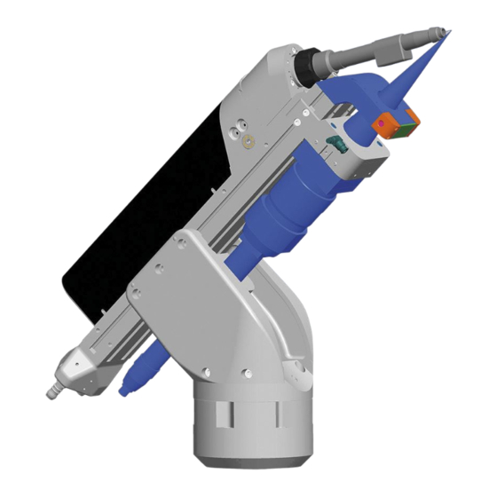
  • Seite 1 / Perfect Charging / Perfect Welding / Solar Energy Bedienungsanleitung LaserHybrid-Kopf Ersatzteilliste LaserHybrid Operating Instructions LaserHybrid welding head Spare parts list LaserHybrid Instructions de service Tête de soudage laser hybride Liste des pièces de rechange LaserHybrid 42,0410,0844 003-24092018...
  • Seite 3: Einleitung

    Fronius Produkt. Die vorliegende Anleitung hilft Ihnen, sich mit diesem vertraut zu machen. Indem Sie die Anleitung sorgfältig lesen, lernen Sie die viel- fältigen Möglichkeiten Ihres Fronius Produktes kennen. Nur so können Sie seine Vorteile bestmöglich nutzen. Bitte beachten Sie auch die Sicherheitsvorschriften und sorgen Sie so für mehr Sicherheit am Einsatzort des Produktes.
  • Seite 5: Inhaltsverzeichnis

    Fokus-Punkt einstellen - Übersicht ....................... Fokus-Punkt einstellen - vorbereitende Tätigkeiten................Fokus-Punkt in der z-Achse einstellen....................Fokus-Punkt in der x- und y-Achse einstellen - Vorbereitung............... Fokus-Punkt in der x- und y-Achse einstellen..................x/y-Richtung: Nachbereitung......................... Signalablauf für das LaserHybrid-Schweißen .................... Sicherheit .............................. Signalablauf für das LaserHybrid-Schweißen..................
  • Seite 6 Allgemeines ............................Spritzerschutz reinigen / austauschen ....................Schutzglas reinigen / austauschen ....................... LaserHybrid-Schlauchpaket austauschen .................... Technische Daten ............................LaserHybrid-Kopf ..........................LaserHybrid Ultracompact Schlauchpaket.................... Gesamtschaltplan ............................Schaltplan ............................. Schaltplan Druckschalter ........................... Schaltplan ............................. Spare parts list: LaserHybrid welding head ....................158...
  • Seite 7: Sicherheitsvorschriften

    Den LaserHybrid-Kopf oder die verwendete Stromquelle nie zum Auftauen von Rohren verwenden. Der LaserHybrid-Kopf ist für den Betrieb in Industrie und Gewerbe ausgelegt. Für Schä- den, die auf den Einsatz im Wohnbereich zurückzuführen sind, haftet der Hersteller nicht. Für mangelhafte oder fehlerhafte Arbeitsergebnisse übernimmt der Hersteller ebenfalls keine Haftung.
  • Seite 8: Verpflichtungen Des Betreibers

    Umgebungsluft: frei von Staub, Säuren, korrosiven Gasen oder Substanzen, usw. Höhenlage über dem Meeresspiegel: bis 2000 m (6561 ft. 8.16 in.) Verpflichtungen Der Betreiber verpflichtet sich, nur Personen am LaserHybrid-Kopf arbeiten zu lassen, die des Betreibers mit den grundlegenden Vorschriften über Arbeitssicherheit und Unfallverhütung ver- traut und in die Handhabung des LaserHybrid-Kopf eingewiesen sind diese Bedienungsanleitung, insbesondere das Kapitel „Sicherheitsvorschriften“...
  • Seite 9: Gefahr Durch Funkenflug

    Funkenflug kann Brände und Explosionen auslösen. Funkenflug Niemals in der Nähe brennbarer Materialien schweißen. Brennbare Materialien müssen mindestens 11 m (35 ft.) vom LaserHybrid-Schweißpro- zess entfernt sein oder mit einer geprüften Abdeckung zugedeckt werden. Geeigneten, geprüften Feuerlöscher bereithalten. Funken und heiße Metallteile können auch durch kleine Ritzen und Öffnungen in umliegen- de Bereiche gelangen.
  • Seite 10: Vagabundierende Schweißströme

    Sämtliche Kabel und Leitungen müssen fest, unbeschädigt, isoliert und ausreichend di- mensioniert sein. Lose Verbindungen, angeschmorte, beschädigte oder unterdimensio- nierte Kabel und Leitungen sofort erneuern. Vor jedem Gebrauch die Stromverbindungen durch Handgriff auf festen Sitz überprüfen. Bei Stromkabeln mit Bajonettstecker das Stromkabel um min. 180° um die Längsachse verdrehen und vorspannen.
  • Seite 11: Emv-Maßnahmen

    EMV-Maßnahmen Warnung vor elektromagnetischem Feld! Elektromagnetische Felder können Gesund- heitsschäden verursachen, die noch nicht bekannt sind. Es liegt im Verantwortungsbereich des Betreibers dafür Sorge zu tragen, dass keine elek- tromagnetischen Störungen an elektrischen und elektronischen Einrichtungen auftreten. Werden elektromagnetische Störungen festgestellt, ist der Betreiber verpflichtet, Maßnah- men für die Störungsbehebung zu ergreifen.
  • Seite 12: Informelle Sicherheitsmaßnahmen

    Adapters für den Schutzgas-Anschluss. Das geräteseitige Gewinde des Adap- ters, für den Schutzgas-Anschluss, vor der Montage mittels geeignetem Teflon-Band abdichten. Informelle Sicher- Die Bedienungsanleitung ist ständig am Einsatzort des LaserHybrid-Kopfes aufzubewah- heitsmaßnahmen ren. Ergänzend zur Bedienungsanleitung sind die allgemein gültigen sowie die örtlichen Re-...
  • Seite 13: Sicherheitsmaßnahmen Am Aufstellort

    Alle Sicherheits- und Gefahrenhinweise am LaserHybrid-Kopf sind in lesbarem Zustand zu halten. Sicherheitsmaß- Die Zelle für den LaserHybrid-Schweißprozess muss folgende Anforderungen erfüllen: nahmen am Auf- lichtdicht gegenüber umliegenden Räumen abgeschlossen stellort mit mindestens 1 mm Stahlblech und/oder zugelassenem Laser-Schutzglas vor Aus- tritt von UV- und Laserstrahlen abgeschirmt Sowohl der Laser-Schweißprozess, als auch der Lichtbogen-Schweißprozess, muss...
  • Seite 14: Vorschrift

    Stromquellen forderlich. Der Hersteller empfiehlt ein Kalibrierintervall von 12 Monaten. Setzen Sie sich für nähere Informationen mit Ihrer Servicestelle in Verbindung. Die CE-Kenn- Der LaserHybrid-Kopf erfüllt die grundlegenden Anforderungen der Niederspannungs-und zeichnung Elektromagnetischen Verträglichkeits-Richtlinie und ist daher CE-gekennzeichnet. Urheberrecht Das Urheberrecht an dieser Bedienungsanleitung verbleibt beim Hersteller.
  • Seite 15: Allgemeines

    Verhältnis zur Breite große Schweißnaht-Tiefe. Die Energieflussdichte des Lichtbogenpro- zesses beträgt ungefähr 104 W/cm². In der folgenden Abbildung ist das Prinzip des LaserHybrid-Schweißens skizziert. Der dar- gestellte Laserstrahl führt dem Schweißgut im oberen Nahtbereich zusätzlich zum Licht- bogen Wärme zu. Im Gegensatz zu einer losen Kombination des Laserschweißverfahrens mit dem Lichtbogenprozess gilt das Hybridschweißen als Bündelung beider Verfahren in-...
  • Seite 16: Synergien

    Synergien Aus der Zusammenführung des Laserprozesses mit dem Lichtbogenverfahren können fol- gende Synergieeffekte erschlossen werden: Vorteile des LaserHybrid Verfahrens gegenüber dem Laserprozess allein: Schweißbarkeit von Bauteilen mit weiteren Spaltabständen, infolge des größeren Schmelzbades höhere Spaltüberbrückbarkeit bei kurzzeitig auftretendem Spalt breiterer und tieferer Einbrand wesentlich höheres Anwendungsgebiet...
  • Seite 17 Das gegenüber dem Lichtbogen-Verfahren kleinere Schmelzbad schränkt die Wärmeein- bringung ein und ermöglicht dadurch eine kleinere Wärmeeinflusszone. Die Folge ist ge- ringerer Verzug, wodurch sich der Aufwand für Nacharbeiten verringert. Der Lichtbogenprozess sorgt für nachträgliche Wärmeeinbringung. Diese sorgt für den zusätz- lichen Effekt des Anlassens des bereits vom Laser geschweißten Werkstück-Bereiches.
  • Seite 18: Führung Des Laserhybrid-Kopfes

    Führung des LaserHybrid-Kopfes Ausrichtung Den LaserHybrid-Kopf stets in einem An- stellwinkel von „5° stechend“ führen. Das heißt, der LaserHybrid-Kopf verfährt um 5° geneigt in y-Richtung. 5° HINWEIS! Wird die Ausrichtung „5° stechend“ nicht beachtet, kommt es zu schwerwiegenden Schäden an der Lichtleitfaser, da die Laserstrahlung unmittelbar in die Laser-Optik reflektiert wird.
  • Seite 19: Einstellen Der Relativen Position Lichtbogen / Laser

    Einstellen der relativen Position Lichtbogen / Laser Sicherheit WARNUNG! Fehlerhaft durchgeführte Arbeiten können schwerwiegende Perso- nen- und Sachschäden verursachen. Die Einstellarbeiten dürfen nur von geschul- tem Fachpersonal durchgeführt werden! Beachten Sie die Sicherheitsvorschriften in der Bedienungsanleitung, insbesondere den Teil „Si- cherheitstechnische Inspektion“.
  • Seite 20: Fixierschrauben

    Fixierschrauben HINWEIS! Die Abbildung zeigt den LaserHybrid-Kopf ohne Gehäusedeckel. Vor jeder Inbetriebnahme des LaserHybrid-Kopfes, den Gehäusedeckel montie- ren. Fixierschrauben für Koordinatenachsen...
  • Seite 21: X-Achse Einrichten

    Einstellbereich ... +/- 2 mm Fixierschrauben (2) festziehen (Abbildung Fixierschrauben für Koordinatenachsen) Gehäusedeckel montieren y-Achse einrich- Lageänderung in y-Richtung einstellen Lageänderung in y-Richtung ablesen Am LaserHybrid-Kopf Gehäusedeckel abmontieren Fixierschrauben (3) lösen (Abbildung Fixierschrauben für Koordinatenachsen) Gewünschte Lageänderung mittels Einstellschraube gemäß Abbildung...
  • Seite 22: Z-Achse Einrichten

    (Abbildung Fixierschrauben für Koordinatenachsen) Gehäusedeckel montieren z-Achse einrich- Lageänderung in z-Richtung einstellen Lageänderung in z-Richtung ablesen Am LaserHybrid-Kopf Gehäusedeckel abmontieren Fixierschrauben (1) und (2) lösen (Abbildung Fixierschrauben für Koordinatenachsen) Gewünschte Lageänderung mittels Einstellschraube gemäß Abbildung Eine Viertel Drehung entspricht 0,25 mm Einstellweg.
  • Seite 23: Kollisionsschutz

    Auslenkung des Schweißbrenners öffnet der Stromkreis (Ringleitung) zwischen den beiden Eingängen für die Robotersteuerung. Die Ringleitung führt vom Print LBDSP am LaserHybrid-Kopf über die Schlauchpakete und den Zwischenantrieb bis zum Anschluss des verwendeten Roboterinterfaces oder Feld- busses an der Stromquelle.
  • Seite 24: Einstellen Der Position An Der Aufnahmeeinheit Für Den Roboter

    Fachpersonal durchgeführt werden! Beachten Sie die Sicherheitsvorschriften in der Bedienungsanleitung, insbesondere den Teil „Si- cherheitstechnische Inspektion“. Allgemeines Eine Montage des LaserHybrid-Kopfes an der Aufnahmeeinheit für den Roboter ist in den nachfolgend illustrierten Positionen A bis D möglich. Position A 180°...
  • Seite 25: Position B

    Position B 180° Montage des LaserHybrid-Kopfes in Position B (alternativ um 180° gedreht) Aufnahmeeinheit HINWEIS! In den Positionen A und B kann der Laser-Hybrid-Kopf um 180° ge- dreht montiert werden. Diese Einstellung dient zur erleichterten Ausführung kur- zer Schweißnähte an Randzonen oder in Ecken des Werkstückes.
  • Seite 26: Position C Und D

    Position C und D Position C Position D Montage des LaserHybrid-Kopfes in Position C und D Aufnahmeeinheit...
  • Seite 27: Fokus-Punkt Einstellen

    Fokus-Punkt einstellen Sicherheit WARNUNG! Fehlerhaft durchgeführte Arbeiten können schwerwiegende Perso- nen- und Sachschäden verursachen. Die Einstellarbeiten dürfen nur von geschul- tem Fachpersonal durchgeführt werden! Beachten Sie die Sicherheitsvorschriften in der Bedienungsanleitung, insbesondere den Teil „Si- cherheitstechnische Inspektion“. Allgemeines Für die beschriebenen Einstellarbeiten ist ein Pilot-Laser mit geringer Leistung erforder- lich.
  • Seite 28: Fokus-Punkt In Der Z-Achse Einstellen

    Justierring an der Laser-Optik auf „0“ einstellen WARNUNG! Verletzungsgefahr durch aktiven Laser. Bei der Bestimmung des Fokus-Punktes gelten dieselben Schutzbestimmungen wie beim LaserHybrid- Schweißen (z.B.: Schutz der Augen mittels vorschriftsgemäßem Filtereinsatz für Laser-Schutzklasse 4, etc.). Die Sicherheitsvorschriften in dieser Bedienungsan-...
  • Seite 29: Fokus-Punkt In Der X- Und Y-Achse Einstellen - Vorbereitung

    Fokus-Punkt in Im Lieferumfang des Laser-Schweißkopfes ist eine Metallschablone (1) zur exakten Ein- der x- und y-Ach- stellung der Position des Fokus-Punktes gegenüber dem Ende der Drahtelektrode enthal- se einstellen - ten. Vorbereitung Am Schweißbrenner des Laser- Schweißkopfes einen Stick-Out von 14 mm einstellen Referenzpunkt des Roboters anfahren Befindet sich der Fokus des Pilot-Lasers im...
  • Seite 30: Fokus-Punkt In Der X- Und Y-Achse Einstellen

    HINWEIS! Gefahr des Auseinan- derfallens von Teilen. Die vier Be- festigungsschrauben nur soweit lösen, dass noch kein erkennba- res Spiel entsteht und die Teile noch spürbar stramm aneinander- gefügt sind. An der Optik-Halterung vier Befesti- gungsschrauben SW 5 mm (7) etwas lösen HINWEIS! Gefahr des Auseinan- derfallens von Teilen.
  • Seite 31 Lageänderung Laserstrahl / Lichtbogenprozess Fokus-Punkt in positiver x-Richtung ein- stellen Schrauben (9) um 2 Umdrehungen lö- Schrauben (10) justieren Schrauben (9) festschrauben (10) Positive x-Richtung Fokus-Punkt in negativer x-Richtung einstellen Schrauben (9) justieren Schrauben (10) um 2 Umdrehungen lösen Schrauben (10) festschrauben (10) Negative x-Richtung...
  • Seite 32: X/Y-Richtung: Nachbereitung

    Fokus-Punkt in y-Richtung einstellen Schrauben (9) ca. 1/4 Umdrehung lö- Schrauben (11) justieren Schrauben (9) festschrauben (11) y-Richtung x/y-Richtung: Die Nachbereitung des Einstellvorganges erfolgt in umgekehrter Reihenfolge zu den Ar- Nachbereitung beitschritten im Abschnitt „Vorbereitung“.
  • Seite 33: Signalablauf Für Das Laserhybrid-Schweißen

    Betriebsbit „2“ auf „0“ setzen Ist die Betriebsart „Job“ angewählt, finden Sie nähere Informationen zum Jobbetrieb in der Bedienungsanleitung der MIG/MAG-Stromquelle. Ist ein Vorwärmen nicht erforderlich, bei „Startposition LaserHybrid-Schweißen“ fort- setzen. Startposition Vorwärmen: Voraussetzung: Der Laser muss zur Strahlfreigabe bereit sein.
  • Seite 34: Startposition Laserhybrid-Schweißen

    Startposition LaserHybrid-Schweißen: Voraussetzung: Der Laser muss zur Strahlfreigabe bereit sein. Signal „Lichtbogen ein“ setzen Warten auf das Stromfluss-Signal („Lichtbogen steht“) Signal „Laser ein“ setzen Signal „Roboter Start“ setzen Der Abstand zwischen Laser und Drahtelektrode soll je nach Prozess 1 - 5 mm betra- gen.
  • Seite 35: Laser-Heißdrahtlöten Ohne Rcu 5000I

    Laser-Heißdrahtlöten ohne RCU 5000i A: Löten Start Für ein gutes Ausfließen der Lötverbindung an die Nahtflanken folgendes beachten: Fokus-Durchmesser = Drahtdurchmesser + 30 % Brenneranstellung ist 35° schleppend „Gas Test“ setzen Betriebsart 5 „CC / CV“ anwählen Betriebsbit „0“ auf „1“ setzen Betriebsbit „1“...
  • Seite 36: Laser-Heißdrahtlöten Mit Rcu 5000I

    Laser-Heißdrahtlöten mit RCU 5000i A: Löten Start Für ein gutes Ausfließen der Lötverbindung an die Nahtflanken folgendes beachten: Fokus-Durchmesser = Drahtdurchmesser + 30 % Brenneranstellung ist 35° schleppend „Gas Test“ setzen Betriebsart 3 „interne Parameteran- wahl“ anwählen Betriebsbit „0“ auf „1“ setzen Betriebsbit „1“...
  • Seite 37: Drahtantrieb Montieren

    Drahtantrieb montieren Sicherheit WARNUNG! Fehlerhaft durchgeführte Arbeiten können schwerwiegende Perso- nen- und Sachschäden verursachen. Die Einstellarbeiten dürfen nur von geschul- tem Fachpersonal durchgeführt werden! Beachten Sie die Sicherheitsvorschriften in der Bedienungsanleitung, insbesondere den Teil „Si- cherheitstechnische Inspektion“. Lieferumfang Die Lieferung für den Drahtantrieb ist für die Schweißdraht-Durchmesser 1,0 mm, 1,2 mm und 1,6 mm verfügbar.
  • Seite 38 HINWEIS! Keine der hier angeführten Drahtförder-Komponenten durch davon abweichende Ausführungen ersetzen. Insbesondere bei Verwendung anderer als der angegebenen V-Nut Rollen kann es zu schwerwiegenden Problemen bei der Drahtförderung kommen. Mit dem LaserHybrid-Kopf mitgeliefertes Werkzeug: Pos. Bezeichnung Stück Gabelschlüssel, SW 8/10 mm 42,0410,0004 Triebradschlüssel...
  • Seite 39: Weiteres Zubehör

    Weiteres Zubehör Verbindungs- LaserHybrid- Laser Stromquelle Drahtvorschub Schlauchpaket Schlauchpaket Hybrid-Kopf TPS 4000 4,047,292 VR 1500 K/4R/ intern 4,075,100 W/F++ 4,047,332 + Optionen 4,045,848,000 + Optionen extern 4,047,452 Förderrolle aus- bauen Deckel am Drahtantrieb abmontieren Draht ausfädeln Klemmbügel (A) und Schwenkhebel (B) aufschwenken „Sperrzahn-Mutter“...
  • Seite 40: Förderrolle Einbauen

    Förderrolle ein- bauen „Triebrad Motor“ (D) aufsetzen „Förderrolle“ (2) aufsetzen „Sperrzahn-Mutter“ (C) ansetzen „Sperrzahn-Mutter“ (C) mit Gabelschlüssel (6) und Triebradschlüssel (7) festziehen Klemmbügel (A) und Schwenkhebel (B) zuschwenken Draht einfädeln Draht-Führungs- (1) (3) seele des Bren- ners aus- und einbauen Draht-Führungsseele des Brenners ausbauen Draht ausfädeln Rändelmutter (G) von Hand lösen...
  • Seite 41: Draht-Führungsseele Intern Des Schlauchpakets Aus- Und Einbauen

    Draht-Führungs- WICHTIG! Ist anstelle der Draht-Führungsseele intern die Draht-Führungsseele extern seele intern des vorhanden, gilt der Abschnitt „Draht-Führungsseele extern des Schlauchpakets aus- und Schlauchpakets einbauen“. aus- und einbau- Draht-Führungsseele intern des Schlauchpakets ausbauen Draht ausfädeln Sechskantmutter (H) mittels Gabelschlüssel - SW 10 - (6) lösen Draht-Führungsseele (I) herausziehen Draht-Führungsseele intern des Schlauchpakets einbauen HINWEIS! Die Draht-Führungsseele (I) darf weder Förderrolle (2) noch Druckrol-...
  • Seite 42: Draht-Führungsseele Extern Des Schlauchpakets Einbauen

    Draht-Führungs- WICHTIG! Ist anstelle der Draht-Führungsseele extern die Draht-Führungsseele intern seele extern des vorhanden, gilt der Abschnitt „Draht-Führungsseele intern des Schlauchpakets ausbauen“. Schlauchpakets einbauen Draht-Führungsseele extern einbauen Draht-Führungsseele extern einbauen WICHTIG! Beim Einschieben des Draht-Förderschlauchs (M) darauf achten, dass der Teil (P) voran zeigt.
  • Seite 43 Brenner montieren HINWEIS! Beim Aufsetzen des Brenners (J) auf die Kuppelstelle des LaserHyb- rid-Kopfes folgendes beachten: Die Draht-Führungsseele (1) muss knickfrei in die Bohrung an der Kuppelstelle eintreten. Brenner (J) auf die Kuppelstelle aufsetzen Überwurfmutter (K) mit dem Brennerschlüssel (8) festziehen Deckel am Drahtantrieb montieren...
  • Seite 44: Anschluss-Spezifikationen

    LaserHybrid-Kopf darf nur ein Trumpf-Laser mit entsprechendem Lichtleiter und Kühlgerät für die Optik angeschlossen werden. Die Brennweite für die Trumpf-Optik be- trägt F = 220 mm. Optional wird der LaserHybrid-Kopf mit einer Rofin-Sinar-Optik (Brennweite F > 220 mm) angeboten. Für den Lichtbogen-Prozess sind zwei Konfigurationen vorgesehen:...
  • Seite 45: Anschluss-Spezifikationen

    Anschließen eines Schlauches gemäß folgender Daten: Innendurchmesser Di = 51 mm Außendurchmesser Da = 57 mm max. Länge = 10 m Metallische Verstärkungen: d = 2 - 5 mm h = ca. 5 mm LaserHybrid-Schlauchpaket für Zwischenantrieb VR 1500 F++...
  • Seite 46: Bezeichnung

    Pos. Bezeichnung 37-poliger CPC-Stecker für Steuerleitungen von: Drahtantrieb Abschaltbox LocalNet Anschluss-Spezifikation Zweiter Schlauch gegenüberliegend Atmospärischer Überdruck im Strömungszustand: = 2,5 bar an beiden Anschlüssen gesamt = 1460 l/min Innendurchmesser Di = 12 mm HINWEIS! Brenner und Gasdüse werden vom Kühlgerät der Schweiß-Strom- quelle mitgekühlt.
  • Seite 47: Betrieb - Spezifikationen

    Roboter müssen folgende Anforderungen an den Roboter erfüllt sein: Die Masse des LaserHybrid-Kopfes beträgt ca. 19 kg. Die Optik wiegt zusätzlich ca. 3 kg. Für den komplett mit Optik und Schlauchpaket ausgerüsteten LaserHybrid-Kopf ist eine Masse von ca. 30 kg einzukalkulieren.
  • Seite 48: Pflege- Und Wartungsmaßnahmen

    Pflege- und Wartungsmaßnahmen Allgemeines HINWEIS! Kommt es häufig zur Verschmutzung des Spritzerschutzes und des Schutzglases infolge Schweißrauches, empfehlen wir die Verwendung der zu- sätzlichen Absaugung. Nähere Informationen zum Anschluss der zusätzlichen Absaugung entnehmen Sie bitte dem Kapitel „Anschluss-Spezifikationen“. Spritzerschutz Der Spritzerschutz befindet sich unterhalb des Schutzglases für die Laser-Optik und reinigen / austau- schützt gegen vorzeitige Verschmutzung.
  • Seite 49: Laserhybrid-Schlauchpaket Austauschen

    LasetrHybrid-Schlauchpaketes austauschen den LaserHybrid-Kopf gemäß Ab- bildung neigen, sodass sich der Brenner (4) oberhalb des An- schlusses (5) für das LaserHybrid- Schlauchpaket befindet. Erklärung: Befindet sich noch Kühlmittel im Schlauch- paket, würde dieses in den Brenner gelan- gen und den Bereich der Gasdüse und des...
  • Seite 50: Technische Daten

    Abmessungen 769,5 x 159 x 415,7 mm Max. Laser-Leistung am Werkstück 4000 W Max. Strombelastbarkeit (100 % ED) 250 A LaserHybrid Ul- Max. Schweißstrom bei 100 % ED (10 min / 40 °C) tracompact M21 (EN439) 350 A Schlauchpaket C1 (EN439)
  • Seite 51: Gesamtschaltplan

    Gesamtschaltplan Schaltplan...
  • Seite 52: Schaltplan Druckschalter

    Schaltplan Druckschalter Schaltplan Druckschalter S1 / S2: > 2,5 bar (36.25 psi.) < 2,0 bar (29 psi.) Die externe Steuerung liefert 24 V für S1 und S2, in Serie geschaltet. Die Signalauswertung erfolgt durch einen externen System-Input.
  • Seite 53 Thank you for the trust you have placed in our company and congratulations on buying this high-quality Fronius product. These instructions will help you familiarise yourself with the product. Reading the instructions carefully will enable you to learn about the many different features it has to offer.
  • Seite 55 General ..............................Basic principle............................Mode of operation and practical application ..................LaserHybrid process ..........................Synergies .............................. Summary............................... Guiding the LaserHybrid head ........................Alignment .............................. Setting the relative position of the arc/laser ....................Safety..............................Stick out ..............................Fixing screws ............................Adjusting the x-axis..........................
  • Seite 56 Cleaning/replacing the protective glass ....................Replacing the LaserHybrid hosepack ....................Technical data............................LaserHybrid head..........................LaserHybrid Ultracompact hosepack ....................Entire circuit diagram ..........................100 Circuit diagram............................100 Pressure switch circuit diagram ......................... 101 Circuit diagram............................101 Spare parts list: LaserHybrid welding head ....................158...
  • Seite 57: Safety Rules

    For the location of the safety and danger notices on the LaserHybrid head, refer to the "General" section in the operating instructions for your LaserHybrid head. Before switching on the device, rectify any faults that could compromise safety.
  • Seite 58: Obligations Of The Operator

    (120 dbA) If other persons are in the closed cell for the LaserHybrid process, you must: make them aware of all the dangers that may occur during operation (e.g. risk of a build-up of gases that are detrimental to health, possible risk of suffocation due to lack of oxygen in the air, danger from laser light, etc.)
  • Seite 59: Danger From Flying Sparks

    Never weld close to flammable materials. Flammable materials must be at least 11 m (35 ft.) away from the LaserHybrid welding pro- cess, or alternatively covered with an approved cover. A suitable, tested fire extinguisher must be available and ready for use.
  • Seite 60: Meandering Welding Currents

    The electrode (rod electrode, tungsten electrode, welding wire, etc.) must never be immersed in liquid for cooling Never touch the electrode when the power source is switched on. Double the open circuit voltage of a power source can occur between the welding elec- trodes of two power sources.
  • Seite 61: Specific Hazards

    Check for possible problems, and check and evaluate neighbouring devices' resistance to interference according to national and international requirements: Safety devices Power, signal and data transfer lines IT and telecommunications devices Measuring and calibrating devices The health of persons in the vicinity, e.g. users of pacemakers and hearing aids Individuals with pacemakers must seek advice from their doctor before approaching the welding work area.
  • Seite 62: Informal Safety Measures

    In addition to the operating instructions, any generally applicable and local regulations re- garding accident prevention and environmental protection must be provided and followed. All safety and danger notices on the LaserHybrid head must be kept in a legible condition. Safety measures...
  • Seite 63: Safety Measures In Normal Operation

    Never bypass or disable safety devices. Before starting up the LaserHybrid head, ensure that no one is likely to be endangered. Check the LaserHybrid head at least once a week for obvious damage and proper func- tioning of the safety devices.
  • Seite 64: Replacement And Wearing Parts

    12-month calibration interval. For more information, please contact your service centre. CE marking The LaserHybrid head fulfils the fundamental requirements of the Low Voltage Directive and the Electromagnetic Compatibility Directive and is thus CE-marked. Copyright Copyright of these operating instructions remains with the manufacturer.
  • Seite 65: General

    General Basic principle In the LaserHybrid process, the advantages of the laser beam (deep penetration and nar- row heat-affected zone) are combined with the advantages of the MIG/MAG process (dep- osition of filler metal and good gap-bridging ability). Mode of opera-...
  • Seite 66: Synergies

    The following synergies can be exploited from the merging of the laser and arc processes: Advantages of LaserHybrid welding over the laser process on its own: It is possible to weld components with larger gap widths, thanks to the larger weld pool...
  • Seite 67 As the weld pool is smaller than in the arc welding process, the heat input is restricted, and there is thus a smaller heat-affected zone. This results in less distortion, which reduces the amount of reworking needed. The arc process provides subsequent heat input. This has the additional effect of tempering the laser-welded area of the workpiece.
  • Seite 68: Guiding The Laserhybrid Head

    Guiding the LaserHybrid head Alignment Always guide the LaserHybrid head at a "5° leading" tilt angle. This means the LaserHybrid head moves in the y direction at an angle of 5°. 5° NOTE! If the "5° leading" align- ment is not observed, the optical...
  • Seite 69: Setting The Relative Position Of The Arc/Laser

    Setting the relative position of the arc/laser Safety WARNING! Work that is carried out incorrectly can cause serious injury and dam- age. Set up work must only be performed by trained and qualified personnel. Ob- serve the safety regulations in the operating instructions, paying particular attention to the section entitled "Safety inspection".
  • Seite 70: Fixing Screws

    Fixing screws NOTE! The figure shows the LaserHybrid head without the housing cover. Before starting up the LaserHybrid head, always fit the housing cover. Fixing screws for the coordinate axes...
  • Seite 71: Adjusting The X-Axis

    Adjusting the x- axis Remove the housing cover from the LaserHybrid head Undo the fixing screws (2) (Figure: Fixing screws for the coordina- te axes) Setting and reading the change of position in the x di- rection Make the desired position adjustment using the adjusting screw, as shown in the fig- A quarter turn corresponds to an adjustment distance of 0.25 mm.
  • Seite 72: Adjusting The Z-Axis

    Remove the housing cover from the LaserHybrid head Undo the fixing screws (3) (Figure: Fixing screws for the coordinate axes) Make the desired position adjustment using the adjusting screw, as shown in the figure A quarter turn corresponds to an adjustment distance of 0.25 A full turn corresponds to an adjustment distance of 1 mm.
  • Seite 73: Collision Protection

    The ring circuit goes from the LBDSP PC board on the LaserHybrid head, via the hose- packs and the intermediate drive, to the connection for the robot interface or field bus used on the power source.
  • Seite 74: Setting The Position On The Holder For The Robot

    "Safety inspection". General The LaserHybrid head can be mounted on the holder for the robot in positions A to D, as shown below. Position A 180°...
  • Seite 75: Position B

    Mounting the LaserHybrid head in position B (rotated by 180°) Holder NOTE! In positions A and B, the LaserHybrid head can be mounted after being rotated 180°. This setting makes it easier to weld short weld seams at the edges...
  • Seite 76: Positions C And D

    Positions C and D Position C Position D Mounting the LaserHybrid head in positions C and D Holder...
  • Seite 77: Setting The Focus Point

    Setting the focus point Safety WARNING! Work that is carried out incorrectly can cause serious injury and dam- age. Set up work must only be performed by trained and qualified personnel. Ob- serve the safety regulations in the operating instructions, paying particular attention to the section entitled "Safety inspection".
  • Seite 78: Setting The Focus Point In The Z-Axis

    WARNING! There is a risk of injury when the laser is active. The protection rules when determining the focus point are the same as those relevant to LaserHybrid welding (e.g. use a regulation filter element for laser protection class 4 to protect your eyes, etc.).
  • Seite 79: Setting The Focus Point In The X- And Y-Axes - Preparations

    Setting the focus A metal template (1) for exactly positioning the focus point relative to the end of the wire point in the x- and electrode is included among the items supplied with the laser welding head. y-axes - prepara- tions Set a stick-out of 14 mm on the welding torch of the laser welding head...
  • Seite 80: Setting The Focus Point In The X- And Y-Axes

    NOTE! Risk of components com- ing apart. Loosen the four fasten- ing screws but ensure there is still no discernible play and the parts are still noticeably held together. Slightly loosen the four 5 mm fastening screws on the optics system holder (7) NOTE! Risk of components com- ing apart.
  • Seite 81 Changing the position of the laser beam/arc process Setting the focus point in the positive x direction Undo the screws (9) by two turns Adjust the screws (10) Tighten the screws (9) (10) Positive x direction Setting the focus point in the negative x direction Adjust the screws (9) Undo the screws (10) two turns...
  • Seite 82: X/Y Direction: Wrapping Up

    Setting the focus point in the y direction Undo the screws (9) by approx. a quar- ter of a turn Adjust the screws (11) Tighten the screws (9) (11) y direction x/y direction: To finalise the adjustment process, carry out the steps in the "preparations" section in re- Wrapping up verse.
  • Seite 83: Signal Sequence For Laserhybrid Welding

    If "Job" mode is selected, see the operating instructions for the MIG/MAG power source for more detailed information about this mode. If preheating is not required, continue from "LaserHybrid welding start position". Preheating start position: Requirement: the laser must be ready to enable the beam.
  • Seite 84 LaserHybrid welding start position: Requirement: the laser must be ready to enable the beam. Set the "arc on" signal Wait for the current flow signal ("arc on") Set the "laser on" signal Set the "robot start" signal The distance between the laser and the wire electrode should be 1 - 5 mm depending on the process.
  • Seite 85: Laser Hot-Wire Brazing Without Rcu 5000I

    Laser hot-wire brazing without RCU 5000i A: Start of brazing To obtain good wetting to sidewalls in the brazed join, ensure the following: Focus diameter = Wire diameter + 30% Torch tilt angle is 35° (trailing) Initialise "Gas test" Select operating mode 5 "CC / CV" Set operating bit "0"...
  • Seite 86: Laser Hot-Wire Brazing With Rcu 5000I

    Laser hot-wire brazing with RCU 5000i A: Start of brazing To obtain good wetting to sidewalls in the brazed join, ensure the following: Focus diameter = Wire diameter + 30% Torch tilt angle is 35° (trailing) Initialise "Gas test" Select operating mode 3 "Internal pa- rameter selection"...
  • Seite 87: Installing The Wire Drive

    Installing the wire drive Safety WARNING! Work that is carried out incorrectly can cause serious injury and dam- age. Set up work must only be performed by trained and qualified personnel. Ob- serve the safety regulations in the operating instructions, paying particular attention to the section entitled "Safety inspection".
  • Seite 88 NOTE! Do not replace any of the wirefeed components listed here with different versions. In particular, using other V-groove rollers than those specified can cause severe problems with wirefeeding. Tools supplied with the LaserHybrid head: Item Designation Pcs. Flat spanner, 8/10 mm...
  • Seite 89: Additional Accessories

    Additional acces- Interconnecting LaserHybrid Laser sories Power source Wire feed speed hosepack hosepack Hybrid head TPS 4000 4,047,292 VR 1500 K/4R/ internal 4,075,100 W/F++ 4,047,332 + options 4,045,848,000 + options external 4,047,452 Removing the feed roller Remove the cover from the wire drive...
  • Seite 90: Installing The Feed Roller

    Installing the feed roller Position the "motor-side" drive wheel (D) Position the feed roller (2) Attach the ratchet nut (C) Tighten the ratchet nut (C) using the flat spanner (6) and driving-gear spanner (7) Swing the clamping stirrup (A) and swivel lever (B) closed Threading the wire Removing and in- (1) (3)
  • Seite 91: Removing And Inserting The Internal Hosepack Liner

    Removing and in- IMPORTANT! If an external liner is being used instead of an internal one, refer to the sec- serting the inter- tion entitled "Removing and inserting the external hosepack liner". nal hosepack liner Removing the internal hosepack liner Feed out the wire Undo hexagon nut (H) using the flat spanner, 10 mm (6) Pull out the inner liner (I)
  • Seite 92: Inserting The External Hosepack Liner

    10 bar. Fitting the welding torch NOTE! When placing the welding torch (J) on the interface of the LaserHybrid head, note the following: The inner liner (1) must enter the hole at the interface without being kinked.
  • Seite 93: Connection Specifications

    The LaserHybrid head comes with a Trumpf laser optics system as standard. Only a Trumpf laser with a suitable optical fibre and cooling unit for the optics system may be con- nected to the series LaserHybrid head. The focal length for the Trumpf optics system is F = 220 mm.
  • Seite 94: Connection Specifications

    Di = 51 mm external diameter Da = 57 mm max. length = 10 m Metallic reinforcements: d = 2 - 5 mm h = approx. 5 mm LaserHybrid hosepack for VR 1500 F++ intermediate drive...
  • Seite 95 Item Designation 37-pole CPC plug for control lines from: Wire drive cut-off box LocalNet Connection specification Second hose is opposite excess atmospheric pressure in flow state: = 2.5 bar (on both connections) total = 1460 l/min internal diameter Di = 12 mm NOTE! The torch and gas nozzle are co-cooled by the cooling unit of the power source.
  • Seite 96: Operation - Specifications

    The LaserHybrid head weighs approx. 19 kg and the optics system an additional 3 kg (approx.). The total weight of the LaserHybrid head with the optics system and hose- pack fitted is approx. 30 kg.
  • Seite 97: Care And Maintenance

    Care and maintenance General NOTE! If the spatter guard and the protective glass often become dirty because of the welding fumes, we recommend using the additional extractor. For more information on how to connect the additional extractor, please refer to the section headed "Connection specification".
  • Seite 98: Replacing The Laserhybrid Hosepack

    (4) is above the connection (5) for the LaserHybrid hosepack. Explanation: If there is still any coolant in the hosepack, this would run into the welding torch and contaminate the gas nozzle and the contact tip.
  • Seite 99: Technical Data

    Technical data LaserHybrid head Weight (without laser optics system) 19 kg Dimensions 769.5 x 159 x 415.7 mm Max. laser power on the workpiece 4000 W Max. current capacity (100% D.C.) 250 A LaserHybrid Ul- Max. welding current at 100% DC (10 min / 40°C)
  • Seite 100: Entire Circuit Diagram

    Entire circuit diagram Circuit diagram...
  • Seite 101: Pressure Switch Circuit Diagram

    Pressure switch circuit diagram Circuit diagram Pressure switch S1/S2: > 2.5 bar (36.25 psi.) < 2.0 bar (29 psi.) The external control supplies 24 V for S1 and S2, connected in series. The signal evaluation is performed by an external system input.
  • Seite 103: Explication Des Consignes De Sécurité

    Nous vous remercions de la confiance que vous nous témoignez et vous félicitons d'avoir acquis ce produit Fronius de haute qualité technique. Les présentes Instructions de service doivent vous permettre de vous familiariser avec ce produit. Par une lecture attentive de ces instructions, vous apprendrez à...
  • Seite 105 Régler la tache focale dans l'axe x et l'axe y - Préparation ..............130 Régler la tache focale dans l'axe x et l'axe y ..................131 Direction x/y : Finition..........................133 Diagramme de signal pour le soudage LaserHybrid .................. 134 Sécurité..............................134 Diagramme de signal pour le soudage LaserHybrid................134...
  • Seite 106 Caractéristiques techniques........................153 Tête LaserHybrid ..........................153 LaserHybrid Ultracompact faisceau de liaison..................153 Schéma d'ensemble des connexions......................154 Schéma de connexions......................... 154 Schéma de connexions du pressostat ....................... 155 Schéma de connexions......................... 155 Spare parts list: LaserHybrid welding head ....................158...
  • Seite 107: Consignes De Sécurité

    Vous trouverez les emplacements des avertissements de sécurité et de danger présents sur la tête LaserHybrid au chapitre « Généralités » des Instructions de service de votre tête LaserHybrid.
  • Seite 108: Conditions Environnementales

    Conditions envi- Tout fonctionnement ou stockage de la tête LaserHybrid en dehors du domaine indiqué est ronnementales considéré comme non conforme. Le fabricant ne saurait être tenu pour responsable des dommages consécutifs. Plage de température pour l'air ambiant : lors du fonctionnement : -10 °C à +40 °C (14 °F à 104 °F) lors du transport et du stockage : -25 °C à...
  • Seite 109: Risques Liés Aux Gaz Et Aux Vapeurs Nocifs

    Les matériaux inflammables doivent être éloignés d'au moins 11 m (35 ft.) du process de soudage LaserHybrid ou être recouverts d'une protection adéquate. Prévoir des extincteurs adaptés et testés. Les étincelles et les pièces métalliques chaudes peuvent également être projetées dans les zones environnantes à...
  • Seite 110: Intensités De Soudage Vagabondes

    Veiller à se protéger soi-même et à protéger les autres personnes de manière adéquate, au moyen d'une couverture ou d'un support sec et suffisamment isolant par rapport au po- tentiel de terre ou de masse. La couverture ou le support doit recouvrir entièrement l'en- semble de la zone située entre le corps et le potentiel de terre ou de masse.
  • Seite 111: Mesures Relatives À La Cem

    En cas d’utilisation de distributeurs de courant, de logements à deux têtes, etc. respecter ce qui suit : l’électrode de la torche de soudage/du porte-électrode non utilisé(e) est éga- lement conductrice de potentiel. Veillez à un rangement suffisamment isolant de la torche de soudage/du porte-électrode non utilisé(e).
  • Seite 112 Tenir les mains, cheveux, vêtements et outils à l'écart des pièces en mouvement, telles que : ventilateurs pignons galets arbres bobines de fil et fils d'apport Ne pas intervenir manuellement dans les pignons en rotation de l'entraînement du fil ou dans des pièces d'entraînement en rotation.
  • Seite 113: Mesures De Sécurité Informelles

    Veiller à la lisibilité permanente des avertissements de sécurité et de danger présents sur la tête LaserHybrid. Mesures de sécu- La cellule pour le process de soudage LaserHybrid doit répondre aux exigences rité sur le lieu de suivantes : l'installation équipée d'une isolation opaque par rapport aux pièces voisines...
  • Seite 114: Mesures De Sécurité En Mode De Fonctionnement Normal

    Mesures de sécu- Mettre en service la tête LaserHybrid uniquement si tous les dispositifs de sécurité et de rité en mode de protection sont entièrement opérationnels. Si les dispositifs de sécurité ne sont pas entiè- fonctionnement rement opérationnels, risques normal...
  • Seite 115: Droits D'auteur

    Droits d'auteur Les droits de reproduction des présentes Instructions de service sont réservés au fabri- cant. Les textes et les illustrations correspondent à l'état de la technique lors de l'impression. Sous réserve de modifications. Le contenu des Instructions de service ne peut justifier au- cune réclamation de la part de l'acheteur.
  • Seite 116: Généralités

    Généralités Principe de base Le procédé LaserHybrid combine les avantages du rayon laser (grande profondeur de sou- dage et zone affectée thermiquement peu étendue) aux avantages du mode opératoire de soudage MIG/MAG (introduction de matériau d'apport et bonne capacité de recouvrement des fentes).
  • Seite 117: Synergies

    La réunion du procédé laser et du procédé à arc électrique permet de créer les effets de synergie suivants : Avantages du mode opératoire de soudage LaserHybrid par rapport au procédé laser seul : soudabilité de composants à fentes plus larges en raison du plus grand bain de fusion meilleure capacité...
  • Seite 118 À partir d'une certaine densité de rayonnement, la lumière laser génère un effet de sou- dage profond. Cet effet apparaît avec les matériaux métalliques et garantit un assemblage des composants avec des parois plus épaisses. Le bain de fusion, plus petit qu'avec le mode opératoire de soudage à l'arc électrique, res- treint l'apport de chaleur et permet ainsi de réduire la zone affectée thermiquement.
  • Seite 119: Guidage De La Tête Laserhybrid

    Toujours guider la tête LaserHybrid de ma- nière à former un angle de « 5° en poussant ». Cela signifie que la tête LaserHybrid se dé- place avec une inclinaison à 5° en direction 5° REMARQUE! Si la position « 5°...
  • Seite 120: Réglage De La Position Relative Arc Électrique / Laser

    Réglage de la position relative arc électrique / laser Sécurité AVERTISSEMENT ! Les erreurs en cours d'opération peuvent entraîner des dommages corporels et matériels graves. Les opérations de réglage doivent être effectuées exclusivement par du personnel qualifié et formé ! Respectez les consignes de sécurité...
  • Seite 121: Vis De Fixation

    Vis de fixation REMARQUE! L'illustration présente la tête LaserHybrid sans couvercle du boî- tier. Avant chaque mise en service de la tête LaserHybrid, monter le couvercle du boî- tier. Vis de fixation pour axes des coordonnées...
  • Seite 122: Réglage De L'axe X

    Réglage de l'axe x Démonter le couvercle du boîtier de la tête LaserHybrid Desserrer les vis de fixation (2) (illustration des vis de fixation pour axes des coordonnées) Régler et lire le changement de position en direction x Changement de position souhaité au moyen de la vis de réglage conformément à l'il- lustration Un quart de tour correspond à...
  • Seite 123: Réglage De L'axe Z

    Démonter le couvercle du boîtier de la tête LaserHybrid Desserrer les vis de fixation (3) (illustration des vis de fixation pour axes des coordonnées) Changement de position souhaité au moyen de la vis de ré- glage conformément à l'illustration Un quart de tour correspond à un réglage de 0,25 mm.
  • Seite 124: Protection Contre Les Collisions

    Protection contre les collisions Généralités Pour protéger la torche de soudage et l'ensemble de la tête LaserHybrid, la torche est équi- pée d'une protection anti-collisions. La protection anti-collisions fonctionne selon le principe d'un contact sans potentiel. À par- tir d'un certain déport de la torche de soudage, le circuit électrique (conduite circulaire) s'ouvre entre les deux entrées pour la commande robot.
  • Seite 125: Réglage De La Position Sur L'unité De Logement Pour Le Robot

    Instructions de service, et notamment la section « Inspection technique de sécurité ». Généralités Un montage de la tête LaserHybrid sur l'unité de logement pour le robot est possible dans les positions A à D illustrées ci-après. Position A 180°...
  • Seite 126: Position B

    Position B 180° Montage de la tête LaserHybrid en position B (aussi possible avec une rotation à 180°) Unité de logement REMARQUE! Dans les positions A et B, la tête LaserHybrid peut être montée avec une rotation à 180°. Ce réglage sert à faciliter l'exécution de soudures...
  • Seite 127: Position C Et D

    Position C et D Position C Position D Montage de la tête LaserHybrid en position C et D Unité de logement...
  • Seite 128: Régler Le Point De Focus

    Régler le point de focus Sécurité AVERTISSEMENT ! Les erreurs en cours d'opération peuvent entraîner des dommages corporels et matériels graves. Les opérations de réglage doivent être effectuées exclusivement par du personnel qualifié et formé ! Respectez les consignes de sécurité figurant dans les Instructions de service, et notamment la section «...
  • Seite 129: Régler Le Point De Focus Dans L'axe Z

    LaserHybrid (p. ex. : protection des yeux à l'aide de l'élément filtrant réglemen- taire pour classe de protection laser 4, etc.) Respecter et appliquer les consignes de sécurité...
  • Seite 130: Régler La Tache Focale Dans L'axe X Et L'axe Y - Préparation

    Régler la tache fo- Un gabarit métallique (1) fait partie de la livraison de la tête de soudage laser. Il sert au cale dans l'axe x réglage précis de la position de la tache focale par rapport à l'extrémité du fil-électrode. et l'axe y - Prépa- ration Régler un Stickout de 14 mm sur la tor-...
  • Seite 131: Régler La Tache Focale Dans L'axe X Et L'axe Y

    REMARQUE! Risque de déboîte- ment des pièces. Ne desserrer les quatre vis de fixation que de ma- nière à ne pas créer de jeu et à laisser les pièces encore solide- ment assemblées entre elles. Desserrer légèrement quatre vis de fixation SW 5 mm (7) sur le support de l'optique REMARQUE! Risque de déboîte-...
  • Seite 132 Changement de position rayon laser / procédé à l'arc électrique Régler la tache focale en direction x po- sitive Desserrer les vis (9) de 2 tours Ajuster les vis (10) Serrer les vis (9) (10) Direction x positive Régler la tache focale en direction x né- gative Ajuster les vis (9) Desserrer les vis (10) de 2 tours...
  • Seite 133: Direction X/Y : Finition

    Régler la tache focale en direction y Desserrer les vis (9) d'environ 1/4 de tour Ajuster les vis (11) Serrer les vis (9) (11) Direction y Direction x/y : Fi- La finition du procédé de réglage s'effectue en suivant les étapes de travail de la section nition «...
  • Seite 134: Diagramme De Signal Pour Le Soudage Laserhybrid

    Diagramme de signal pour le soudage LaserHybrid Sécurité AVERTISSEMENT ! Des travaux mal effectués peuvent entraîner des dom- mages corporels et matériels graves. La programmation du processus de sou- dage doit être effectuée exclusivement par du personnel qualifié et formé.
  • Seite 135 Position de départ soudage LaserHybrid : Configuration : Émission du rayonnement du laser validé. Connecter le signal « Arc électrique activé » Attendre le signal de débit de courant (« Arc électrique créé ») Connecter le signal « Laser activé »...
  • Seite 136: Brasage Laser À Fil Chaud Sans Rcu 5000I

    Brasage laser à fil chaud sans RCU 5000i A : Début du bra- Pour un bon écoulement du brasage sur les flancs de la soudure, suivre les indications sage suivantes : Diamètre du focus = diamètre du fil + 30 % Positionnement de la torche à...
  • Seite 137: B : Fin Du Brasage

    B : Fin du brasage « Arrêter le mouvement du robot » Réinitialiser « Amenée de fil » Réinitialiser « Soudage activé » Régler « Retour de fil » Régler « Temps d'attente » (0,2 s) Réinitialiser « Retour de fil » Régler «...
  • Seite 138: Brasage Laser À Fil Chaud Avec Rcu 5000I

    Brasage laser à fil chaud avec RCU 5000i A : Début du bra- Pour un bon écoulement du brasage sur les flancs de la soudure, suivre les indications sage suivantes : Diamètre du focus = diamètre du fil + 30 % Positionnement de la torche à...
  • Seite 139: B : Fin Du Brasage

    B : Fin du brasage « Arrêter le mouvement du robot » Réinitialiser « Amenée de fil » Réinitialiser « Soudage activé » Régler « Retour de fil » Régler « Temps d'attente » (0,2 s) Réinitialiser « Retour de fil » Régler «...
  • Seite 140: Monter L'entraînement De Fil

    Monter l'entraînement de fil Sécurité AVERTISSEMENT ! Les erreurs en cours d'opération peuvent entraîner des dommages corporels et matériels graves. Les opérations de réglage doivent être effectuées exclusivement par du personnel qualifié et formé ! Respectez les consignes de sécurité figurant dans les Instructions de service, et notamment la section «...
  • Seite 141 REMARQUE! Ne remplacer aucun des composants d'amenée de fil présentés ici par des modèles différents. L'utilisation d'autres galets que celui à rainure en V présenté risque notamment d'occasionner de sérieux problèmes à l'avance du fil. Outils fournis avec la tête LaserHybrid : Pos. Désignation Pièce Clé...
  • Seite 142: Autres Accessoires

    Autres acces- Source de cou- Faisceau de liai- Faisceau de liai- Tête soires dévidoir rant son LaserHybrid LaserHybrid TPS 4000 4,047,292 VR 1500 K/4R/ Interne 4,075,100 W/F++ 4,047,332 + options 4,045,848,000 + options Externe 4,047,452 Démonter le galet d'entraînement Démonter le couvercle de l'entraînement du fil Retirer le fil Basculer le serre-câbles (A) et le levier pivotant (B) vers le haut...
  • Seite 143: Monter Le Galet D'entraînement

    Monter le galet d'entraînement Mettre en place le « pignon moteur » (D) Poser le « galet d'entraînement » (2) Placer l'« écrou denté » (C) Serrer l'« écrou denté » (C) avec la clé à fourche (6) et la clé à pignon (7) Basculer le serre-câbles (A) et le levier pivotant (B) vers le bas Insertion du fil Démonter et mon-...
  • Seite 144: Démonter Et Monter L'âme De Guidage Du Fil Interne Du Faisceau De Liaison

    Démonter et mon- IMPORTANT ! Si, au lieu d'une âme de guidage du fil interne, une âme de guidage du fil ter l'âme de gui- externe est disponible, consulter le chapitre « Démonter et monter l'âme de guidage du fil dage du fil interne externe du faisceau de liaison ».
  • Seite 145: Monter L'âme De Guidage Du Fil Externe Du Faisceau De Liaison

    Monter l'âme de IMPORTANT ! Si, au lieu d'une âme de guidage du fil externe, une âme de guidage du fil guidage du fil ex- interne est disponible, consulter le chapitre « Démonter l'âme de guidage du fil interne du terne du faisceau faisceau de liaison ».
  • Seite 146 REMARQUE! Lors de la mise en place de la torche de soudage (J) sur le dispo- sitif d'accouplement de la tête LaserHybrid, suivre les indications suivantes : L'âme de guidage du fil (1) doit entrer dans le perçage du dispositif d'accouple- ment sans être pliée.
  • Seite 147: Spécification Des Raccordements

    être raccordés à la tête LaserHybrid de série. La distance focale pour l'optique Trumpf est de F = 220 mm. La tête LaserHybrid est proposée en option avec une optique Rofin-Sinar (distance focale F >...
  • Seite 148: Spécifications Des Raccordements

    Di = 51 mm diamètre extérieur De = 57 mm Longueur max. = 10 m Renforts métalliques : d = 2 - 5 mm h = env. 5 mm Faisceau de liaison LaserHybrid pour entraînement intermédiaire VR 1500 F++...
  • Seite 149 Pos. Désignation Prise CPC 37 pôles pour câbles de commande de : Entraînement du fil Boîtier de déconnexion LocalNet Spécification des raccordements Deuxième tuyau en face Surpression atmosphérique en état de débit : = 2,5 bar aux deux raccordements total = 1 460 l/min diamètre intérieur Di = 12 mm REMARQUE! La torche de soudage et la buse de gaz sont également refroidies par le refroidisseur de la source de courant.
  • Seite 150: Fonctionnement - Spécifications

    LaserHybrid, le robot doit répondre aux exigences suivantes : La masse de la tête LaserHybrid est d'env. 19 kg. L'optique pèse env. 3 kg. Pour le pack complet de la tête LaserHybrid avec optique et faisceau de liaison, il faut compter une masse d'env.
  • Seite 151: Mesures D'entretien Et De Maintenance

    Mesures d'entretien et de maintenance Généralités REMARQUE! Si la protection anti-projections et le verre de protection sont sou- vent salis à cause des fumées de soudage, nous recommandons d'utiliser l'aspi- ration supplémentaire. Vous trouverez des informations plus détaillées concernant le raccordement de l'aspiration supplémentaire au chapitre «...
  • Seite 152: Remplacer Le Faisceau De Liaison Laserhybrid

    Lase- LaserHybrid rHybrid, incliner la tête LaserHybrid conformément à l'il- lustration, de sorte que la torche de soudage (4) se trouve au-des- sus du raccordement (5) pour le faisceau de liaison LaserHybrid.
  • Seite 153: Caractéristiques Techniques

    Caractéristiques techniques Tête LaserHybrid Poids (sans optique laser) 19 kg Dimensions 769,5 x 159 x 415,7 mm Puissance laser max. par pièce à souder 4 000 W Intensité max. (100 % f.m.) 250 A LaserHybrid Ul- Intensité de soudage à 100 % ED (10 min / 40 °C)
  • Seite 154: Schéma D'ensemble Des Connexions

    Schéma d'ensemble des connexions Schéma de connexions...
  • Seite 155: Schéma De Connexions Du Pressostat

    Schéma de connexions du pressostat Schéma de connexions Pressostat S1 / S2 : > 2,5 bar (36.25 psi.) < 2,0 bar (29 psi.) La commande externe délivre 24 V pour S1 et S2, reliés en série. L'évaluation des signaux est effectuée par une entrée système externe.
  • Seite 158: Spare Parts List: Laserhybrid Welding Head

    Spare parts list: LaserHybrid welding head DC - Sindelfingen 4,036,318 DFS extern 43,0001,1246 42,0201,1220 42,0201,1222 42,0401,0933 42,0401,0929 44,0350,2063 42,0001,5399 42,0300,1724 42,0300,2564 42,0300,2562 42,0401,0389 42,0401,0708 42,0401,0390 42,0001,5400 42,0400,1004 42,0401,0215 42,0400,1022 42,0201,1198 43,0001,1245 42,0401,0367 42,0401,0314 DFS intern 42,0201,1211 42,0201,1188 42,0201,1194 42,0201,1211 42,0001,5399...
  • Seite 159 DC - Sindelfingen 4,036,318 DFS intern WIRE IN WIRE RETRACT GAS CHECK 43,0004,2258 42,0406,0314 43,0004,2353 43,0006,0173 43,0006,0165 42,0001,5008 42,0201,0043 42,0401,0574 32,0403,0128 42,0001,3462 V 1,0 42,0001,3463 V 1,2 42,0001,3464 V 1,6 42,0407,0474 42,0407,0475 42,0100,1003 - D=1,0&1,2 42,0001,5013 42,0100,1008 - D=1,6 40,0001,0270 - * 44,0350,2075 42,0300,7027 42,0001,3465...
  • Seite 160 DC - Sindelfingen 4,036,318 DFS extern WIRE IN WIRE RETRACT GAS CHECK 43,0004,2258 42,0406,0314 43,0004,2353 43,0006,0181 42,0001,5008 42,0201,0043 42,0401,0574 32,0403,0128 42,0001,3462 V 1,0 42,0001,3463 V 1,2 42,0001,3464 V 1,6 42,0001,5416 42,0407,0474 42,0407,0475 42,0404,0332 42,0001,5013 42,0100,1069 40,0001,0270 - * 42,0401,0488 42,0300,7027 42,0001,3465 44,0350,2075 32,0403,0127...
  • Seite 163 DC - Mettingen 4,036,317 DFS intern WIRE IN WIRE RETRACT GAS CHECK 43,0004,2258 42,0406,0314 43,0004,2353 43,0006,0173 43,0006,0165 42,0001,5008 42,0201,0043 42,0401,0574 32,0403,0128 42,0001,3462 V 1,0 42,0001,3463 V 1,2 42,0001,3464 V 1,6 42,0407,0474 42,0407,0475 42,0100,1003 - D=1,0&1,2 42,0001,5013 42,0100,1008 - D=1,6 40,0001,0270 - * 44,0350,2075 42,0300,7027 42,0001,3465...
  • Seite 164 DC - Mettingen 4,036,317 DFS extern WIRE IN WIRE RETRACT GAS CHECK 43,0004,2258 42,0406,0314 43,0004,2353 43,0006,0181 42,0001,5008 42,0201,0043 42,0401,0574 32,0403,0128 42,0001,3462 V 1,0 42,0001,3463 V 1,2 42,0001,3464 V 1,6 42,0001,5416 42,0407,0474 42,0407,0475 42,0404,0332 42,0001,5013 42,0100,1069 40,0001,0270 - * 44,0350,2075 42,0401,0488 42,0300,7027 42,0001,3465 32,0403,0127...
  • Seite 166 DC - Mettingen 4,036,317 ABB - Roboter IRB 4400 42,0201,1182 42,0401,0928 42,0201,1199 42,0401,0306 42,0407,0528 42,0201,1710 42,0407,0528 42,0201,1714 42,0201,1715 42,0401,0397 42,0401,0232 42,0201,1178 42,0401,0394 42,0401,0929...
  • Seite 167 DC - Mettingen 4,036,317 42,0402,0170 42,0201,1215 34,0350,2041 44,0350,2059 42,0100,1056 42,0001,5383 1,0 42,0001,5384 1,2 42,0001,5385 1,6 44,0350,2072 1,0 44,0350,2073 1,2 44,0350,2074 1,6 42,0400,1021 42,0402,0172 44,0350,2045 1,0 44,0350,2046 1,2 44,0350,2046 1,2 44,0350,2047 1,6 34,0350,2044 X=10mm 34,0350,2061 X=12mm...
  • Seite 180 FRONIUS INTERNATIONAL GMBH Froniusplatz 1, A-4600 Wels, Austria Tel: +43 (0)7242 241-0, Fax: +43 (0)7242 241-3940 E-Mail: sales@fronius.com www.fronius.com www.fronius.com/addresses Under http://www.fronius.com/addresses you will find all addresses of our Sales & service partners and Locations...

Inhaltsverzeichnis