Gemü 512 Original Einbau- Und Montageanleitung
Vorschau ausblenden
Andere Handbücher für 512:
- Original einbau- und montageanleitung (36 Seiten) ,
- Betriebsanleitung (32 Seiten) ,
- Originalmontageanleitung (16 Seiten)

Verwandte Anleitungen für Gemü 512


Inhaltszusammenfassung für Gemü 512
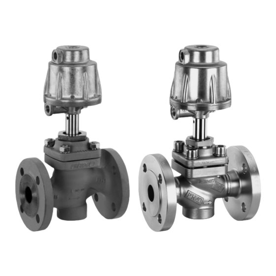
- Seite 1 Sitzventil Metall, DN 15 - 100 Globe Valve Metal, DN 15 - 100 ORIGINAL EINBAU- UND MONTAGEANLEITUNG INSTALLATION, OPERATING AND MAINTENANCE INSTRUCTIONS...
-
Seite 2: Inhaltsverzeichnis
Inhaltsverzeichnis Allgemeine Hinweise Voraussetzungen für die einwandfreie Allgemeine Hinweise Funktion des GEMÜ-Ventils: Allgemeine Sicherheitshinweise 2 Sachgerechter Transport und Lagerung Hinweise für Service- und Installation und Inbetriebnahme durch Bedienpersonal eingewiesenes Fachpersonal Warnhinweise Bedienung gemäß dieser Einbau- und Begriff sbestimmungen Montageanleitung Vorgesehener Einsatzbereich Ordnungsgemäße Instandhaltung Auslieferungszustand Korrekte Montage, Bedienung und Wartung... -
Seite 3: Warnhinweise
Gefährdung von Personen durch Warnhinweise sind dabei immer mit elektrische, mechanische und chemische einem Signalwort und teilweise auch Einwirkungen. mit einem gefahrenspezifischen Symbol Gefährdung von Anlagen in der gekennzeichnet. Umgebung. Folgende Signalwörter bzw. Versagen wichtiger Funktionen. Gefährdungsstufen werden eingesetzt: Gefährdung der Umwelt durch Austreten gefährlicher Stoff... -
Seite 4: Begriff Sbestimmungen
Max. zul. Viskosität 600 mm²/s Einsatzbereich Weitere Ausführungen für tiefere / höhere Temperaturen und höhere Viskositäten auf Anfrage. Das 2/2-Wege-Sitzventil GEMÜ 512 ist für den Einsatz in Rohrleitungen Leckrate konzipiert. Es steuert ein durchfl ießendes Auf-Zu-Ventil: Leckrate A nach P11/P12 EN 12266-1... - Seite 5 Betriebsdruck [bar] Steuerdruck [bar] Nennweite Gewicht [kg] Steuerfunktion 1* Steuerfunktion 1 Werte Antriebs- Antriebs- Antriebs- Antriebs- Antriebs- Antriebs- größe 1 größe 2 größe 1 größe 2 größe 1 größe 2 Kolben- Kolben- Kolben- Kolben- Kolben- Kolben- ø70 mm ø120 mm ø70 mm ø120 mm ø70 mm...
-
Seite 6: Bestelldaten
Antriebsgröße 2 / Steuerfunktion 2 Antriebsgröße 2 / Steuerfunktion 3 min. Steuerdruck in Abhängigkeit vom Betriebsdruck min. Steuerdruck in Abhängigkeit vom Betriebsdruck Betriebsdruck [bar] Betriebsdruck [bar] Bestelldaten Gehäuseform Code Steuerfunktion Code Durchgang Federkraft geschlossen (NC) Federkraft geöffnet (NO) Beidseitig angesteuert (DA) Anschlussart Code... -
Seite 7: Herstellerangaben
Herstellerangaben Funktionsbeschreibung Das fremdgesteuerte 2/2 Wege-Ventil Transport GEMÜ 512 ist ein Metall-Sitzventil mit Durchgangskörper und besitzt einen Ventil nur auf geeignetem Lademittel robusten wartungsarmen Aluminium transportieren, nicht stürzen, vorsichtig Kolbenantrieb. Die Ventilkörper sind gemäß handhaben. Datenblatt in verschiedenen Ausführungen Verpackungsmaterial entsprechend erhältlich. -
Seite 8: Montage Und Anschluss
Montage und Anschluss Montagearbeiten nur durch geschultes Fachpersonal. Geeignete Schutzausrüstung gemäß Vor Einbau: den Regelungen des Anlagenbetreibers Ventilkörperwerkstoff und Sitzdichtung berücksichtigen. entsprechend Betriebsmedium auslegen. Eignung vor Einbau prüfen! Installationsort: Siehe Kapitel 6 "Technische Daten". VORSICHT 11.1 Montage des Ventils Ventil äußerlich nicht stark WARNUNG beanspruchen. -
Seite 9: Steuerfunktionen
Montage: wieder anbringen bzw. in Funktion setzen. 1. Eignung des Ventils für jeweiligen 11.2 Steuerfunktionen Einsatzfall sicherstellen. Das Ventil muss für die Betriebsbedingungen Folgende Steuerfunktionen sind verfügbar: des Rohrleitungssystems (Medium, Mediumskonzentration, Temperatur Steuerfunktion 1 und Druck) sowie die jeweiligen Federkraft geschlossen (NC): Umgebungsbedingungen geeignet sein. -
Seite 10: Steuermedium Anschließen
Montage / Demontage von Anschluss 4 Ersatzteilen Siehe auch Kapitel 11.1 "Montage des Ventils" und Kapitel 20 "Schnittbilder und Anschluss 2 Ersatzteile". 12.1 Demontage Antrieb und Dichtring 30 1. Antrieb A in Off en-Position bringen. 2. Befestigungsteile lösen und entfernen. 3. -
Seite 11: Montage Antrieb Und Dichtring
11. Antrieb A in Geschlossen-Position Wichtig: bringen, auf Funktion und auf Dichtheit Austausch der Stahl-Sitzdichtung prüfen. nur durch GEMÜ. Komplettes Ventil mit ausgefüllter Wichtig: Rücksendeerklärung an GEMÜ Dichtring 4 bei jeder Demontage / senden. Montage des Antriebs austauschen. 12.3 Montage Antrieb und Dichtring 30 Inbetriebnahme 1. -
Seite 12: Demontage
Leitung des Steuermediums VORSICHT abschrauben (siehe Kapitel 11.3 Heiße Anlagenteile! "Steuermedium anschließen"). ® Verbrennungen! Nur an abgekühlter Anlage Entsorgung arbeiten. VORSICHT Alle Ventilteile entsprechend den Entsorgungs vorschriften / Wartungs- und Instandhaltungstätigkei- Umweltschutz bestimmungen ten nur durch geschultes Fachpersonal. entsorgen. Für Schäden welche durch unsach- Auf Restanhaftungen und gemäße Handhabung oder Fremdein- Ausgasung von eindiff... -
Seite 13: Fehlersuche / Störungsbehebung
Fehlersuche / Störungsbehebung Fehler Möglicher Grund Fehlerbehebung Steuermedium entweicht aus Entlüftung (Anschluss 4* Antrieb austauschen und Steuermedium auf Steuerkolben undicht bei NC / Anschluss 2* bei Verschmutzungen untersuchen Steuermedium entweicht Antrieb austauschen und Steuermedium auf Spindelabdichtung undicht aus Leckagebohrung* Verschmutzungen untersuchen Betriebsmedium entweicht Stopfbuchsenpackung defekt Antrieb austauschen... -
Seite 14: Schnittbilder Und Ersatzteile
Schnittbilder und Ersatzteile GEMÜ 512 mit Sitz- Anschluss 4 / dichtung aus PTFE Entlüftung bei Steuer- funktion 1 Anschluss 2 / Entlüftung bei Steuer- funktion 2 Leckage- bohrung Befestigungsteile Antriebsflansch Ventilkörper- flansch Pos. Benennung Bestellbezeichnung Ventilkörper K 500... Dichtring Sitzdichtung 512...SVS... -
Seite 15: Gemü 512 Mit Sitzdichtung Aus Stahl
GEMÜ 512 mit Sitz- Anschluss 4 / dichtung aus Stahl Entlüftung bei Steuer- funktion 1 Anschluss 2 / Entlüftung bei Steuer- funktion 2 Leckage- bohrung Befestigungsteile Antriebsflansch Ventilkörper- flansch Pos. Benennung Bestellbezeichnung Ventilkörper K 500... Dichtring 512...SVS... Dichtring Antrieb 9512 Überwurfmutter... -
Seite 16: Einbauerklärung
29.12.2009 Projektnummer: SV-Pneum-2009-12 Handelsbezeichnung: Typ 512 Es wird erklärt, dass die folgenden grundlegenden Anforderungen der Maschinenrichtlinie 2006/42/EG erfüllt sind: 1.1.3.; 1.1.5.; 1.1.7.; 1.2.1.; 1.3.; 1.3.2.; 1.3.3.; 1.3.4.; 1.3.7.; 1.3.9.; 1.5.3.; 1.5.5.; 1.5.6.; 1.5.7.; 1.5.8.; 1.5.9.; 1.6.5.; 2.1.1.; 3.2.1.; 3.2.2.; 3.3.2.; 3.4.4.; 3.6.3.1.; 4.1.2.1.; 4.1.2.3.; 4.1.2.4.; 4.1.2.5.; 4.1.2.6. a); 4.1.2.6. b);... -
Seite 17: Eg-Konformitätserklärung
GEMÜ Gebr. Müller Apparatebau GmbH & Co. KG Fritz-Müller-Straße 6-8 D-74653 Ingelfingen erklären, dass unten aufgeführte Armaturen die Sicherheitsanforderungen der Druckgeräte- richtlinie 97/23/EG erfüllen. Benennung der Armaturen - Typenbezeichnung Sitzventil GEMÜ 512 Benannte Stelle: TÜV Rheinland Berlin Brandenburg Nummer: 0035 Zertifikat-Nr.: 01 202 926/Q-02 0036 Konformitätsbewertungsverfahren:... - Seite 34 34 / 36...
- Seite 35 35 / 36...
- Seite 36 GEMÜ Gebr. Müller Apparatebau GmbH & Co. KG · Fritz-Müller-Str. 6-8 · D-74653 Ingelfi ngen-Criesbach Telefon +49(0)7940/123-0 · Telefax +49(0)7940/123-192 · info@gemue.de · www.gemu-group.com...