Gemü 566 Betriebsanleitung
Vorschau ausblenden
Andere Handbücher für 566:
- Betriebsanleitung (120 Seiten) ,
- Original einbau- und montageanleitung (64 Seiten) ,
- Beschreibung (19 Seiten)

Verwandte Anleitungen für Gemü 566


Inhaltszusammenfassung für Gemü 566
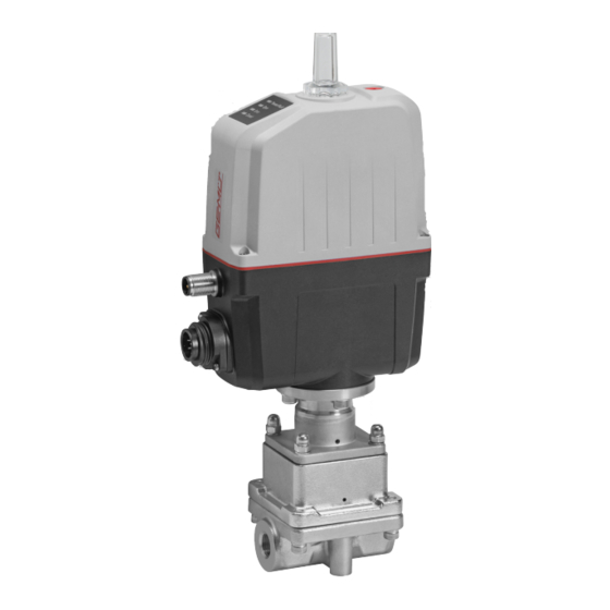
- Seite 1 GEMÜ 566 Elektromotorisch betätigtes Regelventil Motorized control valve Betriebsanleitung Operating instructions Weitere Informationen Webcode: GW-566...
- Seite 2 Alle Rechte wie Urheberrechte oder gewerbliche Schutzrechte werden ausdrücklich vorbehalten. All rights including copyrights or industrial property rights are expressly reserved. Dokument zum künftigen Nachschlagen aufbewahren. Keep the document for future reference. © GEMÜ Gebr. Müller Apparatebau GmbH & Co. KG 05.01.2021 GEMÜ 566 2 / 112 www.gemu-group.com...
-
Seite 3: Inhaltsverzeichnis
15 Fehlerbehebung ............52 16 Ausbau aus Rohrleitung ..........54 17 Entsorgung ............... 54 18 Rücksendung ............54 19 Konformitätserklärung nach 2014/68/EU (Druckgerä- terichtlinie) ............... 55 20 Konformitätserklärung nach 2014/30/EU (EMV-Richt- linie) ................. 56 www.gemu-group.com 3 / 112 GEMÜ 566... -
Seite 4: Allgemeines
Mögliche Folgen bei Nichtbeachtung. spezifisches Maßnahmen zur Vermeidung der Gefahr. Symbol Warnhinweise sind dabei immer mit einem Signalwort und teilweise auch mit einem gefahrenspezifischen Symbol ge- kennzeichnet. Folgende Signalwörter bzw. Gefährdungsstufen werden einge- setzt: GEMÜ 566 4 / 112 www.gemu-group.com... -
Seite 5: Sicherheitshinweise
13. Das Produkt ordnungsgemäß instand halten. 14. Wartungsarbeiten bzw. Reparaturen, die nicht in dem Do- kument beschrieben sind, nicht ohne vorherige Abstim- mung mit dem Hersteller durchführen. Bei Unklarheiten: 15. Bei nächstgelegener GEMÜ-Verkaufsniederlassung nach- fragen. www.gemu-group.com 5 / 112 GEMÜ 566... -
Seite 6: Led-Anzeigen
Das Produkt ist bestimmungsgemäß nicht für den Einsatz in elle, pneumatische und elektromotorische Antriebsarten zur explosionsgefährdeten Bereichen geeignet. Verfügung. Das Ventil GEMÜ 566 wurde speziell für die Rege- lung von Kleinmengen entwickelt und erlaubt einen Durchfluss ● Das Produkt gemäß den technischen Daten einsetzen. -
Seite 7: Bestelldaten
ASTM A 351 CF3M, Feinguss 6 Dichtwerkstoff 7 Spannung/Frequenz 24 V DC 8 Regelmodul Stellungsregler 9 Regelkurve modifiziert gleichprozentig 10 Kv-Wert 63 l/h 11 Antriebsausführung Antriebsgröße 0 12 CONEXO integrierter RFID-Chip zur elektronischen Identifizierung und Rückver- folgbarkeit www.gemu-group.com 7 / 112 GEMÜ 566... -
Seite 8: Technische Daten
Kv-Werte: Hub [%] Gleichprozentig (Anschluss-Code 1) / Linear (Anschluss-Code 1) Regelkurve Sitz Ø [mm] Kv-Wert DN 8 DN 10 DN 15 G, L G, L G, L 1000 G, L 1600 G, L 2500 GEMÜ 566 8 / 112 www.gemu-group.com... -
Seite 9: Mechanische Daten
Auf/Zu Betrieb - Mindestens 500.000 Schaltzyklen bei Raumtemperatur und zulässiger Einschalt- dauer. Mechanische Umweltbe- Klasse 4M8 nach EN 60721-3-4:1998 dingungen: Vibration: 5g nach IEC 60068-2-6 Test Fc Schocken: 25g nach IEC 60068-2-27 Test Ea www.gemu-group.com 9 / 112 GEMÜ 566... -
Seite 10: Elektrische Daten
Eingänge: Funktion über IO-Link wählbar (siehe Tabelle Funktionsübersicht Ein- und Ausgangssignale) Eingangsspannung: 24 V DC Pegel logisch ”1”: > 15,3 V DC Pegel logisch ”0”: < 5,8 V DC Eingangsstrom: typ. < 0,5 mA GEMÜ 566 10 / 112 www.gemu-group.com... -
Seite 11: Digitale Ausgangssignale
20 ms (eSyStep Stellungsregler, Code S0, S5, S6) Vendor-ID: Device-ID: 1906801 (eSyStep Stellungsregler, Code S0, S5, S6), Product-ID: eSyStep Positioner (Code S0, S5, S6) ISDU Unterstützung: SIO Betrieb: IO-Link Spezifikation: V1.1 IODD-Dateien können über https://ioddfinder.io-link.com/ oder www.gemu-group.com heruntergeladen werden. www.gemu-group.com 11 / 112 GEMÜ 566... -
Seite 12: Abmessungen
8.1 Einbau- und Antriebsmaße 8.1.1 Ventil mit Gewindemuffe, Code 1 Antriebsaus- führung 32,0 59,4 81,0 133,5 197,7 282,2 117,7 32,0 59,4 81,0 133,5 197,7 282,2 117,7 32,0 59,4 81,0 133,5 197,7 282,2 117,7 Maße in mm GEMÜ 566 12 / 112 www.gemu-group.com... -
Seite 13: Körpermaße
15,0 9,40 25,0 117,0 33,0 15,0 15,75 25,0 Maße in mm 1) Anschlussart Code 88: Clamp ASME BPE, Baulänge FTF EN 558 Reihe 7 2) Werkstoff Ventilkörper Code C1: ASTM A 351 CF3M, Feinguss www.gemu-group.com 13 / 112 GEMÜ 566... -
Seite 14: Ventilkörperbefestigung
8 Abmessungen 8.3 Ventilkörperbefestigung 8,10,15,20 Maße in mm GEMÜ 566 14 / 112 www.gemu-group.com... -
Seite 15: Herstellerangaben
Das Produkt nicht als Trittstufe oder Steighilfe benutzen. ● HINWEIS Eignung des Produkts! ▶ Das Produkt muss für die Betriebsbedingungen des Rohr- leitungssystems (Medium, Mediumskonzentration, Tem- peratur und Druck) sowie die jeweiligen Umgebungsbe- dingungen geeignet sein. www.gemu-group.com 15 / 112 GEMÜ 566... -
Seite 16: Einbaulage
10.2 Einbaulage 5. Alle Sicherheits- und Schutzeinrichtungen wieder anbrin- gen bzw. in Funktion setzen. GEMÜ empfiehlt eine senkrecht stehende oder hängende Ein- baulage des Antriebs zur Optimierung der Standzeit. 10.3 Einbau mit Gewindemuffe Abb. 1: Gewindemuffe GEMÜ 566 16 / 112 www.gemu-group.com... -
Seite 17: Elektrischer Anschluss
7-poliger Stecker Fa. Binder, Typ 693 Signalname Uv, 24 V DC Versorgungsspannung Digitaleingang 1 Digitaleingang 2 Digitalein- / ausgang Digitalausgang, IO-Link n.c. Anschluss X2 5-poliger M12-Einbaustecker, A-kodiert Signalname I+/U+, Sollwerteingang I-/U-, Sollwerteingang I+/U+, Istwertausgang www.gemu-group.com 17 / 112 GEMÜ 566... -
Seite 18: Funktionsübersicht Ein- Und Ausgangssignale
Auf / Zu / Error / Error+Warnung Analogeingang 4 – 20 mA / 0 – 20 mA / 0 – 4 – 20 mA 4 – 20 mA 10 V Analogausgang 4 – 20 mA / 0 – 20 mA / 0 – 4 – 20 mA 4 – 20 mA 10 V GEMÜ 566 18 / 112 www.gemu-group.com... -
Seite 19: Spezifische Daten Io-Link (Pin 6)
2. Pin 4 (CQ) des Masters mit Pin 6 des Produkts verbinden. Im IO-Link Betrieb kann Pin 6 nicht als Ausgangssignal von der SPS-Steuerung ausgewertet werden. Position Benennung eSyStep SPS mit Versorgungsspannung USB IO-Link Master Galvanisch getrennte USB-Schnittstelle Netzstecker Laptop www.gemu-group.com 19 / 112 GEMÜ 566... - Seite 20 2. Pin 4 (CQ) des Masters mit Pin 6 des Produkts verbinden. Im IO-Link Betrieb kann Pin 6 nicht als Ausgangssignal von der SPS-Steuerung ausgewertet werden. Position Benennung eSyStep SPS mit Versorgungsspannung USB IO-Link Master USB-Schnittstelle Netzstecker Laptop GEMÜ 566 20 / 112 www.gemu-group.com...
-
Seite 21: Betrieb An Io-Link-Master Direkt
Spannungsversorgungen verbunden ist. In dem Fall erfolgt der Anschluss des Masters wie bei gleicher Spannungs- versorgung ● Pin 4 (CQ) IO-Link Master mit Pin 6 des Produkts verbinden. Pin 3 (L-) IO-Link Master nicht anschließen. (L-) Position Benennung eSyStep B1 und B2 Versorgungsspannungen USB IO-Link Master www.gemu-group.com 21 / 112 GEMÜ 566... -
Seite 22: Prozessdaten
0 → Process valve not in Closed position 1 → Process valve in Closed position Operating mode 0 → Normal operation 1 → Initialization mode Valve position analog 8 … 23 Position of the valve in the range 0 … 1000 GEMÜ 566 22 / 112 www.gemu-group.com... -
Seite 23: Parameterübersicht
„eSyStep Positio- ner“ 0x13 Product ID Produkt ID auslesen „eSyStep Positio- ner“ 0x15 Serial number Seriennummer aus- „XXXXXXXX/YYYY“ lesen 0x16 Hardware revision Hardware Version „Rev. XX/XX“ auslesen 0x17 Firmware revision Softwareversion „V X.X.X.X.“ auslesen www.gemu-group.com 23 / 112 GEMÜ 566... -
Seite 24: Werks-Einstellmöglichkei- Einstellungen
Logischen Digitalen 0 → Active high outputs Eingang 1 konfigu- 1 → Active low rieren R / W Input 2 Logischen Digitalen 0 → Active high Eingang 2 konfigu- 1 → Active low rieren GEMÜ 566 24 / 112 www.gemu-group.com... - Seite 25 0x60 Analog values Poti Analogwert Poten- 0 … 4095 tiometer Supply voltage Analogwert Versor- 0 … 4095 gungsspannung Temperature Analogwert Tempe- 0 … 4095 ratursensor Set value (W) Analogwert Soll- 0 … 4095 wertsignal www.gemu-group.com 25 / 112 GEMÜ 566...
- Seite 26 U max Maximalen Span- 100 … 110 nungseingang fest- (10,0 … 11,0 V) legen 0xBA R / W Analog output Direction Wertrichtung Soll- 0 → Rise (steigend) wertausgang ein- 1 → Fall (fallend) stellen GEMÜ 566 26 / 112 www.gemu-group.com...
- Seite 27 2 → 0 … 10 V R / W Minimalen Signal- 0 … Max ausgang festlegen (0,0 % … Max) R / W Maximalen Signal- 1000 Min … 1000 ausgang festlegen (Min … 100 %) www.gemu-group.com 27 / 112 GEMÜ 566...
-
Seite 28: Parameter
0x03 R / W 1 Byte Data storage index Data Storage Cmd UIntegerT8 1 Byte State Property UIntegerT8 4 Byte Data Storage Size UIntegerT32 4 Byte Parameter Checks- UIntegerT32 41 Byte Index List OctetStringT GEMÜ 566 28 / 112 www.gemu-group.com... -
Seite 29: Device Access Locks
Indexname Parameter Type Values Index Rights 0x0D 8 Byte Profile ArrayT 0x8000 Characteristics 0x8002 0x8003 0x8100 Beschreibung Parameterwerte Indexname Parameter Werte Beschreibung Profile Characteristics 0x8000 Geräte-Identifikation Objekte 0x8002 Prozessdatenabbildung 0x8003 Diagnose 0x8100 Externe Identifikation www.gemu-group.com 29 / 112 GEMÜ 566... -
Seite 30: Product Name
12.4.8 Product name Mit dem Parameter Product name kann der Gerätename im ASCII Format ausgelesen werden. Index Sub- Off- Access Length Indexname Parameter Type Values Index Rights 0x12 18 Byte Product name StringT "eSyStep Positioner" GEMÜ 566 30 / 112 www.gemu-group.com... -
Seite 31: Hardware Revision
Mit dem Parameter Application specific tag kann ein 32 Zeichen langer Text im Gerät gespeichert werden. Zum Beispiel Einbauort, Funktion, Einbau-Datum..Index Sub- Off- Access Length Indexname Parameter Type Values Index Rights 0x18 R / W 32 Byte Application StringT „**************** " specific tag www.gemu-group.com 31 / 112 GEMÜ 566... -
Seite 32: Device Status
Index Sub- Off- Access Length Indexname Parameter Type Values Index Rights 0x25 39 Byte Detailed Device Sta- ArrayT Siehe Kapitel 12.5 Events Beschreibung Parameterwerte Indexname Parameter Werte Beschreibung Detailed Device Status Siehe Kapitel 12.5 Events GEMÜ 566 32 / 112 www.gemu-group.com... - Seite 33 Mit dem Parameter Function digital inputs können Funktionen der digitalen Eingänge konfiguriert werden. Index Sub- Off- Access Length Indexname Parameter Type Default Values Rights 0x4B R / W 3 Bit Function digital in- Input 1 uint:8 puts R / W 3 Bit Input 2 uint:8 www.gemu-group.com 33 / 112 GEMÜ 566...
-
Seite 34: Beschreibung
Bei aktivem Signal arbeitet das Gerät normal. Bei Weg- fall des Signals fährt das Gerät in Sicherheitsstellung. Die Si- cherheitsstellung wird mittels des Parameters Error Action (Index 0x4F (siehe 'Error Action')) definiert. (Init) Eingang kann als Initialisierungs-Eingang verwendet werden. GEMÜ 566 34 / 112 www.gemu-group.com... - Seite 35 (Output Error & Warning) Fehler und Warnungen ausgeben. (Input Init) Ein- / Ausgang als Initialisierungseingang konfigu- rieren. Type in- / output (Push-Pull) Ausgang als Push-Pull konfigurieren. (NPN) Ausgang als NPN konfigurieren. (PNP) Ausgang als PNP konfigurieren. www.gemu-group.com 35 / 112 GEMÜ 566...
- Seite 36 (Active high) Eingang 2 nicht invertiert. (Active low) Eingang 2 invertiert. Input / output 1 (Active high) Ein- / Ausgang nicht invertiert. (Active low) Ein- / Ausgang invertiert. Output 2 (Active high) Ausgang nicht invertiert. (Active low) Ausgang invertiert. GEMÜ 566 36 / 112 www.gemu-group.com...
- Seite 37 (Hold) Antrieb bleibt bei einem Fehler in der aktuellen Stel- lung stehen. (Open) Antrieb fährt bei einem Fehler in Stellung AUF. (Close) Antrieb fährt bei einem Fehler in Stellung ZU. Error time 1 … 1000 Zeitverzögerung zwischen Fehlererkennung und Fehlermel- dung festlegen. www.gemu-group.com 37 / 112 GEMÜ 566...
-
Seite 38: Basic Settings
Betriebsmodus für Stellungsregler aktiviert. Betriebsmodus für AUF/ZU-Steuerung aktiviert. IO-Link process data (Disabled) Verwendung von IO-Link Prozessdaten (siehe Ka- pitel 12.2, Seite 22) ist deaktiviert. (Enabled) Verwendung von IO-Link Prozessdaten (siehe Kapi- tel 12.2, Seite 22) ist aktiviert. GEMÜ 566 38 / 112 www.gemu-group.com... - Seite 39 0 … 4092 Beschreibung Parameterwerte Indexname Parameter Werte Beschreibung Initialized positions Open 0 … 4092 Analogwert Ventilstellung AUF Close 0 … 4092 Analogwert Ventilstellung ZU Stroke 0 … 4092 Analogwert Hub (Differenz zwischen AUF und ZU). www.gemu-group.com 39 / 112 GEMÜ 566...
- Seite 40 Aktuellen Analogwert des Potentiometers auslesen. Supply voltage 0 … 4095 Aktuellen Analogwert der Versorgungsspannung auslesen. Temperature 0 … 4095 Aktuellen Analogwert des Temperatursensors auslesen. Set value (W) 0 … 4095 Aktuellen Analogwert des Sollwerts auslesen. GEMÜ 566 40 / 112 www.gemu-group.com...
-
Seite 41: Operating Times
Kraft des Ventils einstellen. Werkseitig je nach Ventiltyp vor- eingestellt. Force initialization 1 … 6 Kraft während der Initialisierung einstellen. Werksseitig je nach Ventiltyp voreingestellt. Krafteinstellungen Antriebsgröße Einstellparameter Kraft AG0 und AG1 Kleinste Kraft Maximale Kraft www.gemu-group.com 41 / 112 GEMÜ 566... -
Seite 42: Control Parameters
Indexname Parameter Werte Beschreibung Open / close tight Open tight 800 … 1000 Dichtschließfunktion Ventilposition AUF einstellen. (80,0 … 100,0 %) Close tight 0 … 200 Dichtschließfunktion Ventilposition ZU einstellen. (0 … 20,0 %) GEMÜ 566 42 / 112 www.gemu-group.com... -
Seite 43: Split Range
Min Pos … 1000 Hubbegrenzung des Regelbereichs in Ventilposition AUF ein- (Min Pos … stellen. 100,0 %) Min pos 0 … Max Pos Hubbegrenzung des Regelbereichs in Ventilposition ZU ein- (0,0 % … Max stellen. Pos) www.gemu-group.com 43 / 112 GEMÜ 566... - Seite 44 Wert überschritten, kommt die Meldung „Sollwert zu groß“. U max 100 … 110 Maximalen Wert des Spannungseingangs festlegen. Wird der (10,0 … 11,0 V) eingestellte Wert überschritten, kommt die Meldung „Sollwert zu hoch. GEMÜ 566 44 / 112 www.gemu-group.com...
-
Seite 45: Analog Output
Das Event tritt auf, wenn der Ventil ist blockiert (zum Bei- Ventil prüfen 0x8CE0 Motor blockiert ist. spiel Festkörper im Ventil ein- Ist das Ventil in Ordnung, Initia- geklemmt). lisierung durchführen Ventil korrodiert (fest geros- tet). www.gemu-group.com 45 / 112 GEMÜ 566... - Seite 46 Ventilstellung gelesen wird, die tilposition. in Richtung „Open“ nie erreicht Fehler beim Tausch einer werden kann. Membrane (Hub des Ventils im falschen Bereich). Antrieb wurde falsch auf Ventil aufgebaut (Hub des Ventils im falschen Bereich). GEMÜ 566 46 / 112 www.gemu-group.com...
-
Seite 47: Bedienung
ð LEDs OPEN und CLOSED blinken alternierend. 2. Ventil fährt automatisch in Stellung AUF. 3. Ventil fährt automatisch in Stellung ZU. 4. Initialisierungsmodus wird automatisch beendet. 5. Endlagen sind eingestellt. www.gemu-group.com 47 / 112 GEMÜ 566... -
Seite 48: Inspektion Und Wartung
Bestellbezeich- Nur an abgekühlter Anlage arbeiten. nung ● Antrieb 9566… Trennmembrane 566 000 PAM 4/33 HINWEIS 14.2 Antrieb demontieren Außergewöhnliche Wartungsarbeiten! ▶ Beschädigungen des GEMÜ Produkts. 1. Antrieb A in Offen-Position bringen. Wartungsarbeiten bzw. Reparaturen, die nicht in dieser ●... -
Seite 49: Regelkegel Austauschen
8. Ventilspindel 21 und Regelkegel 3 mit montierter Trenn- membrane 2 nach unten herausziehen. 7. Sicherungsring 28 entfernen. ð Druckfeder 23 steht unter Spannung. 8. Ventilspindel 21 und Regelkegel 3 mit montierter Trenn- membrane 2 nach unten herausziehen. www.gemu-group.com 49 / 112 GEMÜ 566... -
Seite 50: Montage Ohne Montagewerkzeug
Teile dabei nicht beschädigen. Danach Teile auf Be- fest montieren. schädigung prüfen. Wenn Teile beschädigt sind, diese 7. Innensechskantschrauben 6 über Kreuz festziehen. dann auswechseln. 14.5.2 Demontage mit Montagewerkzeug 1. Regelkegel demontieren (siehe Kapitel Demontage Regel- kegel). GEMÜ 566 50 / 112 www.gemu-group.com... -
Seite 51: Reinigung Des Produkts
Teile dabei nicht beschädigen. Danach Teile auf Be- 14.6 Reinigung des Produkts schädigung prüfen. Wenn Teile beschädigt sind, diese dann auswechseln. • Das Produkt mit feuchtem Tuch reinigen. • Das Produkt nicht mit Hochdruckreiniger reinigen. www.gemu-group.com 51 / 112 GEMÜ 566... -
Seite 52: Fehlerbehebung
Open und Closed blinken alternierend Temperatur Fehler Betrieb Notstrom, Stellung AUF Betrieb Notstrom, Stellung ZU Betrieb Notstrom, Stellung unbekannt Sollwert zu klein Sollwert zu groß Wartung nötig, Stellung AUF Wartung nötig, Stellung ZU Wartung nötig, Stellung unbekannt GEMÜ 566 52 / 112 www.gemu-group.com... - Seite 53 Körper des GEMÜ Produkts defekt oder Körper des GEMÜ Produkts auf Beschädi- korrodiert gungen prüfen, ggf. Körper tauschen Unsachgemäße Montage Montage Ventilkörper in Rohrleitung prü- Verbindung Ventilkörper – Rohrleitung Unsachgemäße Montage Montage Ventilkörper in Rohrleitung prü- undicht www.gemu-group.com 53 / 112 GEMÜ 566...
-
Seite 54: Ausbau Aus Rohrleitung
1. Das Produkt reinigen. Medien achten. 2. Rücksendeerklärung bei GEMÜ anfordern. 2. Alle Teile entsprechend der Entsorgungsvorschriften / Um- 3. Rücksendeerklärung vollständig ausfüllen. weltschutzbedingungen entsorgen. 4. Das Produkt mit ausgefüllter Rücksendeerklärung an GEMÜ schicken. GEMÜ 566 54 / 112 www.gemu-group.com... -
Seite 55: Konformitätserklärung Nach 2014/68/Eu (Druckgeräterichtlinie)
Wir, die Firma GEMÜ Gebr. Müller Apparatebau GmbH & Co. KG Fritz-Müller-Straße 6-8 D-74653 Ingelfingen-Criesbach erklären, dass das unten aufgeführte Produkt die Sicherheitsanforderungen der Druckgeräterichtlinie 2014/68/EU erfüllt. Benennung des Druckgerätes: GEMÜ 566 Benannte Stelle: TÜV Rheinland Industrie Service GmbH Nummer: 0035 Zertifikat-Nr.: 01 202 926/Q-02 0036 Konformitätsbewertungsverfahren:... -
Seite 56: Konformitätserklärung Nach 2014/30/Eu (Emv-Richtlinie)
GEMÜ Gebr. Müller Apparatebau GmbH & Co. KG Fritz-Müller-Straße 6-8 D-74653 Ingelfingen-Criesbach erklären, dass das unten aufgeführte Produkt die Sicherheitsanforderungen der EMV-Richtlinie 2014/30/EU erfüllt. Benennung des Produktes: GEMÜ 566 Angewandte Normen: Allgemeine Anforderungen IEC 61326-1:2012: • DIN EN 61000-6-4:2007/A1:2011 Störfestigkeit: •... - Seite 111 GEMÜ 566 111 / 112 www.gemu-group.com...