Gemü 554 Benutzerhandbuch Und Montageanleitung
Vorschau ausblenden
Andere Handbücher für 554:
- Original einbau- und montageanleitung (44 Seiten) ,
- Montageanleitung (36 Seiten) ,
- Betriebsanleitung (30 Seiten)

Verwandte Anleitungen für Gemü 554


Inhaltszusammenfassung für Gemü 554
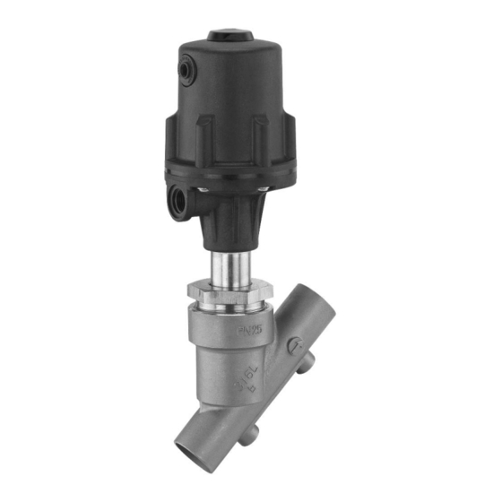
- Seite 1 Schrägsitzventil Metall, DN 6 - 80 Angle Seat Globe Valve Metal, DN 6 - 80 ORIGINAL EINBAU- UND MONTAGEANLEITUNG INSTALLATION, OPERATING AND MAINTENANCE INSTRUCTIONS...
-
Seite 2: Inhaltsverzeichnis
Inhaltsverzeichnis Allgemeine Hinweise Voraussetzungen für die einwandfreie Allgemeine Hinweise Funktion des GEMÜ-Ventils: Allgemeine Sicherheitshinweise 2 Sachgerechter Transport und Lagerung Hinweise für Service- und Installation und Inbetriebnahme durch Bedienpersonal eingewiesenes Fachpersonal Warnhinweise Bedienung gemäß dieser Einbau- und Verwendete Symbole Montageanleitung Begriff sbestimmungen Ordnungsgemäße Instandhaltung Vorgesehener Einsatzbereich Auslieferungszustand... -
Seite 3: Hinweise Für Service- Und
Hinweise für Service- und Warnhinweise Bedienpersonal Warnhinweise sind, soweit möglich, nach folgendem Schema gegliedert: Die Einbau- und Montageanleitung enthält grundlegende Sicherheitshinweise, die bei SIGNALWORT Inbetriebnahme, Betrieb und Wartung zu beachten sind. Nichtbeachtung kann zur Art und Quelle der Gefahr Folge haben: ®... -
Seite 4: Verwendete Symbole
Vorgesehener Verwendete Symbole Einsatzbereich Gefahr durch heiße Oberfl ächen! Das 2/2-Wege-Schrägsitzventil GEMÜ 554 ist für den Einsatz in Gefahr durch ätzende Stoff e! Rohrleitungen konzipiert. Es steuert ein durchfl ießendes Medium indem es durch ein Steuermedium geschlossen oder Hand: Beschreibt allgemeine geöff... -
Seite 5: Technische Daten
Technische Daten Ausführungen 0K, 1K, 2K, 3L und 4L gelten nur für Anschlussart Code 80 in Kombination mit Ventilkörperwerkstoff C2 (nur DN 15, 20, 25, 40, 50 und 65 / Antrieb B nicht verfügbar). Betriebsmedium Antriebsdaten Aggressive, neutrale, gasförmige und flüssige Medien, die Kolben- Antriebsgröße Füllvolumen... - Seite 6 Druck- / Temperatur-Zuordnung für Schrägsitz-Ventilkörper Zulässige Betriebsdrücke in bar bei Temperatur in °C* Werkstoff- Anschluss-Code Code 1, 3C, 3D, 9 (bis DN 50) 16,0 16,0 16,0 13,5 1, 9 (ab DN 65) 10,0 10,0 10,0 1, 9, 17, 37, 59, 60, 3C, 3D 25,0 23,8 21,4...
- Seite 7 Antriebsgröße 4L Federkraft geschlossen (NC) min. Steuerdruck in Abhängigkeit vom Betriebsdruck (Durchflussrichtung: mit dem Teller) DN 65 DN 50 DN 40 DN 25 DN 20 DN 15 Betriebsdruck [bar] Betriebsdruck [bar] Betriebsdruck- / Steuerdruckkennlinien - Antriebsgrößen 0, 1, 2, 3, 4 Antriebsgröße 0 Antriebsgröße 1 Antriebsgröße 2...
-
Seite 8: Bestelldaten
Medien um "Wasserschläge" zu vermeiden Clamp-Stutzen ** nur Steuerfunktion NC Clamp ASME BPE für Rohr ASME BPE, Baulänge ASME BPE GEMÜ 554 GEMÜ 554 Antriebe Antriebe Clamp DIN 32676 Reihe B für Rohr EN ISO 1127, B, 0, 0K, 1, 1K, 3, 3L, 4, 4L Baulänge EN 558, Reihe 1... -
Seite 9: Herstellerangaben
Herstellerangaben Funktionsbeschreibung Das fremdgesteuerte 2/2 Wege-Ventil Transport GEMÜ 554 ist ein Metall-Schrägsitzventil mit Durchgangskörper und besitzt einen Ventil nur auf geeignetem Lademittel pneumatischen Kunststoff-Kolbenantrieb. transportieren, nicht stürzen, vorsichtig Ventilkörper und Sitzdichtung sind gemäß handhaben. Datenblatt in verschiedenen Ausführungen Verpackungsmaterial entsprechend erhältlich.Vielfältiges Zubehör ist lieferbar,... -
Seite 10: Montage Und Anschluss
Montage und Anschluss Installationsort: VORSICHT Vor Einbau: Ventil äußerlich nicht stark beanspruchen. Eignung Ventilkörper- und Dichtwerkstoff Installationsort so wählen, dass Ventil entsprechend Betriebsmedium prüfen. nicht als Steighilfe genutzt werden Siehe Kapitel 6 "Technische Daten". kann. Rohrleitung so legen, dass Schub- und 11.1 Montage des Ventils Biegungskräfte, sowie Vibrationen und... -
Seite 11: Steuerfunktionen
Montage: Montage bei Clampanschluss: 1. Eignung des Ventils für jeweiligen Bei Montage der Clampanschlüsse Einsatzfall sicherstellen. Das Ventil entsprechende Dichtung zwischen muss für die Betriebsbedingungen Ventilkörper und Rohranschluss einlegen des Rohrleitungssystems (Medium, und mit Klammer verbinden. Die Dichtung Mediumskonzentration, Temperatur sowie die Klammer der Clampanschlüsse und Druck) sowie die jeweiligen sind nicht im Lieferumfang enthalten. -
Seite 12: Beidseitig Angesteuert (In Ruhestellung Geöffnet)
Nur für Regelventile: Steuerfunktion 8 Steuerfunktion Anschlüsse Beidseitig angesteuert (in Ruhestellung Federkraft 2: Steuermedium (Öffnen) geöffnet): geschlossen (NC) Ruhezustand des Ventils: durch Federkraft Federkraft geöffnet 4: Steuermedium (Schließen) geöffnet. Öffnen und Schließen des Ventils (NO) durch Ansteuern der entsprechenden Beidseitig 2: Steuermedium (Öffnen) angesteuert (DA) 4: Steuermedium (Schließen) -
Seite 13: Montage Antrieb
1. Antrieb A demontieren wie in Kapitel Typenschild Antrieb Ventilkörperkennzeichnung 12.1, Punkte 1-4 beschrieben. RGxxx R015 2. Dichtring 4 entnehmen. RHxxx R020 3. Mutter d an der Spindel b lösen RJxxx R025 (Spindel b mit geeignetem Werkzeug, das die Spindeloberfl äche nicht RKxxx R032 beschädigt, festhalten). -
Seite 14: Inbetriebnahme
VORSICHT Antriebe 0K, 1K, 2K, 3L und 4L Nennweite Drehmomente [Nm] Heiße Anlagenteile! DN 15 ® Verbrennungen! DN 20 Nur an abgekühlter Anlage DN 25 arbeiten. DN 40 DN 50 VORSICHT DN 65 Wartungs- und Instandhaltungstätigkeiten nur durch Inbetriebnahme geschultes Fachpersonal. Für Schäden welche durch WARNUNG unsachgemäße Handhabung oder... -
Seite 15: Demontage
Rücksendung GEMÜ 554 Antriebsgröße B Ventil reinigen. Rücksendeerklärung bei GEMÜ anfordern. Rücksendung nur mit vollständig ausgefüllter Rücksendeerklärung. Ansonsten erfolgt keine Gutschrift bzw. keine Erledigung der Reparatur Ansatz für sondern eine kostenpflichtige Entsorgung. Hakenschlüssel mit Zapfen Hinweis zur Rücksendung: Zapfengröße 3 mm... -
Seite 16: Fehlersuche / Störungsbehebung
Fehlersuche / Störungsbehebung Fehler Möglicher Grund Fehlerbehebung Steuermedium entweicht aus Entlüftungsbohrung* Antrieb austauschen und Steuermedium auf bei Steuerfunktion NC / Steuerkolben undicht Verschmutzungen untersuchen Anschluss 2* bei Steuerfunktion NO Steuermedium entweicht Antrieb austauschen und Steuermedium auf Spindelabdichtung undicht aus Leckagebohrung* Verschmutzungen untersuchen Betriebsmedium entweicht Stopfbuchspackung defekt... -
Seite 17: Schnittbild Und Ersatzteile
Schnittbild und Ersatzteile Anschluss 4 / Entlüftungsbohrung bei Steuerfunktion Anschluss 2 / Entlüftungsbohrung bei Steuerfunktion Leckagebohrung Pos. Benennung Bestellbezeichnung Ventilkörper K514... Dichtring 554...SVS... Sitzdichtung (nicht bei Antriebsgröße B) Antrieb 9554... Überwurfmutter Spindel Ventilteller Mutter Scheibe 17 / 40... -
Seite 18: Einbauerklärung
29.12.2009 Projektnummer: SV-Pneum-2009-12 Handelsbezeichnung: Typ 554 Es wird erklärt, dass die folgenden grundlegenden Anforderungen der Maschinenrichtlinie 2006/42/EG erfüllt sind: 1.1.3.; 1.1.5.; 1.1.7.; 1.2.1.; 1.3.; 1.3.2.; 1.3.3.; 1.3.4.; 1.3.7.; 1.3.9.; 1.5.3.; 1.5.5.; 1.5.6.; 1.5.7.; 1.5.8.; 1.5.9.; 1.6.5.; 2.1.1.; 3.2.1.; 3.2.2.; 3.3.2.; 3.4.4.; 3.6.3.1.; 4.1.2.1.; 4.1.2.3.; 4.1.2.4.; 4.1.2.5.; 4.1.2.6. a); 4.1.2.6. b);... -
Seite 19: Eg-Konformitätserklärung
GEMÜ Gebr. Müller Apparatebau GmbH & Co. KG Fritz-Müller-Straße 6-8 D-74653 Ingelfingen erklären, dass unten aufgeführte Armaturen die Sicherheitsanforderungen der Druckgeräte- richtlinie 97/23/EG erfüllen. Benennung der Armaturen - Typenbezeichnung Sitzventil GEMÜ 554 Benannte Stelle: TÜV Rheinland Berlin Brandenburg Nummer: 0035 Zertifikat-Nr.: 01 202 926/Q-02 0036 Konformitätsbewertungsverfahren:... - Seite 38 38 / 40...
- Seite 39 39 / 40...
- Seite 40 GEMÜ Gebr. Müller Apparatebau GmbH & Co. KG · Fritz-Müller-Str. 6-8 · D-74653 Ingelfi ngen-Criesbach Telefon +49(0)7940/123-0 · Telefax +49(0)7940/123-192 · info@gemue.de · www.gemu-group.com...