Gemü 613 Montageanleitung
Inhaltsverzeichnis
Verfügbare Sprachen
Verfügbare Sprachen
Quicklinks
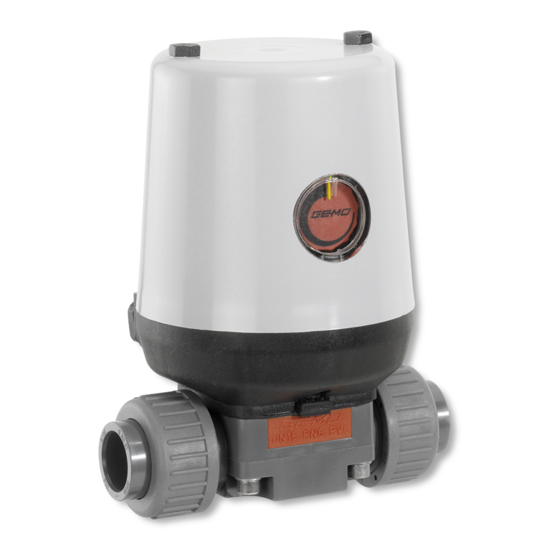
Motorgesteuerte Membranventile
Motorized Diaphragm Valves
ORIGINAL EINBAU- UND MONTAGEANLEITUNG
DE
INSTALLATION, OPERATING AND
GB
MAINTENANCE INSTRUCTIONS
GEMÜ 613 Kunststoff ausführung
GEMÜ 613 Plastic version
Metall / Kunststoff , DN 4 - 20
Metal / Plastic, DN 4 - 20
613, 618
GEMÜ 618 Metallausführung
GEMÜ 618 Metal version
613, 618
Kapitel
Inhaltsverzeichnis
Fehlerbehebung

Verwandte Anleitungen für Gemü 613


Inhaltszusammenfassung für Gemü 613
- Seite 1 Metall / Kunststoff , DN 4 - 20 Motorized Diaphragm Valves Metal / Plastic, DN 4 - 20 ORIGINAL EINBAU- UND MONTAGEANLEITUNG INSTALLATION, OPERATING AND MAINTENANCE INSTRUCTIONS GEMÜ 613 Kunststoff ausführung GEMÜ 618 Metallausführung GEMÜ 613 Plastic version GEMÜ 618 Metal version 613, 618...
-
Seite 2: Inhaltsverzeichnis
Inspektion und Wartung Verwendete Symbole Demontage Begriff sbestimmungen Entsorgung Vorgesehener Einsatzbereich Rücksendung Auslieferungszustand Hinweise Technische Daten Fehlersuche / Technische Daten GEMÜ 613 Störungsbehebung Technische Daten GEMÜ 618 Schnittbilder und Ersatzteile Bestelldaten Einbauerklärung Bestelldaten GEMÜ 613 EG-Konformitätserklärung Bestelldaten GEMÜ 618 Herstellererklärung Herstellerangaben... -
Seite 3: Allgemeine Sicherheitshinweise
Nur entsprechend der Leistungsdaten Möglicherweise gefährliche Situation! betreiben. Bei Nichtbeachtung drohen ® Wartungsarbeiten bzw. Reparaturen, Sachschäden. die nicht in der Einbau- und Montageanleitung beschrieben sind dürfen nicht ohne vorherige Abstimmung mit dem Hersteller durchgeführt werden. 613, 618 3 / 64... -
Seite 4: Verwendete Symbole
Vorgesehener Verwendete Symbole Einsatzbereich Gefahr durch heiße Oberflächen! Das GEMÜ-Membranventil 613 / 618 ist für den Einsatz in Rohrleitungen Gefahr durch ätzende Stoffe! konzipiert. Es steuert ein durchfl ießendes Medium indem es durch einen motorischen Stellantrieb geschlossen Quetschgefahr! oder geöff net werden kann. -
Seite 5: Technische Daten
Technische Daten Technische Daten GEMÜ 613 Betriebsmedium Schutzart Aggressive, neutrale, gasförmige und flüssige Medien, die IP 65 nach DIN 40050 die physikalischen und chemischen Eigenschaften des jeweiligen Gehäuse- und Membranwerkstoffes nicht negativ beeinflussen. Stellzeit Siehe Antriebsausführung (siehe Kapitel 7.1) Temperatur Betriebsmedium ca. - Seite 6 Die Kv-Werte für andere Produktkonfigurationen (z. B. andere Membran- oder Körperwerkstoffe) können abweichen. Im allgemeinen unterliegen alle Membranen den Einflüssen von Druck, Temperatur, des Prozesses und den Drehmomenten mit denen diese angezogen werden. Dadurch können die Kv-Werte über die Toleranzgrenze der Norm hinaus abweichen. 613, 618 6 / 64...
-
Seite 7: Bestelldaten
Bestelldaten Bestelldaten GEMÜ 613 Gehäuseform Code Funktionsmodul Code Durchgang AUF / ZU Steuerung mit zusätzlichen Endlagenrückmeldungen (Signalspannung = Versorgungsspannung) AUF / ZU Steuerung mit Potentiometerausgang Anschlussart Code Stellungsregelung Ventilposition, Gewindemuffe DIN ISO 228 Istwerterfassung intern, Sollwert extern, 0 - 10 V... -
Seite 8: Bestelldaten Gemü
1516 Nennweite* Gehäuseform (Code) Anschlussart (Code) Ventilkörperwerkstoff (Code) Membranwerkstoff (Code) Anschlussspannung / Netzfrequenz (Code) Funktionsmodul (Code) Oberflächenqualität (Code) 1516 Antriebsausführung (Code) Sonderausführung (K-Nr.) * bei Membrangröße 8 Nennweite immer als DN 004 - 015 angeben. 613, 618 8 / 64... - Seite 9 Ra ≤ 0,25 μm (10 μinch) für medienberührte Oberfl ächen, 1527 innen mechanisch poliert Ra nach DIN 4768; gemessen an definierten Referenzpunkten. * Bei Rohrinnendurchmesser < 6 mm, Oberfläche im Stutzen Ra ≤ 0,8 μm. 613, 618 9 / 64...
-
Seite 10: Herstellerangaben
Die motorgesteuerten Ventile GEMÜ Transport 613 (Kunststoffausführung) und 618 Membranventil nur auf geeignetem (Metallausführung) sind Membranventile Lademittel transportieren, nicht stürzen, mit Durchgangs- (GEMÜ 613 / GEMÜ vorsichtig handhaben. Verpackungsmaterial entsprechend 618), T- oder Behälterboden-Ablasskörper den Entsorgungsvorschriften / bzw. Ausführung in Mehrwegeausführung Umweltschutzbestimmungen entsorgen. -
Seite 11: Ausführungen
Schaltnocken betätigt. Der Antrieb kann in folgenden Ausführungen geliefert werden: Die Mikroschalter mit Wechselkontakt sind intern jeweils wie folgt verdrahtet: GEMÜ 613: Der Öff ner, an dem die Anschlusspannung Antrieb mit angebautem anliegt, geht bei der Betätigung der Kunststoff ventilkörper (Membranventil) Schaltnocke in Off... -
Seite 12: Geräteaufbau
Maximal zulässigen Druck nicht entsprechend Betriebsmedium auslegen. überschreiten! Eignung vor Einbau prüfen! Eventuell auftretende Druckstöße ® Siehe Kapitel 6 "Technische Daten". (Wasserschläge) durch Schutzmaßnahmen vermeiden. Montagearbeiten nur durch geschultes Fachpersonal. Geeignete Schutzausrüstung gemäß den Regelungen des Anlagenbetreibers berücksichtigen. 613, 618 12 / 64... - Seite 13 Einschweißen entnehmen Sie Einsatzfall sicherstellen. Das Ventil bitte der Broschüre "Drehwinkel muss für die Betriebsbedingungen für 2/2-Wege-Ventilkörper" (auf des Rohrleitungssystems (Medium, Anfrage oder unter www.gemu- Mediumskonzentration, Temperatur group.com). und Druck) sowie die jeweiligen Umgebungsbedingungen geeignet sein. Montage bei Gewindeanschluss: Technische Daten des Ventils und der Gewindeanschluss entsprechend der Werkstoff...
- Seite 14 4. Überwurfmutter 1 über Rohrleitung 4 stecken. Einlegeteil 5 durch Kleben / Schweißen mit der Rohrleitung 4 verbinden. 5. Überwurfmutter 1 wieder auf Ventilkörper 2 aufschrauben. 6. Ventilkörper 2 an anderer Seite ebenfalls mit Rohrleitung 4 verbinden. 613, 618 14 / 64...
-
Seite 15: Bedienung Und Einstellung
Elektrofachkräften ausgeführt werden. Alle Bedien- und Anzeigeelemente sind seitlich gemäß untenstehender Skizze Die motorgesteuerten Ventile GEMÜ 613 / angeordnet. Alle netzspannungsführenden 618 werden in "AUF"-Stellung ausgeliefert. Teile sind auf der gegenüberliegenden Es muss vor dem Einbau kein mechanischer Seite des Getriebes und gegen zufälliges... -
Seite 16: Reset - Sollwerteingang In Die Werkseinstellung Zurücksetzen Für
→ die neue Ventilstellung für 0/4 mA wird gespeichert Prüfen der neuen Einstellung durch Ändern des Signals. Falls die neue Ventilstellung bei einer Sollwertvorgabe von 0 / 4 mA bzw. 0 V nicht in Ordnung ist, muss ein RESET 613, 618 16 / 64... -
Seite 17: 11.2.4 Einstellung Der Totzone
Ventil off en Ventil geschlossen Gefahr der Zerstörung des Potentiometers! Der Potentiometer wird zerstört, ® wenn sowohl Endschalter als auch Potentiometer auf die Klemmen 5-8 angeschlossen werden. Deshalb entweder Schalter oder Potentiometer anschließen! Niemals beide zusammen! 613, 618 17 / 64... - Seite 18 *1) Für die Anschlussspannung (Netz) die Angaben des Synchron- Typenschildes beachten (24, 120, o. 230 VAC). Motor N.C. = nicht belegt (not connected) Istwertpoti 10 K Ω linear Die Spannung der Endlagenrückmeldung muss identisch mit der Versorgungsspannung des Antriebs sein. 613, 618 18 / 64...
- Seite 19 L1, S1/S2 (23) Endlagenschalter Wasser ∆ p: 1 bar Us, S2 (24) Endlage ZU [Us=Ub] Us, S1 (24) Endlage AUF [Us=Ub] 0 2 4 6 8 10 12 14 16 18 20 , PE I [mA] Öffnungspunkt 613, 618 19 / 64...
-
Seite 20: Montage / Demontage Von Ersatzteilen
Wichtig: der für den Einsatzfall geltenden Nach Demontage alle Teile von Regelwerken und Bestimmungen Verschmutzungen reinigen (Teile festlegen und regelmäßig dabei nicht beschädigen). Teile durchführen. auf Beschädigung prüfen, ggf. auswechseln (nur Originalteile von GEMÜ verwenden). 613, 618 20 / 64... -
Seite 21: Montage Der Konkav-Membrane
2. Membrane 2 mit angeformtem Druckstück und Antriebsfl ansch von unten Befestigungszapfen schräg an gesehen: Druckstückaussparung ansetzen. 3. Von Hand hineindrehen / hineindrücken. 4. Lasche mit Hersteller- und Werkstoff kennzeichung parallel zum Druckstücksteg ausrichten. 45° 613, 618 21 / 64... -
Seite 22: Montage Antrieb Auf Ventilkörper
(siehe Bild Seite 22) angezogen werden, Membrangröße 8). um das Getriebe zu fi xieren 4. Schrauben 18 mit Scheiben 19 handfest Haube montieren (2x Schrauben SW10) montieren (Befestigungselemente können in Abhängigkeit von der Membrangröße und / oder Ventilkörperausführung variieren). 613, 618 22 / 64... -
Seite 23: Inbetriebnahme
Membranventil auf Dichtheit und Funktion Inbetriebnahme Kontakt mit GEMÜ auf. prüfen (Membranventil schließen und wieder öff nen). Bei neuen Anlagen und nach Reparaturen Leitungssystem bei voll geöff netem Membranventil spülen (zum Entfernen schädlicher Fremdstoff e). 613, 618 23 / 64... -
Seite 24: Demontage
Sie bitte über die Adresse auf der Alle Ventilteile letzten Seite Kontakt auf. entsprechend den Entsorgungsvorschriften / Im Zweifelsfall oder bei Missverständnissen Umweltschutzbestimmungen ist die deutsche Version des Dokuments entsorgen. ausschlaggebend! Auf Restanhaftungen und Ausgasung von eindiff undierten Medien achten. 613, 618 24 / 64... -
Seite 25: Störungsbehebung
Verbindung Ventilkörper - Rohrleitung undicht Verschraubungen lose Verschraubungen festziehen Dichtmittel defekt Dichtmittel ersetzen Ventilkörper defekt Ventilkörper auf Beschädigungen Ventilkörper undicht GEMÜ 618: Ventilkörper korrodiert prüfen, ggf. Ventilkörper tauschen * siehe Kapitel 21 "Schnittbilder und Ersatzteile" 613, 618 25 / 64... -
Seite 26: Schnittbilder Und Ersatzteile
Schnittbilder und Ersatzteile GEMÜ 613 Optische Stellungs- anzeige Leckage- bohrung Pos. Benennung Bestellbezeichnung Ventilkörper O-Ring K610... Einlegeteil Überwurfmutter Membrane 600...M Schraube 613...S30... Scheibe Antrieb 9618... 613, 618 26 / 64... - Seite 27 GEMÜ 618 Optische Stellungsanzeige Leckagebohrung Pos. Benennung Bestellbezeichnung K601... (Membrangröße 8) Ventilkörper K612... (Membrangröße 10) Membrane 600...M Schraube 618...S30... Scheibe Antrieb 9618... 613, 618 27 / 64...
-
Seite 28: Einbauerklärung
29.12.2009 Projektnummer: Hubantrieb-Typ 9618-2013-11 Handelsbezeichnung: Typ 613, Typ 618, Typ 9618 Es wird erklärt, dass die folgenden grundlegenden Anforderungen der Maschinenrichtlinie 2006/42/EG erfüllt sind: 1.1.7.; 1.2.1.; 1.3.4.; 1.3.7.; 1.5.1.; 1.5.16.; 1.5.2.; 1.5.5.; 1.5.6.; 1.5.7.; 1.5.8.; 1.6.3.; 3.2.1.; 4.3.3.; 5.3.; 5.4.;... -
Seite 29: Eg-Konformitätserklärung
Produkte den folgenden Richtlinien entsprechen: • Niederspannungsrichtlinie 2006/95/EG • EMV-Richtlinie 2004/108/EG Angewandte Normen: • Störaussendung EN 61000-6-4 • Störfestigkeit EN 55022 Produkte: GEMÜ 613, GEMÜ 618, GEMÜ 9618 Joachim Brien Leiter Bereich Technik Ingelfingen-Criesbach, Januar 2014 613, 618 29 / 64... -
Seite 30: Gemäß Anhang Vii Der Richtlinie 2014/68/Eu
Max. zulässiger Betriebsdruck PS: 6 bar Max. Nennweite: DN 15 Mediumeigenschaft nach Artikel 9: Gruppe 1 – gefährlich Benennung der Armaturen - Typenbezeichnung: Typ Membranventil GEMÜ 613 Typ Membranventil GEMÜ 618 Einstufung der Amaturen: Nach Artikel 4, Absatz 3 gute Ingenieurpraxis DN ≤... - Seite 31 613, 618 31 / 64...
- Seite 61 613, 618 61 / 64...
- Seite 62 613, 618 62 / 64...
- Seite 63 613, 618 63 / 64...
- Seite 64 GEMÜ Gebr. Müller Apparatebau GmbH & Co. KG · Fritz-Müller-Str. 6-8 · D-74653 Ingelfi ngen-Criesbach Telefon +49(0)7940/123-0 · Telefax +49(0)7940/123-192 · info@gemue.de · www.gemu-group.com...