Gemü 514 Montageanleitung
Vorschau ausblenden
Andere Handbücher für 514:
- Original einbau- und montageanleitung (44 Seiten) ,
- Originalbetriebsanleitung (40 Seiten) ,
- Betriebsanleitung (28 Seiten)

Verwandte Anleitungen für Gemü 514


Inhaltszusammenfassung für Gemü 514
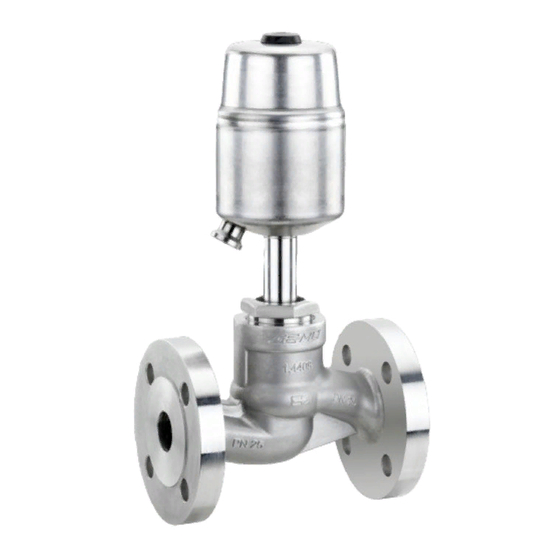
- Seite 1 Schrägsitzventil Metall, DN 10 - 80 Angle Seat Globe Valve Metal, DN 10 - 80 ORIGINAL EINBAU- UND MONTAGEANLEITUNG INSTALLATION, OPERATING AND MAINTENANCE INSTRUCTIONS...
-
Seite 2: Inhaltsverzeichnis
Inhaltsverzeichnis Allgemeine Hinweise Voraussetzungen für die einwandfreie Allgemeine Hinweise Funktion des GEMÜ-Ventils: Allgemeine Sicherheitshinweise 2 Sachgerechter Transport und Lagerung Hinweise für Service- Installation und Inbetriebnahme durch und Bedienpersonal eingewiesenes Fachpersonal Warnhinweise Bedienung gemäß dieser Einbau- und Verwendete Symbole Montageanleitung Begriff sbestimmungen Ordnungsgemäße Instandhaltung Vorgesehener Einsatzbereich Auslieferungszustand... -
Seite 3: Hinweise Für Service
Hinweise für Service- Warnhinweise und Bedienpersonal Warnhinweise sind, soweit möglich, nach folgendem Schema gegliedert: Die Einbau- und Montageanleitung enthält grundlegende Sicherheitshinweise, die bei SIGNALWORT Inbetriebnahme, Betrieb und Instandhaltung zu beachten sind. Nichtbeachtung kann zur Art und Quelle der Gefahr Folge haben: ®... -
Seite 4: Verwendete Symbole
Vorgesehener Verwendete Symbole Einsatzbereich Gefahr durch heiße Oberfl ächen! Das 2/2-Wege-Sitzventil GEMÜ 514 ist für den Einsatz in Rohrleitungen Gefahr durch ätzende Stoff e! konzipiert. Es steuert ein durchfl ießendes Medium indem es durch ein Steuermedium geschlossen oder Hand: Beschreibt allgemeine geöff... - Seite 5 Maximal zulässige Sitz Leckrate Sitzdichtung Norm Prüfverfahren Leckrate Prüfmedium PTFE DIN EN 1266-1 Luft Metall DIN EN 1266-1 Luft Nenn- Max. Betriebsdruck [bar] Steuerdruck [bar] weite Federkraft geschlossen Federkraft geschlossen Werte Antriebs- Antriebs- Antriebs- Antriebs- Antriebs- größe 0 größe 3 größe 1 größe 4 größe 2...
- Seite 6 Druck- / Temperatur-Zuordnung für Schrägsitz-Ventilkörper Zulässige Betriebsdrücke in bar bei Temperatur in °C* Werkstoff- Anschluss-Code Code 1, 3D, 9 (bis DN 50) 16,0 16,0 16,0 13,5 1, 9 (ab DN 65) 10,0 10,0 10,0 1, 9, 17, 37, 60, 3C, 3D 25,0 23,8 21,4...
-
Seite 7: Bestelldaten
** Nur Steuerfunktion NC Gewindeanschluss Gewindemuffe DIN ISO 228 Gewindemuffe BS 21 Rc Baulänge DIN 3202-4 Reihe M8 Gewindestutzen DIN ISO 228 GEMÜ 514 GEMÜ 514 Gewindemuffe NPT Antriebe Antriebe 3, 4 Baulänge DIN 3202-4 Reihe M8 0, 1, 2... -
Seite 8: Herstellerangaben
Herstellerangaben Funktionsbeschreibung Das fremdgesteuerte 2/2-Wege-Ventil Transport GEMÜ 514 ist ein Metall-Schrägsitzventil mit Durchgangskörper und besitzt einen Ventil nur auf geeignetem Lademittel robusten wartungsarmen Aluminium transportieren, nicht stürzen, vorsichtig Kolbenantrieb. Ventilkörper und Sitzdichtung handhaben. sind gemäß Datenblatt in verschiedenen Verpackungsmaterial entsprechend Ausführungen erhältlich. -
Seite 9: Montage Und Bedienung
Montage und Bedienung Installationsort: VORSICHT Vor Einbau: Ventil äußerlich nicht stark beanspruchen. Eignung Ventilkörper- und Dichtwerkstoff Installationsort so wählen, dass Ventil entsprechend Betriebsmedium prüfen. nicht als Steighilfe genutzt werden Siehe Kapitel 6 "Technische Daten". kann. Rohrleitung so legen, dass Schub- und 11.1 Montage des Ventils Biegungskräfte, sowie Vibrationen... -
Seite 10: Steuerfunktionen
Montage: 5. Ventilfl ansch und Rohrfl ansch mit 1. Eignung des Ventils für jeweiligen geeignetem Dichtmaterial und Einsatzfall sicherstellen. Das Ventil passenden Schrauben verbinden muss für die Betriebsbedingungen (Dichtmaterial und Schrauben sind nicht des Rohrleitungssystems (Medium, im Lieferumfang enthalten). Mediumskonzentration, Temperatur Schrauben über Kreuz anziehen! und Druck) sowie die jeweiligen Umgebungsbedingungen geeignet sein. -
Seite 11: Steuermedium Anschließen
11.3 Steuermedium anschließen Nur für Regelventile: Steuerfunktion 8 Wichtig: Beidseitig angesteuert Steuermediumleitungen (in Ruhestellung geöffnet) spannungs- und knickfrei Ruhezustand des Ventils: durch Federkraft montieren! geöffnet. Öffnen und Schließen des Ventils Je nach Anwendung geeignete durch Ansteuern der entsprechenden Anschlussstücke verwenden. Steuermediumanschlüsse (Anschluss 2: Öffnen / Anschluss 4: Schließen). -
Seite 12: Auswechseln Der Dichtungen
12.2 Auswechseln der Dichtungen Wichtig: Austausch der Stahl-Sitzdichtung nur durch GEMÜ. Komplettes Ventil mit ausgefüllter Rxxxx Rxxxx Rücksendeerklärung an GEMÜ senden. Ventilkörperkennzeichnung Ventilkörperkennzeichnung Durchgangskörper Eckkörper Wichtig: Dichtring 4 bei jeder Demontage / Typenschild Antrieb Ventilkörperkennzeichnung Montage des Antriebs RAxxx R002 austauschen. -
Seite 13: Inbetriebnahme
Inbetriebnahme Inspektion und Wartung WARNUNG WARNUNG Aggressive Chemikalien! Unter Druck stehende Armaturen! ® Verätzungen! ® Gefahr von schwersten Verletzungen Vor Inbetriebnahme Dichtheit oder Tod! der Medienanschlüsse Nur an druckloser Anlage arbeiten. prüfen! VORSICHT Dichtheitsprüfung nur mit geeigneter Heiße Anlagenteile! Schutzausrüstung. ®... -
Seite 14: Demontage
Demontage Hinweise Demontage erfolgt unter den gleichen Hinweis zur Mitarbeiterschulung: Vorsichtsmaßnahmen wie die Montage. Zur Mitarbeiterschulung nehmen Ventil demontieren (siehe Kapitel 12.1 Sie bitte über die Adresse auf der "Demontage Antrieb"). letzten Seite Kontakt auf. Leitungen des Steuermediums Im Zweifelsfall oder bei Missverständnissen abschrauben (siehe Kap. -
Seite 15: Fehlersuche / Störungsbehebung
Fehlersuche / Störungsbehebung Fehler Möglicher Grund Fehlerbehebung Steuermedium entweicht aus Entlüftungsbohrung (Anschluss 4* bei Antrieb austauschen und Steuermedium auf Steuerkolben undicht Steuerfunktion NO / Verschmutzungen untersuchen Anschluss 2* bei Steuerfunktion NC) Steuermedium entweicht Antrieb austauschen und Steuermedium auf Spindelabdichtung undicht aus Leckagebohrung* Verschmutzungen untersuchen Medium entweicht aus... -
Seite 16: Schnittbilder Und Ersatzteile
Schnittbilder und Ersatzteile Anschluss 4 / GEMÜ 514 mit Entlüftungsbohrung bei Steuerfunktion 2 (NO) Sitzdichtung aus PTFE Anschluss 2 / Entlüftungsbohrung bei Steuerfunktion 1 (NC) Leckagebohrung Pos. Benennung Bestellbezeichnung Ventilkörper K 514... Dichtring 514...SVS... Sitzdichtung Antrieb 9514 Überwurfmutter Spindel Ventilteller... -
Seite 17: Sitzdichtung Aus Stahl
Anschluss 4 / GEMÜ 514 mit Entlüftungsbohrung bei Sitzdichtung aus Stahl Steuerfunktion 2 (NO) Anschluss 2 / Entlüftungsbohrung bei Steuerfunktion 1 (NC) Leckagebohrung Pos. Benennung Bestellbezeichnung Ventilkörper K 514... Dichtring 514...SVS... Antrieb 9514 Überwurfmutter Spindel Ventilteller 17 / 40... -
Seite 18: Einbauerklärung
29.12.2009 Projektnummer: SV-Pneum-2009-12 Handelsbezeichnung: Typ 514 Es wird erklärt, dass die folgenden grundlegenden Anforderungen der Maschinenrichtlinie 2006/42/EG erfüllt sind: 1.1.3.; 1.1.5.; 1.1.7.; 1.2.1.; 1.3.; 1.3.2.; 1.3.3.; 1.3.4.; 1.3.7.; 1.3.9.; 1.5.3.; 1.5.5.; 1.5.6.; 1.5.7.; 1.5.8.; 1.5.9.; 1.6.5.; 2.1.1.; 3.2.1.; 3.2.2.; 3.3.2.; 3.4.4.; 3.6.3.1.; 4.1.2.1.; 4.1.2.3.; 4.1.2.4.; 4.1.2.5.; 4.1.2.6. a); 4.1.2.6. b);... -
Seite 19: Eu-Konformitätserklärung
GEMÜ Gebr. Müller Apparatebau GmbH & Co. KG Fritz-Müller-Straße 6-8 D-74653 Ingelfingen erklären, dass unten aufgeführte Armaturen die Sicherheitsanforderungen der Druckgeräte- richtlinie 2014/68/EU erfüllen. Benennung der Armaturen - Typenbezeichnung Sitzventil GEMÜ 514 Benannte Stelle: TÜV Rheinland Berlin Brandenburg Nummer: 0035 Zertifi kat-Nr.:... - Seite 38 38 / 40...
- Seite 39 39 / 40...
- Seite 40 GEMÜ Gebr. Müller Apparatebau GmbH & Co. KG · Fritz-Müller-Str. 6-8 · D-74653 Ingelfi ngen-Criesbach Telefon +49(0)7940/123-0 · Telefax +49(0)7940/123-192 · info@gemue.de · www.gemu-group.com...