Gemü 514 Originalbetriebsanleitung
Vorschau ausblenden
Andere Handbücher für 514:
- Original einbau- und montageanleitung (44 Seiten) ,
- Montageanleitung (40 Seiten) ,
- Betriebsanleitung (28 Seiten)

Verwandte Anleitungen für Gemü 514


Inhaltszusammenfassung für Gemü 514
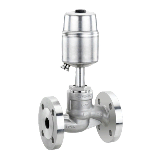
- Seite 1 Schrägsitzventil Metall, DN 10 - 80 Angle Seat Globe Valve Metal, DN 10 - 80 ORIGINALBETRIEBSANLEITUNG OPERATING INSTRUCTIONS 514_us...
-
Seite 2: Inhaltsverzeichnis
Inhaltsverzeichnis Allgemeine Hinweise Allgemeine Hinweise Voraussetzungen für die einwandfreie Funk- Allgemeine Sicherheitshinweise 2 tion des GEMÜ-Ventils: Hinweise für Service- und Sachgerechter Transport und Lagerung. Bedienpersonal Installation und Inbetriebnahme durch Warnhinweise eingewiesenes Fachpersonal. Verwendete Symbole Bedienung gemäß dieser Begriff sbestimmungen Betriebsanleitung. Vorgesehener Einsatzbereich Ordnungsgemäße Instandhaltung. -
Seite 3: Hinweise Für Service- Und
Hinweise für Service- und Warnhinweise Bedienpersonal Warnhinweise sind, soweit möglich, nach folgendem Schema gegliedert: Die Betriebsanleitung enthält grundlegende Sicherheitshinweise, die bei Inbetriebnahme, SIGNALWORT Betrieb und Instandhaltung zu beachten sind. Nichtbeachtung kann zur Folge haben: Art und Quelle der Gefahr ® Mögliche Folgen bei Nichtbeachtung. Gefährdung von Personen durch Maßnahmen zur Vermeidung der elektrische, mechanische und chemische... -
Seite 4: Verwendete Symbole
Verwendete Symbole Vorgesehener Einsatzbereich Das 2/2-Wege-Sitzventil GEMÜ 514 Gefahr durch heiße Oberfl ächen! ist für den Einsatz in Rohrleitungen konzipiert. Es steuert ein durchfl ießendes Medium indem es durch ein Gefahr durch ätzende Stoff e! Steuermedium geschlossen oder geöff net werden kann. -
Seite 5: Technische Daten
Technische Daten Betriebsmedium Steuermedium Aggressive, neutrale, gasförmige und flüssige Medien, die Neutrale Gase die physikalischen und chemischen Eigenschaften des Max. zul. Temperatur des Steuermediums: 60° C jeweiligen Gehäuse- und Dichtwerkstoffes nicht negativ beeinflussen. Füllvolumen: Antriebsgröße 0 und 3: 0,05 dm³ Antriebsgröße 1 und 4: 0,125 dm³... - Seite 6 Betriebsdruck-/Steuerdruckkennlinien Antriebsgröße 1 / Federkraft geöffnet (NO) Antriebsgröße 1 / Beidseitig angesteuert (DA) min. Steuerdruck in Abhängigkeit vom Betriebsdruck min. Steuerdruck in Abhängigkeit vom Betriebsdruck Betriebsdruck [bar] Betriebsdruck [bar] Antriebsgröße 2 / Federkraft geöffnet (NO) Antriebsgröße 2 / Beidseitig angesteuert (DA) min.
-
Seite 7: Bestelldaten
Gewindemuffe NPT flüssigen Medien um „Wasserschläge“ zu vermeiden Baulänge DIN 3202-4 Reihe M8 Flansch Flansch EN 1092 / PN25 / Form B GEMÜ 514 GEMÜ 514 Baulänge siehe Körpermaße Antriebe 0, 1, 2, 5 Antriebe 3, 4 Flansch ANSI Klasse 125/150 RF Baulänge siehe Körpermaße... -
Seite 8: Herstellerangaben
Herstellerangaben Funktionsbeschreibung Das fremdgesteuerte 2/2-Wege-Ventil GEMÜ Transport 514 ist ein Metall-Schrägsitzventil mit Durch- gangskörper und besitzt einen robusten Ventil nur auf geeignetem Lademittel wartungsarmen Aluminium Kolbenantrieb. transportieren, nicht stürzen, vorsichtig Ventilkörper und Sitzdichtung sind gemäß handhaben. Datenblatt in verschiedenen Ausführungen Verpackungsmaterial entsprechend erhältlich. -
Seite 9: Montage Und Anschluss
11 Montage und Anschluss Montagearbeiten nur durch geschultes Fachpersonal. Vor Einbau: Geeignete Schutzausrüstung gemäß Ventilkörperwerkstoff und Sitzdichtung den Regelungen des Anlagenbetreibers entsprechend Betriebsmedium auslegen. berücksichtigen. Eignung vor Einbau prüfen! Siehe Kapitel 6 "Technische Daten". Installationsort: VORSICHT 11.1 Montage des Ventils Ventil äußerlich nicht stark beanspruchen. - Seite 10 Die Durchfl ussrichtung ist durch einen Flanschanschluss Pfeil auf dem Ventilkörper gekennzeichnet: Ventil im angelieferten Zustand einbauen: 1. Auf saubere und unbeschädigte Dichtfl ächen der Anschlussfl ansche achten. 2. Flansche vor Verschrauben sorgfältig ausrichten. 3. Dichtungen gut zentrieren. 4. Alle Flanschbohrungen nutzen. 5.
-
Seite 11: Steuerfunktionen
11.2 Steuerfunktionen Anschluss 4 Folgende Steuerfunktionen sind verfügbar: Steuerfunktion 1 Federkraft geschlossen (NC): Ruhezustand des Ventils: durch Federkraft Anschluss 2 geschlossen. Ansteuern des Antriebs (An- schluss 2) öff net das Ventil. Entlüften des Antriebs bewirkt das Schließen des Ventils durch Federkraft. Steuerfunktion 2 Federkraft geöff... -
Seite 12: Steuermedium Anschließen
11.3 Steuermedium anschließen 12 Montage / Demontage von Ersatzteilen Wichtig: Steuermediumleitungen span- Siehe auch Kapitel 11.1 "Montage des Ventils" nungs- und knickfrei montieren! und Kapitel 20 "Schnittbilder und Ersatzteile". Je nach Anwendung geeignete Anschlussstücke verwenden. 12.1 Demontage Antrieb und Dichtring 4 Gewinde des Steuermediumanschlusses: G1/4 1. -
Seite 13: Auswechseln Der Sitzdichtung
12.2 Auswechseln 12.3 Montage Antrieb der Sitzdichtung und Dichtring 4 1. Antrieb A demontieren wie in Kapitel 1. Antrieb A in Off en-Position bringen. 12.1, Punkte 1-4 beschrieben. 2. Neuen Dichtring 4 in Ventilkörper 1 2. Tellerscheibe d an der Spindel b lösen einlegen. -
Seite 14: Inbetriebnahme
13 Inbetriebnahme 14 Inspektion und Wartung WARNUNG WARNUNG Aggressive Chemikalien! Unter Druck stehende Armaturen! ® Verätzungen! ® Gefahr von schwersten Verletzungen Vor Inbetriebnahme Dichtheit oder Tod! der Medienanschlüsse Nur an druckloser Anlage arbeiten. prüfen! Dichtheitsprüfung nur mit ge- VORSICHT eigneter Schutzausrüstung. Heiße Anlagenteile! VORSICHT ®... -
Seite 15: Demontage
15 Demontage 18 Hinweise Demontage erfolgt unter den gleichen Hinweis zur EG-Maschinen- Vorsichtsmaßnahmen wie die Montage. richtlinie 2006/42/EG: Ventil demontieren (siehe Kapitel 12.1 Eine Einbauerklärung gemäß EG- "Demontage Antrieb und Dichtring 4"). Maschinenrichtlinie 2006/42/EG Leitung des Steuermediums abschrauben liegt dem Produkt bei. (siehe Kapitel 11.3 "Steuermedium Beim Einbau in eine als anschließen"). -
Seite 16: Fehlersuche / Störungsbehebung
19 Fehlersuche / Störungsbehebung Fehler Möglicher Grund Fehlerbehebung Steuermedium entweicht aus Entlüftungsbohrung (An- Antrieb austauschen und Steuermedium auf schluss 4* bei Steuerfunktion Steuerkolben undicht Verschmutzungen untersuchen 1 (NC) / Anschluss 2* bei Steuerfunktion 2 (NO)) Steuermedium entweicht Antrieb austauschen und Steuermedium auf Spindelabdichtung undicht aus Leckagebohrung* Verschmutzungen untersuchen... -
Seite 17: Schnittbilder Und Ersatzteile
20 Schnittbilder und Ersatzteile GEMÜ 514 mit Sitz- dichtung aus PTFE Anschluss 4 / Entlüftung bei Steuerfunktion 1 Anschluss 2 / Entlüftung bei Steuerfunktion 2 Leckagebohrung Pos. Benennung Bestellbezeichnung Ventilkörper K 514... Dichtring 514...SVS... Sitzdichtung Antrieb 9514 Überwurfmutter Spindel Ventilteller... -
Seite 18: Gemü 514 Mit Sitzdichtung Aus Stahl
GEMÜ 514 mit Sitz- dichtung aus Stahl Anschluss 4 / Entlüftung bei Steuerfunktion 1 Anschluss 2 / Entlüftung bei Steuerfunktion 2 Leckagebohrung Pos. Benennung Bestellbezeichnung Ventilkörper K 514... Dichtring 514...SVS... Antrieb 9514 Überwurfmutter Spindel Ventilteller 514_us 18 / 40... -
Seite 19: Eg-Konformitätserklärung
GEMÜ Gebr. Müller GmbH & Co. KG Fritz-Müller-Straße 6-8 D-74653 Ingelfi ngen erklären, dass unten aufgeführte Armaturen die Sicherheitsanforderungen der Druckgeräte- richtlinie 97/23/EG erfüllen. Benennung der Armaturen - Typenbezeichnung Sitzventil GEMÜ 514 Benannte Stelle: TÜV Rheinland Berlin Brandenburg Nummer: 0035 Zertifi kat-Nr.: 01 202 926/Q-02 0036 Konformitätsbewertungsverfahren:... - Seite 40 VENTIL-, MESS- UND REGELSYSTEME VALVES, MEASUREMENT AND CONTROL SYSTEMS GEMÜ Gebr. Müller Apparatebau GmbH & Co. KG · Fritz-Müller-Str. 6-8 · D-74653 Ingelfi ngen-Criesbach Telefon +49(0)7940/123-0 · Telefax +49(0)7940/123-192 · info@gemue.de · www.gemue.de...