Fujitsu FUTRO S400 Kurzanleitung
Inhaltsverzeichnis
Verfügbare Sprachen
Verfügbare Sprachen
Kapitel
Inhaltsverzeichnis

Verwandte Anleitungen für Fujitsu FUTRO S400


Inhaltszusammenfassung für Fujitsu FUTRO S400
- Seite 2 Are there ..any technical problems or other questions you need clarified? Please contact: ● our Hotline/Help Desk (see the Help Desk list or go to: www.fujitsu-siemens.com/support/helpdesk.html) ● your sales partner ● your sales outlet Further information can be found in the "Safety" manual.
- Seite 4 Dieses Handbuch wurde erstellt von Xerox Global Services. This manual was published by Xerox Global Services. Herausgegeben von/Published by Fujitsu Siemens Computers GmbH Printed in the Federal Republic of Germany AG 08/07 Ausgabe/Edition 2 Bestell-Nr./Order No.: A26361-K522-Z123-1-7419...
-
Seite 7: Inhaltsverzeichnis
Inhalt Ihr FUTRO S400........................... 1 Darstellungsmittel......................... 1 CE-Kennzeichnung ........................1 Energiesparen, Entsorgung und Recycling .................. 1 Anschlüsse und Anzeige ........................2 Gerät aufstellen ............................ 3 Geräte anschließen ..........................3 Bildschirm anschließen ........................ 3 Maus anschließen ........................3 Tastatur anschließen........................4 Gerät an das Netzwerk (LAN) anschließen .................. - Seite 8 Inhalt Deutsch A26361-K522-Z123-1-7419, Ausgabe 2...
-
Seite 9: Ihr Futro S400
Ihr FUTRO S400... …ist ein universeller Netzwerk-Client. Das intelligente und flexible Terminal ist zuverlässig und leicht zu warten. Der Thin Client benötigt keine Lüfter und keine Festplatte. Dadurch ist er besonders leise im Betrieb. Das Betriebssystem ist auf einem Compact Flash installiert. -
Seite 10: Anschlüsse Und Anzeige
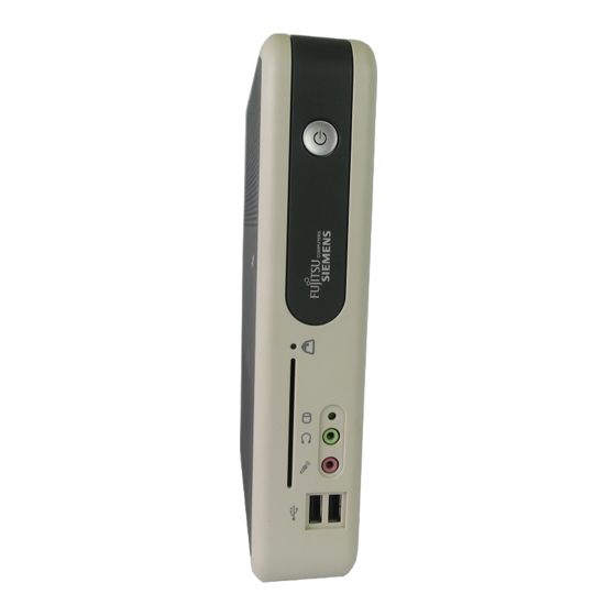
Kurzbeschreibung Anschlüsse und Anzeige Für den Anschluss von peripheren Geräten wie Maus, Tastatur oder Chipkartenleser stehen Ihnen an Vorder- und Rückseite des Geräts folgende Schnittstellen zur Verfügung. Vorderansicht Rückansicht Ein-/Ausschalter RJ45-LAN-Anschluss (Local Area Network) Betriebsanzeige 10 = Einbauplatz für Module Anzeige für SmartCard-Leser 11 = PS/2-Mausanschluss SmartCard-Leser... -
Seite 11: Gerät Aufstellen
Kurzbeschreibung Die Anschlüsse finden Sie an Vorder- und Rückseite des Geräts. Welche Anschlüsse an Ihrem Gerät verfügbar sind, hängt davon ab, welche Ausbaustufe Sie gewählt haben. Die Standardanschlüsse sind durch die nachfolgenden oder durch ähnliche Symbole gekennzeichnet. Tastaturanschluss PS/2-Mausanschluss Serielle Schnittstelle Parallele Schnittstelle/Drucker Bildschirmanschluss Kopfhörer... -
Seite 12: Tastatur Anschließen
Kurzbeschreibung USB-Maus anschließen ► Schließen Sie die USB-Maus an den USB-Anschluss des Geräts an. Tastatur anschließen Standard-Tastatur anschließen Verwenden Sie nur die mitgelieferte Tastaturleitung. ► Stecken Sie den rechteckigen Stecker der Tastaturleitung in die rechteckige Buchse an der Unterseite oder an der Rückseite der Tastatur. ►... -
Seite 13: Externe Geräte An Die Parallele Oder Serielle Schnittstelle Anschließen
Kurzbeschreibung Leitungen anschließen ► Alle betroffenen Geräte ausschalten. ► Die Netzstecker aller betroffenen Geräte aus den Schutzkontakt-Steckdosen ziehen. ► Alle Leitungen am Gerät und an den Peripheriegeräten stecken. Beachten Sie auf jeden Fall die Sicherheitshinweise im Kapitel "Wichtige Hinweise". ► Alle Datenübertragungsleitungen in die vorgesehenen Steckvorrichtungen der Daten-/Fernmeldenetze stecken. -
Seite 14: Externe Geräte An Die Usb-Schnittstellen Anschließen
Kurzbeschreibung Externe Geräte an die USB-Schnittstellen anschließen An die USB-Schnittstellen können Sie eine Vielzahl externer Geräte anschließen (z. B. Drucker, Scanner, Modem oder Tastatur). USB-Geräte sind hot-plug-fähig. Daher können die Leitungen von USB-Geräten bei eingeschaltetem System angeschlossen und gelöst werden. Weitere Informationen finden Sie in der Dokumentation zu den USB-Geräten. -
Seite 15: Konfiguration
Kurzbeschreibung Konfiguration BIOS-Setup aufrufen ► Wenn das System startet, drücken Sie (eventuell mehrmals) die Taste Del / Entf . Das BIOS-Setup wird gestartet. Sie erreichen weitere Einstellmöglichkeiten im BIOS-Setup, wenn Sie eines der Register auswählen. PXE-Systemstart ► Wenn Sie das Gerät mit dem Ein-/Ausschalter eingeschaltet haben, drücken Sie beim Start des Systems (eventuell mehrmals) die Taste F12 . - Seite 16 Kurzbeschreibung Folgende Einstellungen sind möglich: Network Boot Protocol: PXE (Standard) oder RPL Angabe des verwendeten Systemstart- Protokolls. Boot Order: Int 19h Es wird immer zuerst das Netzwerk gestartet, bevor die lokalen Geräte aktiviert werden. PnP/ BEV (BBS) Wenn ein BBS-BIOS (BIOS Boot Specification) vorhanden ist, wird das System durch das BBS- BIOS gestartet.
-
Seite 17: Systemerweiterungen
Kurzbeschreibung Systemerweiterungen Optional können Sie folgende Komponenten einbauen: ● eine PCI-Baugruppe (Länge maximal 155 mm) ● ein Modul Es kann sinnvoll sein, wenn Sie sich einige Teile dieses Kapitels ausdrucken, da das Gerät beim Ein-/Ausbau von Systemerweiterungen ausgeschaltet sein muss. Eventuell ist für eine Systemerweiterung oder Hardware-Hochrüstung ein Update des BIOS notwendig. -
Seite 18: Gehäuse Öffnen
Kurzbeschreibung Gehäuse öffnen Wenn Sie Ihr System erweitern möchten, müssen Sie zuerst das Gehäuse öffnen. ► Schalten Sie das Gerät aus. ► Ziehen Sie den Netzstecker aus der Schutzkontakt-Steckdose. ► Ziehen Sie alle Leitungen vom Gerät. ► Ziehen Sie das Gerät aus dem Standfuß heraus und legen Sie es waagerecht auf eine feste Oberfläche. -
Seite 19: Smartcard-Leser Einbauen
Kurzbeschreibung ► Schieben Sie das Gerät von vorne nach hinten in den Standfuß, bis dieser auf der rechten Seite einrastet. ► Stecken Sie alle zuvor entfernten Leitungen. SmartCard-Leser einbauen Sie können, sofern nicht bereits vorhanden, einen SmartCard-Leser einbauen. SmartCard-Leser an Halterung befestigen ►... -
Seite 20: Smartcard-Leser Ausbauen
Kurzbeschreibung ► Schließen Sie die Leitung am Stecker (1) auf dem Mainboard an und führen Sie sie, wie in der Abbildung dargestellt (2). ► Schließen Sie das Gehäuse (siehe "Gehäuse schließen"). Achten Sie darauf, dass die Leitungen nicht zwischen Gehäuse und Bauteilen eingeklemmt werden! SmartCard-Leser ausbauen ►... -
Seite 21: Pci-Baugruppe Einbauen
Kurzbeschreibung PCI-Baugruppe einbauen Sie können nur PCI-Baugruppen mit einer maximalen Länge von 150 mm einbauen. ► Nehmen Sie auf der PCI-Baugruppe die erforderlichen Einstellungen vor. ► Öffnen Sie das Gehäuse (siehe "Gehäuse öffnen"). ► Entfernen Sie die Risercard (1). ► Lösen Sie die Schraube (2), um den dahinter liegenden Riegel zu entfernen. - Seite 22 Kurzbeschreibung ► Befestigen Sie die Schrauben (4) und gegebenenfalls (3), um die PCI-Baugruppe an der Rückseite des Geräts zu fixieren. Manche PCI-Baugruppen haben keine Öffnung für die Schraube (3). In diesem Fall befestigen Sie die PCI-Baugruppe nur mit der Schraube (4). ►...
-
Seite 23: Pci-Baugruppe Ausbauen
Kurzbeschreibung PCI-Baugruppe ausbauen ► Öffnen Sie das Gehäuse (siehe "Gehäuse öffnen"). ► Lösen Sie die Schrauben (4) und gegebenenfalls (3). ► Lösen Sie die Schraube (2), um die PCI- Baugruppe zu entfernen. ► Ziehen Sie die Risercard mit der angesteckten PCI-Baugruppe aus dem Einbauplatz heraus (1) und nehmen Sie sie aus dem Gehäuse. -
Seite 24: Module Ein- Und Ausbauen
Kurzbeschreibung ► Stecken Sie die Risercard wieder in ihren Steckplatz (1). ► Befestigen Sie den Riegel mit der Schraube (2). ► Bauen Sie die Rückseitenabdeckung wieder ein, indem Sie diese von innen in den Einbauplatz setzen und mit den Schrauben (3) und (4) an der Rückseite des Geräts befestigen. - Seite 25 Kurzbeschreibung ► Drücken Sie das Modul vorsichtig bis zum Anschlag in Pfeilrichtung (1). ► Befestigen Sie das Modul mit den Schrauben (2) an der Blechhalterung. ► Schließen Sie das Gehäuse (siehe "Gehäuse schließen"). Modul mit direktem Mainboard-Stecker (z. B. DVI-Modul) ausbauen ►...
- Seite 26 Kurzbeschreibung Modul ohne direkten Mainboard-Stecker (z. B. WLAN-Modul) einbauen ► Öffnen Sie das Gehäuse (siehe "Gehäuse öffnen"). ► Lösen Sie die Schrauben (1) und nehmen Sie die Abdeckung des Einbauplatzes heraus. Werfen Sie die Abdeckung des Einbauplatzes nicht weg. Wenn Sie das Modul wieder entfernen, müssen Sie die Abdeckung des Einbauplatzes wegen der Kühlung, des Brandschutzes und der einzuhaltenden EMV-Vorschriften (Vorschriften zur lektromagnetischen Verträglichkeit) wieder einbauen.
- Seite 27 Kurzbeschreibung ► Schließen Sie die Leitung am Stecker (1) auf dem Mainboard an und führen Sie sie, wie in der Abbildung dargestellt (2). ► Schließen Sie das Gehäuse (siehe "Gehäuse schließen"). Achten Sie darauf, dass die Leitungen nicht zwischen Gehäuse und Bauteilen eingeklemmt werden! Modul ohne direkten Mainboard-Stecker (z.
-
Seite 28: Lithium-Batterie Tauschen
Kurzbeschreibung Lithium-Batterie tauschen Damit die Systeminformation dauerhaft gespeichert werden kann, ist eine Lithium-Batterie eingebaut, die den CMOS-Speicher mit Strom versorgt. Wenn die Spannung der Batterie zu niedrig oder die Batterie leer ist, wird eine entsprechende Fehlermeldung ausgegeben. Die Lithium-Batterie muss dann ausgetauscht werden. -
Seite 29: Technische Daten
Kurzbeschreibung Technische Daten Elektrische Daten Prozessor: AMD MX 1500 Nennspannungsbereich: 90 V - 265 V Abmessungen Breite/Tiefe/Höhe: 50 mm/180 mm/247 mm Gewicht im Grundausbau: ca. 1,6 kg (mit Standfuß) Umgebungsbedingungen Temperatur: ● Betrieb 15 °C ..35 °C ● Transport -25 °C ..