DOSIERGERÄT 8035 1 EINFÜHRUNG Sehr geehrter Kunde, Lesen Sie diese Bedienungsanleitung 1.3 Sicherheitshinweise gründlich, bevor Sie das Gerät montieren und in Betrieb nehmen. Bürkert stellt verschiedene Durchfluss- Sensoren her. Jeder kann in einer Vielzahl von Applikationen eingesetzt werden. 1.1 Auspacken und Kontrolle Gerne beraten wir hierzu intensiv.
DOSIERGERÄT 8035 2 BESCHREIBUNG 2.1 Bestell-Nummern, Dosiergerät SE35 Das Dosiergerät 8035 ist auf einem Elektronikmodul SE35 und einem Fitting S030 Inline aufgebaut. Alle Informationen betreffend Fittings S030 Inline befinden sich in der entsprechender Bedienungsanleitung. das Fitting S030 muss seaprat bestellt werden.
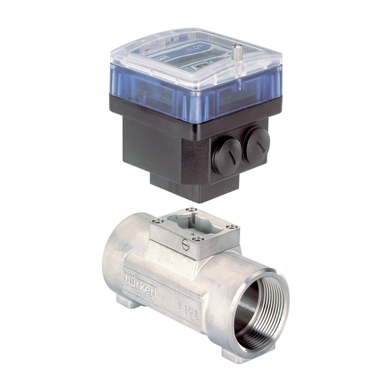
DOSIERGERÄT 8035 2 BESCHREIBUNG 2.2 Aufbau und Messprinzip Aufbau Das Dosiergerät 8035 besteht aus einem Für die einwandfreie Arbeitsweise der Kunststoffgehäuse (PC) IP65 direkt auf Schaltelektronik ist eine Spannungs- das Fitting S030, durch Schnellverschluss, versorgung von 12-30 VDC (zusätzliche montiert. Das Gehäuse enthält die 115/230 VAC Option) erforderlich.
Seite 6
DOSIERGERÄT 8035 2 BESCHREIBUNG 2.3 Dosiergerät 8035 Inline Abmessungen (mm) Die Größe H ist von dem Anschluss-Typ und Werkstoff des Fittings unabhängig. Fig. 1 Dosiergerät 8035 Abmessungen D-6-...
DOSIERGERÄT 8035 2 BESCHREIBUNG 2.4 Technische Daten Rohrdurchmesser DN6 bis DN65 Umgebung Umgebungs- und 0 bis 60 °C Lagertemperatur Relative Feuchtigkeit max 80 %, nicht kondensierend Schutzart IP 65 Durchflussmessung Messbereich 0.3 bis 10 m/s Messgenauigkeit 1. Mit anlagespezifischer Kalibrierung oder Teach-In: ≤...
DOSIERGERÄT 8035 3 INSTALLATION 3.1 Allgemeine Hinweise zum Einbau - Das Dosiergerät 8035 kann nur für Messungen von reinen, flüssigen, wasserähnlichen Medien verwendet werden (Festanteil max: 1%, Viskosität max. 300 cSt ). - Das Gerät ist nicht für die Dosierung von Gasen geeignet.
DOSIERGERÄT 8035 3 INSTALLATION 3.3 Elektrischer Anschluss 3.3.1 Allgemeine Hinweise zum elektrischen Anschluss Das Gerät darf nicht bei angeschlossenem Netzkabel geöffnet werden. Es ist ratsam, Sicherheitsvorrichtungen zu installieren: Stromversorgung: Sicherung (250 mA) und ein Schalter. Relais: Höchstens 3 A-Sicherung und Überlastschalter (je nach Anwendung).
DOSIERGERÄT 8035 3 INSTALLATION Prinzip einer Äquipotentialität: Versorgung 12-30VDC Metallische Rohre diese Verbindung wird an die Elektronikplatine ausgeführt Versorgung 12-30VDC Geräte wie Ventil, Pumpe, usw... Kunststoffrohre diese Verbindung wird an die Elektronikplatine ausgeführt (*) ist keine direkte Erdung möglich, schließen Sie einen 100 nF/50V-Kondensator zwischen dem negativen Anschluss der Versorgungsquelle und der Erde an.
3 INSTALLATION DOSIERGERÄT 8035 3.3.2 Einsatz der Kabelschellen Bevor Sie das Gerät verkabeln, fädeln Sie die mitgelieferten Kabelschellen in Elektronikplatine bzw. 115/230 VAC-Versorgungsplatine, wenn vorhanden, ein. Fig. 3 Einsatz der Kabelschellen 3.3.3 Einstellung der Schalter SENSOR INPUT bzw. SENSOR SUPPLY Bevor Sie das Gerät verkabeln, überprüfen Sie bitte die korrekte Einstellung der beiden...
Bei dieser Ausführung kann die Spannungsversorgung des Dosiergeräts für die Binäreingänge IN1 bis IN4 und den Ausgang OUT verwendet werden: In diesem Fall wird Klemme 6 (COMMON) an Klemme 9 (L-) verbunden. Fig. 4 Anschluss des 8035, 12-30 VDC. D-13-...
Seite 14
3A/230VAC FLOW SENSOR Sicherung Anschluss der 115/230 VAC Anschluss Relais 2 Anschluss Relais 1 Versorgungsspannung (siehe Beispiel Fig. 4) (siehe Beispiel Fig. 4) Relais-Kabel obligatorisch mittels mitgelieferten kabelschellen befestigen (siehe § 3.3.2) Fig. 5 Anschluss des 8035, 115/230 VAC. D-14-...
Das Testmenü bietet dem Benutzer die Möglichkeit, die Binäreingänge (Fernsteuerung) zu überprüfen und die Arbeitsweise der Relais zu simulieren. Mit Hilfe dieses Menüs kann die Rotationsfrequenz des Schaufelrades gemessen werden. 4.1 Bedien- und Anzeigeelemente des Dosiergerätes 8035 Inkrementiertaste Bestätigungs-taste Zahlenwert je Stelle Eingabe und Menü-...
DOSIERGERÄT 8035 4 BEDIENUNG 4.2 Beschreibung der verschiedenen Dosieroptionen Die Dosieroptionen werden im Untermenü «OPTION» des Kalibriermenüs ausgewählt (siehe § 4.4.4). 4.2.1 Option «LOK.HAND» Bei Wahl dieser Option wird die Meldung «BATCH M» im Hauptmenü angezeigt. Hierdurch kann eine mit Hilfe der Tastatur zu definierende Menge dosiert werden (siehe §...
Anzeige Supply 12..30Vdc Dosiergerät 8035 INLINE Die Auswahl der zu dosierenden Menge aus dem Speicher (von 1 bis 7) erfolgt durch Codierung mit Hilfe der Binäreingänge IN1, IN2 und IN3. Die nachstehende Tabelle gibt den Zustand jedes einzelnen Eingangs entsprechend dem gewünschten Volumen (Menge)
DOSIERGERÄT 8035 4 KONFIGURIERUNG 4.2.5 Option «EXT.[T]» Mit dieser Option kann die Dosierung einer Menge gesteuert werden, die sich proportional zur Aktivierungsdauer des Binäreingangs 1 verhält (siehe § 4.3.3). Die Proportionalität gestaltet sich wie folgt: X= dosierende Menge = (A x t) + B A: Proportionalitätskoeffizient (l/s,...)
DOSIERGERÄT 8035 4 KONFIGURIERUNG 4.3 Hauptmenü Im Hauptmenü werden folgende Größen angezeigt: Dosierung im manuellen Betriebsmodus (siehe § 4.3.1). BATCH M Erscheint nur, wenn die Dosieroption «LOK.HAND» oder «MEM+HAND» im Kalibriermenü gewählt wurde (siehe Kalibriermenü § 4.4). Dosierung im automatischen Betriebsmodus (siehe § 4.3.2).
DOSIERGERÄT 8035 4 KONFIGURIERUNG 4.3.2 Dosierung im automatischen Betriebsmodus (Option «LOK.MEM», «MEM+HAND» oder «EXT.MEM») Mit Hilfe des automatischen Betriebsmodus kann die Dosierung einer der 7 zuvor in die Bibliothek eingegebenen Mengen vorgenommen werden. Die Dosierung kann entweder mit Hilfe der Tastatur oder über die Binäreingänge gesteuert werden.
1 2 3 4 5 6 7 8 9 10 11 Anzeige Supply 12..30Vdc Dosiergerät 8035 INLINE Fig. 6 Anschlussbeispiel Meldung «ALARM» während des Dosiervorgangs: Dosierproblem (siehe § 5.1). Während der Dosierung der gewählten Menge können der Durchfluss angezeigt, eine Pause eingelegt, ein Reset vorgenommen oder die Dosierung beendet werden, jedoch nur mit Hilfe der Tastatur (siehe §...
DOSIERGERÄT 8035 4 KONFIGURIERUNG 4.3.5 Funktion Pause/Reset Ein Dosiervorgang kann momentan oder endgültig gestoppt werden (aber nicht bei der Option EXT [T]). a) Optionen MEM+HAND, LOK.MEM, LOK.HAND: Die aktuelle Countdown des ENTER ENTER WEITER Dosierung wird laufenden fortgeführt Dosierwertes Das Gerät ist für...
DOSIERGERÄT 8035 4 BEDIENUNG ENTER 4.4 Kalibriermenü: gleichzeitig während 5 s drücken. In diesem Menü werden folgende Größen programmiert: SPRACHE Wahl der Sprache der einzelnen Meldungen (deutsch, englisch, französisch, italienisch). Wahl der Maßeinheit für das zu dosierende Volumen, die EINHEIT Durchfluss- und die Totalisatorenanzeige.
DOSIERGERÄT 8035 4 BEDIENUNG 4.4.2 Einheiten ENTER ENTER ENTER m LITRE EINHEIT BATCH LIT/SEC LITRE LIT/MIN LIT/H 0..9 US GAL M3/MIN IMP GAL M3/H USGAL/S USGAL/M USGAL/H IMPGAL/S IMPGAL/M IMPGAL/H ENTER TOTAL ENTER LITRE US GAL IMP GAL ENTER K-FAKTOR Hinweis: Die Rückkehr in das Hauptmenü...
Seite 25
DOSIERGERÄT 8035 4 BEDIENUNG 4.4.3 K-Faktor In diesem Menü wird der K-Faktor der Armatur eingegeben (siehe Bedienungsanleitung Fitting S030). Mit dem "Teach in", kann aber der K-Faktor, spezifisch zu den Applikationsbedigungen, praktisch ermittelt werden. Dazu muss der Benutzer nur eine bekannte Menge durch seine Anlage fließen lassen.
Seite 26
DOSIERGERÄT 8035 4 BEDIENUNG V7 = 00000 OPTION LOK.MEM V1 = 00000 ENTER ENTER 0..9 0..9 V1 = 00100 V7 = 00700 ENTER UBERL. JA ENTER LOK.HAND ENTER UBERL. JA MEM + HAND V1 = 00000 V7 = 00000 ENTER 0..9...
DOSIERGERÄT 8035 4 KONFIGURIERUNG 4.4.5 Überlaufkorrektur Mit dem Dosiergerät 8035 INLINE kann eine Überlaufkorrektur vorgenommen werden. Sie besteht aus der Speicherung der Flüssigkeitsmenge, die noch nach dem Schließen des Ventils abläuft, damit diese von der nachfolgenden Dosierung abgezogen werden kann.
4 KONFIGURIERUNG DOSIERGERÄT 8035 4.4.7 Relais Das Gerät verfügt über 2 Relais: - Das Relais 1 steuert ausschließlich die Öffnung des Hauptventils (großer Durchfluss). Eine Aktivierungsverzögerung kann festgelegt sowie die Wirkungsrichtung umgekehrt werden, wobei der Benutzer den Prozentsatz der zu dosierenden Menge einprogrammieren kann, der durch das Hauptventil (großer Durchfluss) laufen muss.
Seite 29
DOSIERGERÄT 8035 4 KONFIGURIERUNG RELAIS 1 VER = RELAIS ENTER ENTER 0..9 VER = 020 ENTER 0..9 INV NEIN 85 % ENTER INV JA ENTER ALARM INV NEIN RELAIS 2 ENTER ENTER INV JA TOTAL ENTER END DOSI INV NEIN...
DOSIERGERÄT 8035 4 KONFIGURIERUNG 4.4.8 Totalisator Gleichzeitige Rückstellung der 2 Totalisatoren. Sie erfolgt endgültig, sobald der Benutzer die Enter-Taste bei der Option «ENDE» im Kalibriermenü betätigt. TOTAL RES NEIN ENTER RES JA ENDE ENTER ENTER 4.5 Testmenü: gleichzeitig während 5 s drücken.
DOSIERGERÄT 8035 4 KONFIGURIERUNG Option «EXT[T]» Der Benutzer kann an dieser Stelle die an das Dosiergerät abgegebene Pulsdauer überprüfen. ENTER EXT.STEU 0.00 SEC ..SEC 5.35 SEC Abgabe eines Impulsende Impulses ENTER RELAIS 1 4.5.2 Überprüfung der Arbeitsweise der Relais Bei dieser Option kann der Benutzer die Relais mit Hilfe der Tastatur betätigen, um ihre...
DOSIERGERÄT 8035 5 WARTUNG 5.1 Fehlermeldungen 5.1.1 Meldung «ALARM» MELDUNG "ALARM" WÄHREND EINER DOSIERUNG Die Meldung «ALARM» erscheint während des Dosiervorgangs (unabhängig von der Dosieroption), falls das bzw. die Ventile geöffnet sind und das Dosiergerät keinen Durchfluss ermittelt. Die Auslösezeit des Alarms wird im Kalibriermenü festgelegt (siehe Abs.
Seite 33
5 WARTUNG DOSIERGERÄT 8035 b) Dosierung über die Binäreingänge, durch EXT[T] aktiviert: Das Gerät ist für eine neue RESET ALARM Dosierung bereit (siehe 4.3.3) "Weiter" kann nur mittels der Tastatur gewählt werden. WEITER Die aktuelle Dosierung wird fortgeführt (**) Bei den Optionen EXT.MEM und EXT [T] kann auch die Taste ENTER gedrückt werden.
Sind Installation und Einsatzbedingungen korrekt, benötigt das Dosiergerät keine besondere Wartung. Bei Ablagerungen kann der eingetauchte Teil des Sensors (Schaufelrad, Achse, Lager) mit Wasser oder einem für PVDF geeigneten Reinigungsmittel gereinigt werden. 5.3 Basis Einstellungen des 8035 bei Auslieferung Sprache: Englisch Überlaufkorrektur: Alarm WÄHREND: Ein, VER1 = 100...
1 INTRODUCTION BATCH CONTROLLER 8035 1.3 User's Responsibility for Safety Before installing or mounting this device, please take our advice and read the entire manual thoroughly. Bürkert manufactures a broad range of flow sensors. While each of these products is...
2 SPECIFICATION 2.1 Ordering codes for electronic module SE35 Batch The batch controller 8035 is consisting of a S030 fitting which houses the paddle-wheel and an electronic controller SE35, specially designed to be installed on the fitting. Use a separate order N° for the S030 Fitting. For more informations about the fittings see the corresponding instruction manual.
(S030). ("EXT . [T]") (§ 4.3.3) The controller 8035 Batch is mounted on a pipe in series with the valve. The 8035 unit measures the flow, calculates the volumes, and operates the valve(s) according to the selected program (see §...
Seite 43
2 DESCRIPTION BATCH CONTROLLER 8035 2.3 Batch Controler 8035 INLINE external dimensions (mm) The height H is independant from the connection type and material of the fitting. Fig. 1 Batch Controler 8035 INLINE external dimensions E-5-...
2 SPECIFICATION BATCH CONTROLLER 8035 2.4 Technical Data Pipe diameter DN6 to DN65 Environment Ambient and storage 0 to 60 °C temperature Relative humidity max 80 %, non condensated Flow rate measurement Measuring range 0.3 to 10 m/s Measuring error 1.
Seite 45
2 SPECIFICATION BATCH CONTROLLER 8035 Medium Pressure class PN 10 or PN16, depending on fitting material, see also temperature/pressure diagram, § 3.1 Max. medium temperature PVC: 50°C PP, PVDF, stainless steel, brass: 100°C Max. viscosity 300 cSt. Max. solid particle rate...
3 INSTALLATION BATCH CONTROLLER 8035 Installation Guidelines The batch controller 8035 can only be used to measure pure, liquid and water ressembling fluids (solids content ≤ 1%, viscosity max. 300 cSt with on-line calibration). The device is not suited for dosing gases.
BATCH CONTROLLER 8035 3 INSTALLATION 3.3 Electrical Connection 3.3.1 Electrical connection recommendations Do not open and wire the device with the power supply connected. It is advisable to put security devices on : Power supply: Fuse (300 mA) and an interrupter Relay: 3A max.
Seite 48
3 INSTALLATION BATCH CONTROLLER 8035 Realizing (principle) the equipotentiality: Power supply 12-30VDC Metallic pipes connection to be made on the connection strip of the electronic board Power supply 12-30VDC Metallic devices (valve, pump, etc) Plastic pipes connection to be made on...
3 INSTALLATION BATCH CONTROLLER 8035 3.3.2 How to use the cable clips Before wiring the device, insert the supplied cable clips into the cuts of the electronic board and, if fitted, into the cut of the 115/230 VAC power supply board.
(see § 3.3.2) This version enables the controller power supply to be used for inputs IN1 to IN4 and output OUT: in that case, connect terminal 6 (COMMON) to terminal 9 (L-). Fig. 4 Electrical wiring 8035, 12-30 VDC version E-12-...
Connect relay 1 Connect relay 2 power supply (see ex. fig. 4) (see ex. fig. 4) Relay cables must be fitted here to the board using the supplied cable clips (see § 3.3.2) Fig. 5 Electrical wiring 8035, 115/230 VAC version E-13-...
4 OPERATION BATCH CONTROLLER 8035 The operation is classified according to three levels. A) Display This menu allows the user to control the dosing by the keypad (start, pause, reset, stop); using the LCD display, he can monitor the flow rate and the initial preset volume throughout the dosing operation.
4 CONFIGURATION BATCH CONTROLLER 8035 4.2 Description of Dosing Options Dosing options are selected within the «OPTION» sub-menu of the Calibration Menu. ( § 4.4.4.) 4.2.1. «LOC.MANU» Option» When this option is selected, the prompt «BATCH M» is displayed within the main menu. It enables the generation of a volume which can be defined using the keypad.
4 CONFIGURATION BATCH CONTROLLER 8035 4.2.4 »EXT.MEM» Option Generation of a volume previously entered into the memory (7 in total) from a remote position by using the binary data inputs (See § 4.2.2.). The following example describes the various methods of connection.
4 CONFIGURATION BATCH CONTROLLER 8035 4.2.5. «EXT. [T]» Option Delvery of a volume proportional to the duration of the high level on the input 1 (see § 4.3.3.). The proportional relationship is as follows: X = Volume = (A x t) +B A Coefficient of proportionality (/s;...) B Offset (l;...)
4 CONFIGURATION BATCH CONTROLLER 8035 4.3 Main menu Within the main menu, following readouts are available: Dosing in manual mode (see § 4.3.1.). BATCH M Only available if the «LOC.MEM» or the «MEM+MANU» Options have been selected within the Calibration menu (see § 4.4) Dosing in automatic mode (see §...
Seite 57
4 CONFIGURATION BATCH CONTROLLER 8035 4.3.2. Dosing in automatic mode («LOC.MEM», «MEM+MANU», or «EXT.MEM» Options) Generation of the volume from one of the 7 values previously entered into the memory. The selected volume can be initiated either from the keypad or by the binary inputs.
4 CONFIGURATION BATCH CONTROLLER 8035 4.3.3. Dosing proportional to a pulse duration («EXT.[T]» Option) This option enables the initiation of a dosing volume proportional to the time during which binary data input 1 is enabled. The following prompts are displayed within the principal menu during the dosing operation.
4 CONFIGURATION BATCH CONTROLLER 8035 4.3.5. Pause / reset function A current dosage can be momentarily or definitively stopped (except mode EXT [T]). a) Modes MEM+MANU, LOC.MEM, LOC.MANU: Current batch Countdown of the ENTER CONTINUE ENTER dosage operation in continues...
4 CONFIGURATION BATCH CONTROLLER 8035 ENTER 4.4. Calibration Menu: pressing simultaneously for 5 seconds Within this menu, the following parameters may be set: Choice of language used for prompts (German, English, French, LANGUAGE Italian, etc.) Choice of measurement unit used for volume, flow rate and UNIT counters.
4 CONFIGURATION BATCH CONTROLLER 8035 4.4.2 Unit ENTER ENTER ENTER m LITER UNIT BATCH LIT/SEC LITER LIT/MIN LIT/H 0..9 US GAL M3/MIN IMP GAL M3/H UGAL/SEC UGAL/MIN UGAL/H IGAL/SEC IGAL/MIN IGAL/H ENTER TOTAL ENTER LITER US GAL IMP GAL ENTER K-FACTOR Note: Return to the main menu is only available from the «TOTAL»...
4 CONFIGURATION BATCH CONTROLLER 8035 Note: The device uses the last K-factor entered or determined . K-FACTOR ENTER TEACH N ENTER 000.00 Entering of K-factor as specified in the charts. 0..9 K = 046.60 OPTION ENTER 0000.0 TEACH O END DOSE...
Seite 63
4 CONFIGURATION BATCH CONTROLLER 8035 V7 = 00000 OPTION LOC.MEM V1 = 00000 ENTER ENTER 0..9 0..9 V1 = 00100 V7 = 00700 ENTER OVERFILL ENTER LOC.MANU ENTER OVERFILL MEM + MANU V1 = 00000 V7 = 00000 ENTER 0..9 0..9...
BATCH CONTROLLER 8035 4.4.5. Overfill correction The 8035 Batch controller has an overfill correction facility. It memorises the fluid volume which flows after the closure of the valve so that this volume can be deducted from the next batch. In this sub-menu the user enables or disables the overfill correction facility.
BATCH CONTROLLER 8035 4.4.7. Relays The 8035 Batch controller provides 2 relays: - Relay 1 controls the opening of the main valve (high flow rate). A delay before activation may be selected and the operating polarity may be inverted; the user also has the facility of setting the percentage of the selected volume to be delivered through the main valve (high flow rate).
Seite 66
4 CONFIGURATION BATCH CONTROLLER 8035 RELAY RELAY 1 DEL = ENTER ENTER 0..9 DEL = 020 ENTER 0..9 INV NO 85 % ENTER INV YES ENTER ALARM INV NO RELAY 2 ENTER ENTER INV YES TOTAL ENTER END DOSE INV NO...
4 CONFIGURATION BATCH CONTROLLER 8035 4.4.8 Totalizer Simultaneous setting of both counters to zero. This facility becomes operational when the user presses the ENTER key while in the «END» option within the Calibration menu. TOTAL RES NO ENTER RES YES...
4 CONFIGURATION BATCH CONTROLLER 8035 «EXT. [T] Option In this option, the user can check the pulse duration being sent to the 8035 Batch controller. ENTER EXT.ACT. 0.00 SEC ..SEC 5.35 SEC Start of pulse End of pulse...
5 MAINTENANCE BATCH CONTROLLER 8035 5.1 Fault prompts 5.1.1. «ALARM» prompt "ALARM" PROMPT DURING A DOSAGE The «ALARM « prompt will be displayed during a dosage operation (irrespective of the dosage option) if one or both valves are open but the controller does not detect any flow.
Seite 70
5 MAINTENANCE BATCH CONTROLLER 8035 c) Dosage through Binary Inputs and activated by EXT.MEM : Device ready for a new ALARM RESET batch (see 4.3.3) Choice "Continue" can only be made on keypad. Current batch CONTINUE continues (**) When in mode EXT.MEM or EXT [T], you can also press the Enter key on the keypad.
5.2. Transducer maintenance In correct installation conditions, the 8035 Batch controller is maintenance free. If clogging occurs, the immersed parts of the sensor can be cleaned with water or any other cleaning agent suitable for use with PVDF.
5 MAINTENANCE BATCH CONTROLLER 8035 5.4. Spare Parts List Position Specification Order code Complete housing 425248 Cover with lid, screws and window 553189 Electronic board + protective plate + Mounting instruction sheet 553171 Cover with lid, screws, front plate and electronics...
Seite 75
4.5.3 Affichage de la fréquence du capteur ....................F-30 MAINTENANCE ......................F-31 Messages d'erreur ..............................F-31 Entretien du capteur ............................F-33 Configuration des contrôleurs de dosage 8035 à la livraison ..............F-33 Liste des pièces de rechange ........................... F-35 ANNEXE ........................F-36 Abaque débit/vitesse/diamètre ......................... F-36 Certificat de conformité...
1 INTRODUCTION CONTROLEUR DE DOSAGE 8035 Cher client, 1.3 Consignes de sécurité Nous vous recommandons de lire attentivement la présente notice d'emploi avant la mise en service. Bürkert commercialise une large gamme de capteurs de débit. Comme chacun de ces produits est conçu pour fonctionner dans...
CONTROLEUR DE DOSAGE 8035 2.1 Références de commande du contrôleur de dosage 8035 Le contrôleur de dosage 8035 est composé d'une électronique SE35 montée sur un raccord S030 Inline. Toutes les informations relatives aux raccords Inline se trouvent dans la notice correspondante.
CONTROLEUR DE DOSAGE 8035 2 DESCRIPTION 2.2 Construction et principe de mesure Construction Mode de fonctionnement Le contrôleur de dosage 8035 se compose Le contrôleur de dosage 8035 peut d'un boîtier électronique SE35 en fonctionner en : polycarbonate IP65 directement monté par quart de tour (baïonnette) sur le raccord...
2 DESCRIPTION CONTROLEUR DE DOSAGE 8035 2.3 Dimensions (mm) La hauteur H est indépendante du type de raccord et du matériau. Fig. 1 Contrôleur de dosage 8035 dimensions externes F-5-...
CONTROLEUR DE DOSAGE 8035 2 SPECIFICATION 2.4 Caractéristiques techniques Diamètre des conduites DN6 à DN65 Environnement Température ambiante 0 à 60 °C et de stockage Humidité relative max 80 %, non condensée Mesure du débit Echelle de mesure 0.3 à 10 m/s Erreur de mesure 1.Avec calibration sur site ou "Teach-In":...
Seite 81
2 SPECIFICATION CONTROLEUR DE DOSAGE 8035 Fluide Classe de pression PN10 ou PN16, fonction du matériau du raccord, voir le diagramme température/pression au § 3.1 Température max. du fluide PVC : 50°C PP : 80 °C PVDF, acier inoxydable, laiton : 100°C Viscosité...
CONTROLEUR DE DOSAGE 8035 3 INSTALLATION 3.1 Consignes de montage - Le contrôleur de dosage 8035 est uniquement adapté à la mesure de débit dans des fluides propres (particules solides ≤ 1%, viscosité max. 300 cSt avec étalonnage sur site).
3 INSTALLATION CONTROLEUR DE DOSAGE 8035 3.3 Raccordement électrique 3.3.1 Consignes de raccordement électrique Ne pas ouvrir, ne pas câbler l'appareil sous tension. Il est recommandé d‘utiliser des dispositifs de sécurité pour: Alimentation: un fusible (250mA) et un interrupteur Relais: un fusible 3A max. et un coupe circuit (selon l‘application).
Seite 84
CONTROLEUR DE DOSAGE 8035 3 INSTALLATION Schémas de principe d'une équipotentialité : Alimentation Conduites métalliques 12-30VDC liaison à réaliser sur le bornier de la carte électronique Alimentation 12-30VDC Appareils tels que vanne, pompe,... Conduites plastiques liaison à réaliser sur le bornier de la carte électronique...
3 INSTALLATION CONTROLEUR DE DOSAGE 8035 3.3.2 Mise en place des serre-câbles Avant de câbler l'appareil, insérer les serre-câbles fournis dans les encoches de la carte électronique et, si elle existe de la carte alimentation 115/230 VAC. Fig. 3 Mise en place des serre-câbles 3.3.3 Utilisation des interrupteurs SENSOR INPUT et SENSOR SUPPLY...
3 INSTALLATION CONTROLEUR DE DOSAGE 8035 3.3.4 Raccordement électrique, version 12-30 VDC Avant de démarrer le câblage électrique, lire attentivement les § 3.3.1, 3.3.2 et 3.3.3. Soulever le rabat transparent après avoir desserré la vis. Dévisser les 4 vis puis retirer le couvercle du contrôleur, passer les câbles à...
3 INSTALLATION CONTROLEUR DE DOSAGE 8035 3.3.5 Raccordement électrique, version 115/230 VAC - Avant de démarrer le câblage électrique, lire attentivement les § 3.3.1, 3.3.2 et 3.3.3. - Dans cette version il n'est pas possible d'utiliser l'alimentation du contrôleur pour les entrées IN1 à IN4 et la sortie OUT.
CONTROLEUR DE DOSAGE 8035 4 CONFIGURATION La programmation se fait suivant 3 menus. A) Menu principal Permet à l'utilisateur le dosage manuel par les touches du clavier (départ, pause, reset, arrêt). Affiche les valeurs du débit, du totalisateur principal, du totalisateur journalier, et le volume initial du dosage, durant les opérations de dosage.
CONTROLEUR DE DOSAGE 8035 4 CONFIGURATION 4.2 Options de dosage Les options de dosage sont sélectionnées dans le sous-menu "OPTION" du menu calibration (voir §4.4.4). 4.2.1 Option "LOC.MANU" Permet d'effectuer le dosage d'une quantité à définir à partir des touches du clavier (voir §...
CONTROLEUR DE DOSAGE 8035 4 CONFIGURATION 4.2.4 Option "EXT.MEM" Permet de commander à distance par l'intermédiaire des entrées binaires, le dosage d'un volume préalablement saisi en mémoire (V1 à V7) (voir §4.2.2). Affichage du menu principal.: Valeur du totalisateur sélectionné (Si le volume sélectionné = 0) ou bien: Volume de dosage sélectionné...
4 CONFIGURATION CONTROLEUR DE DOSAGE 8035 4.2.5 Option "EXT . [T]" Permet de commander le dosage d'un volume proportionnel à une durée d'activation sur l'entrée binaire 1 (voir § 4.3.3). La relation de proportionnalité est la suivante: X = Volume à doser = (A x t) + B A : coefficient de proportionalité...
CONTROLEUR DE DOSAGE 8035 4 CONFIGURATION 4.3 Menu principal Dans le menu principal, les grandeurs suivantes sont affichées: Dosage en mode manuel (voir § 4.3.1). BATCH M Apparaît uniquement si l'option de dosage "LOC.MANU" ou "MEM+MANU" a été sélectionnée dans le menu calibration (cf §4.4).
4 CONFIGURATION CONTROLEUR DE DOSAGE 8035 4.3.2 Dosage en mode automatique (option "LOC.MEM", "MEM+MANU" ou "EXT.MEM") Le mode automatique permet d'effectuer le dosage d'un des 7 volumes préalablement saisis en bibliothèque. Le dosage peut être commandé soit par les touches du clavier, soit par les entrées binaires.
CONTROLEUR DE DOSAGE 8035 4 CONFIGURATION 4.3.3 Dosage proportionnel à une durée d'impulsion (option "EXT. [T]") Pour commander le dosage d'un volume proportionnel à la durée d'activation de l'entrée binaire 1. Les messages suivants sont affichés dans le menu principal durant le dosage: Incrémentation du...
4 CONFIGURATION CONTROLEUR DE DOSAGE 8035 4.3.4 Affichage du débit et du volume initial pendant le dosage Pour afficher le débit et le volume initial pendant le dosage, presser brièvement la touche (quelle que soit l'option de dosage en cours).
CONTROLEUR DE DOSAGE 8035 4 CONFIGURATION ENTER 4.4 Menu calibration: pression simultanée pendant 5 s. Dans ce menu, les grandeurs suivantes sont programmées: LANGUE Choix de la langue des messages (allemand, anglais, français, italien, espagnol). Choix de l'unité pour le volume à doser, l'affichage du débit et UNITE les totalisateurs.
Seite 97
4 CONFIGURATION CONTROLEUR DE DOSAGE 8035 4.4.2 Unité ENTER ENTER ENTER m LITRE UNITE DOSAGE LIT/SEC LIT/MIN LITRE LIT/H 0..9 US GAL M3/MIN IMP GAL M3/H USGAL/S USGAL/M USGAL/H IMPGAL/S IMPGAL/M IMPGAL/H ENTER TOTAL ENTER LITRE US GAL IMP GAL ENTER FACT .
Seite 98
4 CONFIGURATION CONTROLEUR DE DOSAGE 8035 4.4.3 Facteur-K Saisie du facteur-K selon DN et matériau du raccord (voir manuel du raccord Inline S030). La fonction "Teach in", permet de déterminer expérimentalement le facteur-K, en faisant circuler une quantité connue de liquide dans l'installation.
Seite 99
4 CONFIGURATION CONTROLEUR DE DOSAGE 8035 OPTION V7 = 00000 LOC.MEM V1 = 00000 ENTER ENTER 0..9 0..9 V1 = 00100 V7 = 00700 ENTER CORREC J ENTER LOC.MANU ENTER CORREC J MEM + MANU V1 = 00000 V7 =...
4 CONFIGURATION 4.4.5 Correction de jetée Le contrôleur de dosage 8035 permet de mémoriser la quantité de fluide qui s'écoule encore après fermeture de la vanne afin de la retrancher du dosage suivant. C'est dans ce sous-menu que l'utilisateur active ou désactive la correction de jetée.
4 CONFIGURATION 4.4.7 Relais Le contrôleur de dosage 8035 est équipé de 2 relais: a) Le relais 1 réservé à l'ouverture de la vanne principale (grand débit). La temporisation, le sens de fonctionnement et le pourcentage de la quantité à doser devant passer par la vanne principale sont programmables.
Seite 102
CONTROLEUR DE DOSAGE 8035 4 CONFIGURATION RELAIS 1 DEL = RELAIS ENTER ENTER 0..9 DEL = 020 ENTER 0..9 INV NON 85 % ENTER INV OUI ENTER ALARME INV NON RELAIS 2 ENTER ENTER INV OUI TOTAL ENTER FIN DOSA...
4 CONFIGURATION CONTROLEUR DE DOSAGE 8035 4.4.8 Totalisateur Remise à zéro simultanée des 2 totalisateurs. Effective lorsque l'utilisateur appuie sur la touche ENTER de l'option "FIN" dans le menu calibration. TOTAL RES NON ENTER RES OUI ENTER ENTER 4.5 Menu test: pression simultanée pendant 5 s.
CONTROLEUR DE DOSAGE 8035 4 CONFIGURATION Option "EXT [T]" Permet de contrôler la durée de l'impulsion reçue par le contrôleur de dosage (cf § 4.2.5). ENTER EXT.CMDE 0.00 SEC ..SEC 5.35 SEC Envoi d'une Fin de...
5 MAINTENANCE CONTROLEUR DE DOSAGE 8035 5.1 Messages d'erreur 5.1.1 Message "ALARME" "ALARME" EN COURS DE DOSAGE Le message "ALARME" apparait en cours de dosage (quelle que soit l'option de dosage) si la ou les vannes sont ouvertes et que le contrôleur ne détecte aucun débit. Le délai de déclenchement de l'alarme est fixé...
Seite 106
5 MAINTENANCE CONTROLEUR DE DOSAGE 8035 c) Dosage par entrées binaires par EXT [T] : L'appareil permet un nouveau dosage ALARME RESET (voir 4.3.3) "Continu" ne peut être choisi qu'à partir du clavier. CONTINU Reprise du dosage en cours (**) Dans les modes EXT.MEM et EXT [T], vous pouvez également appuyer sur la touche Enter du clavier.
S030 (ailette, axe, paliers) peut être nettoyée avec de l'eau ou tout autre produit de nettoyage compatible avec le PVDF. 5.3 Configuration des contrôleurs de dosage 8035 à la livraison Alarme EN COURS : oui, DEL1 = 100 Langue:...
Seite 108
5 MAINTENANCE CONTROLEUR DE DOSAGE 8035 Configuration utilisateur contrôleur de dosage 8035 Langue: Alarme EN COURS : DEL1 = Unité débit: Alarme APRES dosage : DEL2 = Unité totalisateurs: Relais 1: DEL = Unité dosage: Facteur-K: inversion: Option de dosage: Relais 2: Volumes V1 à...
Seite 109
5 MAINTENANCE CONTROLEUR DE DOSAGE 8035 5.4 Pièces de rechange contrôleur de dosage 8035 Position Spécification Référence de commande Boîtier complet 425248 Couvercle à rabat en PC avec fenêtre et vis 553189 Carte électronique + plaque de protection + notice de montage 553171 Couvercle à...
Seite 112
CONTROLEUR DE DOSAGE 8035 Australia France Italy Singapore Burkert Contromatic Australia Pty. Ltd. Bürkert Contromatic Burkert Contromatic Italiana S.p.A. Burkert Contromatic Singapore Pte Ltd 2 Welder Road Rue du Giessen Centro Direzionale ‘Colombirolo’ 51 Ubi Avenue 1, #03-14 Seven Hills, NSW 2147...