4.4.3 Frequenzanzeige ..............................D-31 4.4.4 Durchfluss-Simulation ............................D-31 WARTUNG ............................D-32 Hinweis Störung..................................D-32 Basis Einstellung des 8035 bei Auslieferung ........................ D-32 Ersatzteil-Stückliste ................................D-33 ANHANG ............................D-34 Durchfluss-Diagramm (l/min, DN in mm und m/s) ......................D-34 Durchfluss-Diagramm (US-gallon/min, DN in inch und ft/s) ..................D-35 EG-Konformitäts-Erklärung ..............................F-35...
1 EINFÜHRUNG DURCHFLUSS-TRANSMITTER 8035 Sehr geehrter Kunde, 1.3 Sicherheitshinweise LESEN SIE DIESE BEDIENUNGS - Bürkert stellt verschiedene Transmitter her. ANLEITUNG GRÜNDLICH, BEVOR Jedes kann in einer Vielzahl von Applikatio- SIE DAS GERÄT MONTIEREN UND IN nen eingesetzt werden. Gerne beraten wir BETRIEB NEHMEN.
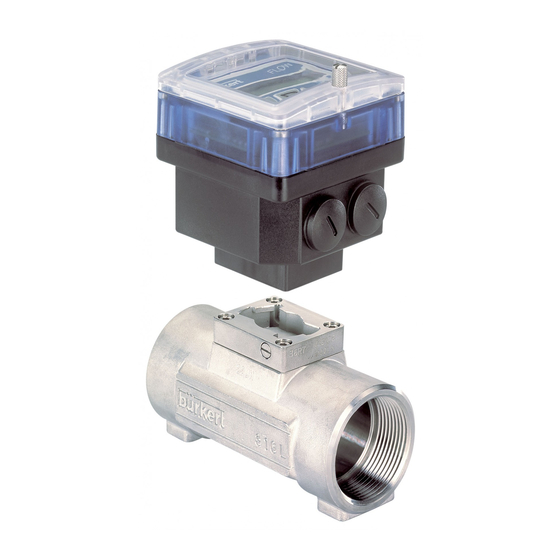
2 BESCHREIBUNG DURCHFLUSS-TRANSMITTER 8035 2.1 Bestell-Nummern Elektronikmodul SE35 Der Durchfluss-Transmitter 8035 besteht aus einem Elektronikmodul SE35, der auf einem Fitting S030 mit PVDF-Schaufelrad aufgebaut ist. Das Fitting S030 und das Elektronikmodul SE35 werden separat bestellt. Alle Informationen betreffend Fittings S030 befinden sich in der entsprechenden Bedie- nungsanleitung.
3-Leiter-Technik. Die Grenzwerte sind frei einstellbar. Der Durchfluss-Transmitter 8035 mit Pulsausgang-Sensor kann eine Durchfluss- menge ab 0,3 m/s Durchfluss geschwin- digkeit erfassen. Der Durchfluss-Transmitter 8035 mit Sinu- sausgang-Sensor kann eine Durchfluss- menge ab 0,5 m/s Durchfluss geschwin digkeit erfassen. D-5-...
2 BESCHREIBUNG DURCHFLUSS-TRANSMITTER 8035 2.4 Abmessungen (mm) (mm) Die Größe H ist von dem Anschluss-Typ und Werkstoff des Fittings unhabhängig. Fig. 2.1 Durchfluss-Transmitter Abmessungen D-6-...
2 BESCHREIBUNG DURCHFLUSS-TRANSMITTER 8035 2.5 Technische Daten Rohrdurchmesser DN6 bis DN65 Umgebungs Umgebungstemperatur 0 bis 60 °C (Betriebs- und Lager) Relative Feuchtigkeit max 80 %, nicht kondensierend Schutzart IP 65 Durchflussmessung Messbereich Sensor mit Pulsausgang: 0.3 bis 10 m/s Sensor mit Sinusaugang: 0.5 bis 10 m/s Messgenauigkeit 1.
Seite 8
2 BESCHREIBUNG DURCHFLUSS-TRANSMITTER 8035 Elektrische Daten Versorgungsspannung 12-30 VDC (V+) ± 10%, gefiltert u. geregelt, oder 115/230 VAC - 50/60 Hz (siehe technische Angaben 115/230 VAC unten) Umpolung geschützt Stromaufnahme Ohne Pulsausgangstromaufnahme: ≤ 70 mA Ausführung mit Relais ≤ 20 Ausführung ohne Relais Stromausgang 4...20 mA (3-Leitersystem Ausführung mit Relais;...
3 INSTALLATION DURCHFLUSS-TRANSMITTER 8035 3.1 Allgemeine Hinweise zum Einbau Der Transmitter 8035 Kompakt kann nur für Messungen von reinen, flüssigen, wasserähnlichen Medien verwendet werden (Feststoffanteil ≤ 1%, Viskosität max. 300 cSt mit On-Site- Kalibration). Das Gerät ist nicht für die Durchflussmessung von Gasen geeignet.
3 INSTALLATION DURCHFLUSS-TRANSMITTER 8035 3.2 Einbau Das Durchfluss-Transmitter-Elektronikmodul SE35 wird einfach mit spezifischen Fittings S030 in die Rohrleitung eingebaut. 1. Beim Einbau des Fittings 1 in die Rohr- leitung, müssen die Einbauvorschriften beachtet werden (siehe § 3.1 und in der Bedienungsanleitung des Fittings enthal- tene Einbauvorschriften).
3 INSTALLATION DURCHFLUSS-TRANSMITTER 8035 3.3 Elektrischer Anschluss 3.3.1 Allgemeine Hinweise zum elektrischen Anschluss Das Gerät darf nicht bei angeschlossenem Netzkabel geöffnet werden. Die Anlage des Gebäudes, in dem der Transmitter installiert ist, muss mit einem Schalter oder Überlastschalter gesichert sein. Dieser muss ganz nah an dem Transmitter, zugänglich und als Schaltvorrichtung...
Seite 12
3 INSTALLATION DURCHFLUSS-TRANSMITTER 8035 Kompakt-Ausführungen, Prinzipschaltbild einer Äquipotentialität: Versorgung 12-30VDC Metallische Rohre Versorgung 12-30VDC Geräte wie Ventil, Pumpe, usw... Kunststoffrohre (*) ist keine direkte Erdung möglich, schließen Sie einen 100 nF/50V-Kondensator zwischen dem negativen Anschluss der Versorgungsquelle und der Erde an.
3 INSTALLATION DURCHFLUSS-TRANSMITTER 8035 3.3.2 Elektrischer Anschluss Transmitter ohne Relais, mit EN 175301-803- Stecker Bevor Sie das Gerät verkabeln, lesen Sie bitte § 3.3.1 Aufbau des EN 175301-803-Steckers - Das Innenteil [3] aus dem Außenteil [2] herausnehmen. - Kabelverschraubung [5] aufschrauben.
3 INSTALLATION DURCHFLUSS-TRANSMITTER 8035 Anschluss des Elektronikmoduls SE35 mit EN 175301-803-Stecker an eine SPS Anschluss des 4-20 mA-Ausgangs des SE35 4-20 mA 300 mA 12-30 VDC Anschluss des Pulsausgangs des SE35, Anschluss des Pulsausgangs des SE35, verkabelt in NPN Modus...
3 INSTALLATION DURCHFLUSS-TRANSMITTER 8035 3.3.4 Einstellung des FLOW SENSOR-Schalters Bevor Sie das Gerät verkabeln, überprüfen Sie bitte die korrekte Einstellung der Schalter der Elektronikplatine. Ausgangssignal Schalter Transmitter des Durchfluss-Sensors 8035 Puls NPN Sirus (Spule) COIL 3.3.5 Elektrischer Anschluss Transmitter, 12-30 VDC, ohne Relais, mit Kabelverschraubungen Bevor Sie das Gerät verkabeln, lesen Sie bitte §...
Seite 16
3 INSTALLATION DURCHFLUSS-TRANSMITTER 8035 Anschluss des Elektronikmoduls SE35, 12-30 VDC, ohne Relais, mit Kabelver- schraubungen an eine SPS Anschluss des 4-20 mA-Ausgangs des SE35 4-20 mA 300 mA 12-30 VDC Without SOURCE SINK With Supply PULSE 12..30Vdc OUTPUT FLOW SENSOR...
3 INSTALLATION DURCHFLUSS-TRANSMITTER 8035 3.3.6 Elektrischer Anschluss Transmitter, 12-30 VDC, mit Relais und Kabelverschraubungen Bevor Sie das Gerät verkabeln, lesen Sie bitte § 3.3.1, 3.3.3 et 3.3.4 Schraube aufdrehen und durchsichtige Klappe heben. Schrauben aus der Frontanzeige herausdrehen und Deckel abnehmen. Anschließend Kabel durch die Kabel- verschraubungen ziehen und laut folgenden Anschlussplan anklemmen.
Seite 18
3 INSTALLATION DURCHFLUSS-TRANSMITTER 8035 Anschluss des Elektronikmoduls SE35, 12-30 VDC, mit Relais und Kabelver- schraubungen an eine SPS Der 4-20 mA-Ausgang des Transmitters 12-30 VDC mit Relais kann an eine SPS anges- chlossen werden. Entsprechend der SPS-Ausführung muss der Schalter [1] auf der Platine in Position "SOURCE"...
3 INSTALLATION DURCHFLUSS-TRANSMITTER 8035 3.3.7 Elektrischer Anschluss Transmitter, 115/230 VAC, ohne Relais, mit Kabelverschraubungen Bevor Sie das Gerät verkabeln, lesen Sie bitte § 3.3.1, 3.3.3 und 3.3.4 Schraube aufdrehen und durchsichtige Klappe heben. Schrauben aus der Frontanzeige herausdrehen und Deckel abnehmen. Anschließend Kabel durch die Kabel- verschraubungen ziehen und laut folgenden Anschlussplan anklemmen.
Seite 20
3 INSTALLATION DURCHFLUSS-TRANSMITTER 8035 Anschluss des Elektronikmoduls SE35, 115/230 VAC, ohne Relais, mit Kabelvers- chraubungen an eine SPS Anschluss des 4-20 mA-Ausgangs des SE35 4-20 mA Auswahl der Spannungsversorgung 115 VAC oder 230 VAC Without With Supply PULSE 12..30Vdc OUTPUT...
3 INSTALLATION DURCHFLUSS-TRANSMITTER 8035 3.3.8 Elektrischer Anschluss Transmitter, 115/230 VAC, mit Relais und Kabelverschraubungen Bevor Sie das Gerät verkabeln, lesen Sie bitte § 3.3.1, 3.3.3 und 3.3.4 Schraube aufdrehen und durchsichtige Klappe heben. Schrauben aus der Frontanzeige herausdrehen und Deckel abnehmen. Anschließend Kabel durch die Kabel- verschraubungen ziehen und laut folgenden Anschlussplan anklemmen.
Seite 22
3 INSTALLATION DURCHFLUSS-TRANSMITTER 8035 Anschluss des Elektronikmoduls SE35, 115/230 VAC, mit Relais und Kabelvers- chraubungen an eine SPS Der 4-20 mA-Ausgang des Transmitters 115/230 VAC mit Relais kann an eine SPS anges- chlossen werden. Entsprechend der SPS-Ausführung muss der Schalter [1] auf der Platine in Position "SOURCE"...
4 KONFIGURIERUNG DURCHFLUSS-TRANSMITTER 8035 Die Programmierung erfolgt unter Nutzung von 3 Menüs. Hauptmenü Hier werden der Durchfluss, der Ausgangsstrom, der Haupttotalisator und Tagestotalisator angezeigt. In diesem Menü wird auch der Tagestotalisator zurückgestellt Kalibriermenü Hier werden alle notwendigen Einstellungen (Sprache, Einheiten, K-Faktor, 4...20 mA Mess- bereich, Pulsausgang, Relais, Filter) durchgeführt.
4 KONFIGURIERUNG DURCHFLUSS-TRANSMITTER 8035 4.1 Beschreibung des Transmitters Programmiertasten Inkrementiertaste Zahlenwert je Stelle Bestätigungs-taste verändern von 0 bis 9 Eingabe und Menü- Menü durchlaufen punkte (Numerische Werte) Wahltaste Relais 1 Status Relais 2 Status Stelle auswählen Menü durchlaufen 4.2 Hauptmenü...
4 KONFIGURIERUNG DURCHFLUSS-TRANSMITTER 8035 ENTER 4.3 kalibriermenü: gleichzeitig während 5 Sekunden Im kalibriermenü werden folgende Grössen eingestellt: Auswahl der Sprache zwischen deutsch, englisch, französisch SPRACHE und italienisch. Auswahl der Einheit für die Durchfussanzeige und den Totalisator. EINHEIT Eingabe des K-Faktors aus Tabelle oder Teach-in Funktion zur K-FAKTOR Bestimmung des spezifischen K-Faktors.
4 KONFIGURIERUNG DURCHFLUSS-TRANSMITTER 8035 4.3.1 Sprache ENTER SPRACHE ENGLISH DEUTSCH Die gewünschte Sprache wird durch die Entertaste bestätigt und FRANCAIS dabei gleich aktiv. ITALIANO ENTER EINHEIT 4.3.2 Unité ENTER ENTER EINHEIT DURCHFLU LIT/SEC LIT/MIN LIT/H M3/MIN M3/H Der Durchfluss kann in jeder...
4 KONFIGURIERUNG DURCHFLUSS-TRANSMITTER 8035 4.3.3 K-Faktor In diesem Menü wird der K-Faktor des Fittings eingegeben (siehe Bedienungsanleitung S020). Mit dem "Teach in" , kann aber der K-Faktor, spezifisch zu den Applikationsbedigun- gen, praktisch ermittelt werden. Dazu muss der Benutzer nur eine bekannte Menge durch seine Anlage fliessen lassen.
4 KONFIGURIERUNG DURCHFLUSS-TRANSMITTER 8035 ENTER 4 = 0000 STROM Eingabe des Messbereichsanfang 0..9 ENTER 20 = 0000 4 = 0000 Eingabe des Messbereich- sende 0..9 ENTER 20 = 0180 PULS 4.3.5 Pulsausgang Er steht über einen Transistor, Open Kollektor zur Verfügung. In diesem Menü wird der Pulsausgang parametriert.
4 KONFIGURIERUNG DURCHFLUSS-TRANSMITTER 8035 4.3.8 Totalisator Hier werden der Haupt- und Tagestotalisator zurückgestellt. Die Rückstellung erfolgt erst wenn die Entertaste, bei der Stelle "ENDE" im Parametriermenü, gedrückt wird. ENTER RES NEIN TOTAL RES JA ENTER KODE ENTER 4.4 Testmenü: gleichzeitig während 5 Sekunden 0..9...
4 KONFIGURIERUNG DURCHFLUSS-TRANSMITTER 8035 4.4.2 Span-Abgleich Der Kunde hat hier die Möglichkeit die Grundeinstellung der 20 mA zu korrigieren. Der Verlauf ist identisch zum Offset. Wenn bei der Anzeige "SPAN" die Entertaste gedrückt wird, werden 20 mA vom Transmitter erzeugt. Stimmt dieser Wert nicht, kann er korrigiert werden in dem der gemessene Wert eingegeben wird.
Nach Drücken der Entertaste wird das Hauptmenü erreicht, aber das Gerät befindet sich in der Basis Einstellung (siehe § 5.2). Der Transmitter muss neu kalibriert werden. Sollte diese Meldung öfters erscheinen, schicken Sie das Gerät an Bürkert zurück. 5.2 Basis Einstellungen des 8035 bei Auslieferung 000.10 Sprache:...
1 INTRODUCTION FLOW TRANSMITTER 8035 BEFORE INSTALLING OR USING THIS PRODUCT, PLEASE READ THE ENTIRE MANUAL THOROUGHLY. This will enable you to fully profit from all of 1.3 User's Responsibility for Safety the advantages offered by this product. Bürkert manufactures a broad range of transmitters.
FLOW TRANSMITTER 8035 2.1 Ordering codes electronic module SE35 A flow transmitter 8035 consists of an S030 fitting which houses the paddle-wheel and an electronic transmitter SE35, specially designed to be installed on the fitting. The S030 fitting must be ordered separately. For more information about the fitting see the corresponding instruction manual.
FLOW TRANSMITTER 8035 2.3 Design and measuring principle Construction Measuring Principle The flow transmitter 8035 consists of an When liquid flows through the pipe, 4 electronic IP65 housing SE35 set by quar- magnets inserted in the paddle-wheel set ter turn on the fitting S030. The electronic...
2 DESCRIPTION FLOW TRANSMITTER 8035 2.4 Dimensions The height H is independant from the connection type and material of the fitting. Fig. 2.1 Dimensions of flow transmitter E-5-...
2 DESCRIPTION FLOW TRANSMITTER 8035 2.5 Technical data Pipe diameter DN6 to DN65 Environment Ambient temperature 0 to 60 °C (use and storage) Relative humidity max 80 %, non condensated Protection rating IP65 Flow rate measurement Measuring range Sensor with pulse output signal: 0.3 to 10 m/s Sensor with sinus output signal: 0.5 to 10 m/s...
2 DESCRIPTION FLOW TRANSMITTER 8035 Electrical features Power supply 12-30 VDC (V+) ± 10%, filtered and regulated, or 115/230 VAC - 50/60 Hz (see technical specifications 115/230 VAC below) Polarity reversal protected Current consumption Without consumption of pulse output: ≤...
3 INSTALLATION FLOW TRANSMITTER 8035 3.1 Installation Guidelines The compact transmitter 8035 can only be used to measure pure liquids ≤ (solids content 1%, viscosity max. 300 cSt with on-site calibration). The device is not suited for dosing gases. Pressure-Temperature-Diagram Mind pressure-temperature dependence according to the respective fitting materials.
3 INSTALLATION FLOW TRANSMITTER 8035 3.2 Installation The flow sensor electronic SE35 can be easily installed in pipes using the specially designed fitting system S030. 1. The fitting 1 must be installed into the pipe according to the installation speci- fications in section 3.1 and those of the...
3 INSTALLATION FLOW TRANSMITTER 8035 3.3 Electrical Connection 3.3.1 Electrical connection recommendations (all versions) Do not open and wire the device with the power supply connected. The electrical installation of the building where the transmitter is installed must be secured by a switch or a circuit breaker.
Seite 49
3 INSTALLATION FLOW TRANSMITTER 8035 Equipotentiality skeleton diagram of a compact version: Power supply 12-30VDC Metallic pipes Power supply 12-30VDC Metallic devices (valve, pump,...) Plastic pipes (*) If direct earthing is impossible, connect a 100 nF/50 V capacitor between the negative terminal and the earth.
3 INSTALLATION FLOW TRANSMITTER 8035 3.3.2 Electrical wiring of transmitter without relay, with cable plug EN 175301-8033 Before wiring the device, please read § 3.3.1 carefully. Assembly of the EN 175301-803 cable plug - Extract part [3] from part [2].
3 INSTALLATION FLOW TRANSMITTER 8035 Connection of electronic module SE35 with EN 175301-803 cable plug to a PLC Connection of the SE35 current output 4-20 mA 300 mA 12-30 VDC Connection of the SE35 pulse output, Connection of the SE35 pulse output,...
Pulse NPN Sinus (coil) COIL 3.3.5 Electrical wiring of transmitter 8035, 12-30 VDC, without relay, with cable glands Before wiring the device, please read § 3.3.1, 3.3.3 and 3.3.4 carefully. Lift the transparent lid after having unfastened the screw. Remove the cover of the device by unscrewing the 4 screws, pass the cables through the cable glands and connect according to the pin assignment below.
Seite 53
3 INSTALLATION FLOW TRANSMITTER 8035 Connection of electronic module SE35, 12-30 VDC, without relay, with cable glands to a PLC Connection of the SE35 cur- rent output 4-20 mA 300 mA 12-30 VDC Without SOURCE SINK With Supply PULSE 12..30Vdc...
3 INSTALLATION FLOW TRANSMITTER 8035 3.3.6 Electrical wiring of transmitter 8035, 12-30 VDC, with relays and cable glands Before wiring the device, please read § 3.3.1, 3.3.3 and 3.3.4 carefully. Lift the transparent lid after having unfastened the screw. Remove the cover of the device by unscrewing the 4 screws, pass the cables through the cable glands and connect according to the pin assignment below.
Seite 55
3 INSTALLATION FLOW TRANSMITTER 8035 Connection of electronic module SE35, 12-30 VDC, with relays and cable glands, to a PLC The 4-20 mA output of the transmitter, 12-30 VDC, with relays, can be connected to a PLC. Depending on the PLC type, position the "sourcing / sinking mode" switch [1] properly (see following fig.
3 INSTALLATION FLOW TRANSMITTER 8035 3.3.7 Electrical wiring of transmitter 8035, 115/230 VAC, without relay, with cable glands Before wiring the device, please read § 3.3.1, 3.3.3 and 3.3.4 carefully. Lift the transparent lid after having unfastened the screw. Remove the cover of the device by unscrewing the 4 screws, pass the cables through the cable glands and connect according to the pin assignment below.
Seite 57
3 INSTALLATION FLOW TRANSMITTER 8035 Connection of electronic module SE35, 115/230 VAC, without relay, with cable glands, to a PLC Connection of the SE35 current output 4-20 mA 115 VAC or 230 VAC selection switch Without With Supply PULSE 12..30Vdc...
3 INSTALLATION FLOW TRANSMITTER 8035 3.3.8 Electrical wiring of transmitter 8035, 115/230 VAC, with relays and cable glands Before wiring the device, please read § 3.3.1, 3.3.3 and 3.3.4 carefully. Lift the transparent lid after having unfastened the screw. Remove the cover of the device by unscrewing the 4 screws, pass the cables through the cable glands and connect according to the pin assignment below.
Seite 59
3 INSTALLATION FLOW TRANSMITTER 8035 Connection of electronic module SE35, 115/230 VAC, with relays and cable glands, to a PLC The 4-20 mA output of the transmitter, 115/230 VAC, with relays can be connected to a PLC. Depending on the PLC type, position the "sourcing / sinking mode" switch [1] properly (see following fig.
4 CONFIGURATION FLOW TRANSMITTER 8035 The operation of the 8025 is classified according to three levels. Main Menu This menu displays flow, output current, main totalizer and daily totalizer. The daily totalizer can also be reset in this menu.. Calibration Menu All the necessary settings, such as the language, engineering units, K-Factor, 4...20 mA...
4 CONFIGURATION FLOW TRANSMITTER 8035 4.1 Programming keys on the transmitter To scroll-up the menus Validate chosen or increase a value parameter or menu Relay 1 status To scroll-down the menus or Relay 2 status select a digit to be modified 4.2 Main Menu...
Seite 62
4 CONFIGURATION FLOW TRANSMITTER 8035 ENTER 4.3 Calibration Menu: press simultaneously for 5 seconds. The following variables can be set in the parameter definition menu: LANGUAGE Language selection between English, German, French and Italian. UNIT Selection of engineering units to display flow rate and totalizer.
4 CONFIGURATION FLOW TRANSMITTER 8035 4.3.1 Language ENTER LANGUAGE ENGLISH DEUTSCH The required language is confir- med and activated via the Enter- FRANCAIS key. ITALIANO ENTER UNIT 4.3.2 Engineering Units ENTER ENTER UNIT FLOW LIT/SEC LIT/MIN LIT/H M3/MIN M3/H The flow can be displayed in...
4 CONFIGURATION FLOW TRANSMITTER 8035 4.3.3 K-Factor The K-Factor of the fitting is entered in this menu (see manual of fitting S020). The "Teach in" function allows to practically detemine the application specific K-Factor. The user only needs to run a known quantity through his system.
4 CONFIGURATION FLOW TRANSMITTER 8035 ENTER 4 = 0000 CURRENT Entering the beginning of the measuring range 0..9 ENTER 20 = 0000 4 = 0000 Entering the end of the measuring range 0..9 ENTER 20 = 0180 PULSE 4.3.5 Pulse output The pulse output is available on the on open collector transistor.
4 CONFIGURATION FLOW TRANSMITTER 8035 4.3.8 Totalizer The main and daily totalizers are reset in this menu. The reset procedure only starts when Enter is pressed, at the "END" position in the parameter definition menu. ENTER RES NO TOTAL RES YES...
4 CONFIGURATION FLOW TRANSMITTER 8035 4.4.2 Span-compensation Here, the customer has the option to correct the basic adjustment of 20 mA. The procedure is identical to the Off-set procedure. When Enter is pressed while "SPAN" is indicated, the transmitter produces 20 mA. If this value is incorrect, it can be corrected by entering the measured value (within the limit of ±...
5 MAINTENANCE FLOW TRANSMITTER 8035 5.1 Trouble-shooting In correct installation the transmitters are maintenance-free. If contamination or clogging should occur during operation, the transmitter (paddle-wheel, bearing) can be cleaned with water or another appropriate cleaning agent. The message "ERROR" on the display indicates that calibration data has been lost.
Seite 75
4.4.4 Simulation d'un débit ............................F-30 MAINTENANCE ..........................F-31 Panne ....................................F-31 Configuration des transmetteurs 8035 à la livraison ....................F-31 Liste des pièces de rechange ............................F-32 ANNEXE .............................. F-33 Abaque débit/vitesse/diamètre (l/min, DN en mm et m/s) ...................F-33 Abaque débit/vitesse/diamètre (US-gallon/min, DN en inch et ft/s) .................F-34 Déclaration de conformité...
1 INTRODUCTION TRANSMETTEUR DE DEBIT 8035 Cher client, 1.3 Consignes de sécurité NOUS VOUS RECOMMANDONS DE LIRE ATTENTIVEMENT LA PRESENTE Bürkert commercialise une large gamme NOTICE D'EMPLOI AVANT LA MISE EN de transmetteurs de débit. Comme chacun SERVICE. de ces produits est conçu pour fonctionner dans une grande variété...
TRANSMETTEUR DE DEBIT 8035 2.1 Références de commande des modules électroniques SE35 Le transmetteur de débit 8035 se compose d'un module électronique SE35 monté sur un raccord S030 avec ailette en PVDF intégrée. Le raccord S030 doit être commandé séparément. Pour plus d'informations sur le raccord se référer à...
3-fils. Les valeurs des seuils et le sens de fonctionnement sont programma- bles. Le transmetteur de débit 8035 avec capteur à sortie impulsionnelle mesure le débit à partir d'une vitesse du fluide de 0,3 m/s. Le transmetteur de débit 8035 à sortie sinusoïdale mesure le débit à...
2 DESCRIPTION TRANSMETTEUR DE DEBIT 8035 2.4 Dimensions La hauteur H est indépen- dante du type de raccord et du matériau. Fig. 2.1 Dimensions transmetteur de débit F-5-...
2 DESCRIPTION TRANSMETTEUR DE DEBIT 8035 2.5 Caractéristiques techniques Diamètre des conduites DN6 à DN65 Environnement Température ambiante 0 à 60 °C (utilisation et stockage) Humidité relative max 80 %, non condensée Indice de protection IP 65 Mesure du débit Echelle de mesure Capteur à...
Seite 81
2 DESCRIPTION TRANSMETTEUR DE DEBIT 8035 Caractéristiques électriques Alimentation 12-30 VDC (V+) ± 10%, filtrée et régulée, ou 115/230 VAC - 50 Hz (voir Spécifications techni ques 115/230 VAC ci-dessous) Inversion de polarité protégé Consommation Hors consommation sortie impulsion: ≤ 70 mA version avec relais ≤...
TRANSMETTEUR DE DEBIT 8035 3.1 Consignes de montage Le transmetteur de débit 8035 compact est unique ment adapté pour la me- sure de débit dans des fluides propres (particules solides ≤ 1%, viscosité max. 300 cSt avec étalonnage sur site).
3 INSTALLATION TRANSMETTEUR DE DEBIT 8035 3.2 Montage Le transmetteur de débit 8035 est facile- ment installé sur les conduites à l'aide des raccords spécifiques à chaque type de canalisation. 1.Lors du montage du raccord 1 sur la conduite, respecter les consignes de montage (voir §...
3 INSTALLATION TRANSMETTEUR DE DEBIT 8035 3.3 Raccordement électrique 3.3.1 Consignes de raccordement électrique (toutes versions) Ne pas ouvrir, ne pas câbler l'appareil sous tension. L'installation électrique du bâtiment dans lequel est installé le transmetteur doit comporter un interrupteur ou un disjoncteur.
Seite 85
3 INSTALLATION TRANSMETTEUR DE DEBIT 8035 Versions compactes, schémas de principe d'une équipotentialité : Alimentation 12-30VDC Conduites métalliques Alimentation 12-30VDC Appareils tels que vanne, pompe,... Conduites plastiques (*) si une mise à la terre directe est impossible, brancher un condensateur de 100 nF / 50 V entre la borne négative de l‘alimentation et la terre.
Seite 86
3 INSTALLATION TRANSMETTEUR DE DEBIT 8035 3.3.2 Raccordement électrique transmetteur sans relais, avec connecteur EN 175301-8033 Avant de démarrer le câblage électrique, lire attentivement le § 3.3.1 Assemblage du connecteur EN 175301-803 - Extraire la partie [3] de la partie [2].
3 INSTALLATION TRANSMETTEUR DE DEBIT 8035 Raccordement du module électronique SE35 avec connecteur EN 175301-803, à un automate Raccordement de la sortie courant du SE35 4-20 mA 300 mA 12-30 VDC Raccordement de la sortie impulsion du Raccordement de la sortie impulsion du SE35, câblée en mode NPN...
3 INSTALLATION TRANSMETTEUR DE DEBIT 8035 3.3.4 Utilisation de l'interrupteur FLOW SENSOR Avant de câbler le contrôleur, vérifier que l'interrupteur sur la carte électronique est posi- tionné correctement. Signal de sortie du Interrupteur Transmetteur capteur de débit FLOW SENSOR 8035 Impulsionnelle NPN Sinusoïdal (bobine)
Seite 89
3 INSTALLATION TRANSMETTEUR DE DEBIT 8035 Raccordement du module électronique SE35, 12-30 VDC, sans relais, avec presse-étoupes, à un automate Raccordement de la sortie courant du SE35 4-20 mA 300 mA 12-30 VDC Without SOURCE SINK With Supply PULSE 12..30Vdc...
Seite 90
3 INSTALLATION TRANSMETTEUR DE DEBIT 8035 3.3.6 Raccordement électrique transmetteur, 12-30 VDC, avec relais et presse-étoupes Avant de démarrer le câblage électrique, lire attentivement les § 3.3.1, 3.3.3 et 3.3.4 Soulever le rabat transparent après avoir desserré la vis. Dévisser les 4 vis puis retirer le couvercle du transmetteur, passer les câbles à...
Seite 91
3 INSTALLATION TRANSMETTEUR DE DEBIT 8035 Raccordement du module électroniques SE35, 12-30 VDC, avec relais et presse- étoupes, à un automate La sortie 4-20 mA du transmetteur 12-30 VDC avec relais peut-être connectée à un auto- mate. En fonction du type d'automate, l'interrupteur [1] doit être placé en position "SOUR- CE"...
Seite 92
3 INSTALLATION TRANSMETTEUR DE DEBIT 8035 3.3.7 Raccordement électrique transmetteur, 115/230 VAC, sans relais, avec presse-étoupes Avant de démarrer le câblage électrique, lire attentivement les § 3.3.1, 3.3.3 et 3.3.4 Soulever le rabat transparent après avoir desserré la vis. Dévisser les 4 vis puis retirer le couvercle du transmetteur, passer les câbles à...
Seite 93
3 INSTALLATION TRANSMETTEUR DE DEBIT 8035 Raccordement du module électronique SE35, 115/230 VAC, sans relais, avec presse-étoupes, à un automate Raccordement de la sortie courant du SE35 Automate 4-20 mA Sélecteur de la tension d'alimentation 115 VAC ou 230 VAC...
Seite 94
3 INSTALLATION TRANSMETTEUR DE DEBIT 8035 3.3.8 Raccordement électrique transmetteur, 115/230 VAC, avec relais et presse-étoupes Avant de démarrer le câblage électrique, lire attentivement les § 3.3.1, 3.3.3 et 3.3.4 Soulever le rabat transparent après avoir desserré la vis. Dévisser les 4 vis puis retirer le couvercle du transmetteur, passer les câbles à...
Seite 95
3 INSTALLATION TRANSMETTEUR DE DEBIT 8035 Raccordement du module électronique SE35, 115/230 VAC, avec relais et presse- étoupes, à un automate La sortie 4-20 mA du transmetteur 115/230 VAC avec relais peut-être connectée à un automate. En fonction du type d'automate, l'interrupteur [1] doit être placé en position "SOURCE"...
4 CONFIGURATION TRANSMETTEUR DE DEBIT 8035 La programmation se fait suivant 3 menus. Menu principal Dans ce menu sont affichées les valeurs du débit, du courant de sortie, du totalisateur prin- cipal et du totalisateur journalier. C'est également dans ce menu que le totalisateur journa- lier est remis à...
4 CONFIGURATION TRANSMETTEUR DE DEBIT 8035 4.1 Description de la face avant Faire défiler les me- Touche de validation nus ou incrémenter (paramètres et une valeur numérique option de menu) Voyant état relais 1 Faire défiler les menus ou Voyant état relais 2 sélectionner un chiffre à...
4 CONFIGURATION TRANSMETTEUR DE DEBIT 8035 ENTER 4.3 Menu calibration: pression simultanée pendant 5 s. Dans ce menu, les grandeurs suivantes sont programmées: Choix de la langue des messages (allemand, anglais, français et LANGUE italien). Choix de l'unité pour le débit et les totalisateurs.
4 CONFIGURATION TRANSMETTEUR DE DEBIT 8035 4.3.1 Langue ENTER LANGUE ENGLISH DEUTSCH La langue souhaitée devient active dès que la touche enter est pres- FRANCAIS sée. ITALIANO ENTER UNITE 4.3.2 Unité ENTER ENTER UNITE DEBIT LIT/SEC LIT/MIN LIT/H M3/MIN M3/H Le débit peut être affiché...
4 CONFIGURATION TRANSMETTEUR DE DEBIT 8035 4.3.3 Facteur-K Dans cette option l'utilisateur introduit le facteur-K correspondant à son DN et son matériau (voir notice raccord S020). Avec la fonction "Teach in", il a la possibilité de déterminer ex- périmentalement le facteur-K spécifique à son installation. Pour cela il suffit de faire passer une quantité...
4 CONFIGURATION TRANSMETTEUR DE DEBIT 8035 ENTER 4 = 0000 COURANT Entrée de la borne sup. ou inf. du domaine de mesure 0..9 ENTER 20 = 0000 4 = 0000 Entrée de la deuxième bor- ne du domaine de mesure 0..9...
4 CONFIGURATION TRANSMETTEUR DE DEBIT 8035 4.3.8 Totalisateur Remise à zéro simultanée des 2 totalisateurs. Elle devient effective lorsque l'utilisateur ap- puie sur la touche ENTER sur l'option "FIN" dans le menu calibration. ENTER RES NON TOTAL RES OUI ENTER...
4 CONFIGURATION TRANSMETTEUR DE DEBIT 8035 4.4.2 Réglage du span L'utilisateur a la possibilité de corriger le réglage de base des 20 mA. Le déroulement est identique au réglage de l'offset. Après une pression sur la touche enter au message "SPAN", le transmetteur génère 20 mA.
5 MAINTENANCE TRANSMETTEUR DE DEBIT 8035 5.1 Panne Si l'installation et les conditions d'utilisation sont correctes, le capteur de débit ne nécessite aucun entretien particulier. En cas d'encrassement, la partie immergée du capteur (ailette, axe, paliers) peut être nettoyée avec de l'eau ou tout autre produit de nettoyage compatible avec le PVDF.
5 MAINTENANCE TRANSMETTEUR DE DEBIT 8035 5.3 Liste des pièces de rechange Position Désignation Réf. Couvercle à rabat en PC avec fenêtre et vis 553189 Carte électronique avec relais + plaques de protection + notice de 553170 montage Carte électronique sans relais + plaques de protection + notice de...
ANNEXE TRANSMETTEUR DE DEBIT 8035 Abaque débit/vitesse/diamètre (l/min, DN en mm et m/s ou US-gallon/min, DN en inch et ft/s) l/min 5000 DN 65 DN 50 1000 DN 40 DN 32 DN 25 DN 20 DN 15 DN 08 DN 06 0.05...