KEB COMBIVERT F5 Betriebsanleitung
Wassergekühlte leistungsteile
Vorschau ausblenden
Andere Handbücher für COMBIVERT F5:
- Betriebsanleitung (164 Seiten) ,
- Gebrauchsanleitung (104 Seiten) ,
- Installationsanleitung (92 Seiten)

Verwandte Anleitungen für KEB COMBIVERT F5


Inhaltszusammenfassung für KEB COMBIVERT F5
- Seite 1 C O M B I V E R T 7,5...630 kW BETRIEBSANLEITUNG wassergekühlte Leistungsteile INSTRUCTION MANUAL water cooled Power Circuits Erst Betriebsanleitung Teil 1 lesen ! STOP Read Instruction manual part 1 first ! 12/2005...
- Seite 2 Vorsicht beachten This Instruction Manual describes the control circuit of the KEB COMBIVERT F5 series. It is only valid together with the Instruction Manuals Part 1 and Part 2. Both Instruction Manuals must be made available to the user. Prior to performing any work on the unit the user must familiarize himself with the unit.
-
Seite 3: Inhaltsverzeichnis
1. Allgemeines ...........4 Produktbeschreibung ..........4 Geräteidentifikation ............ 5 Einbau- und Betriebshinweise ........6 1.3.1 Allgemeine Hinweise .......... 6 1.3.2 RCD (Fehlerstromschutzschalter) ...... 7 1.3.3 Kühlsystem ............8 1.3.4 Schaltschrankeinbau .......... 8 DC-Versorgung ............9 2. Technische Daten ........10 Technische Daten ............. 10 Abmessungen und Gewichte ........ -
Seite 4: Allgemeines
Der Betrieb anderer elektrischer Verbraucher ist untersagt und kann zur Zerstörung der Geräte führen. Diese Betriebsanleitung beschreibt die wassergekühlten Leistungsteile der Fre- quenzumrichter KEB COMBIVERT F5-G und F5-M im Bereich von 7,5 kW...355 kW / 400V-Klasse. Merkmale der Leistungsteile : •... -
Seite 5: Geräteidentifikation
Geräteidentifikation 27.F5.MBU–YV12 Geberinterfacetyp siehe Steuerteil 0: kein Geberinterface A. IG-Eing. u. IG-Ausg. 1: IG-Eing. u. IG-I/O B: Resolver (Eing.) u. IG Ausg. 2: Resolver-Eing. u. IG-Eing. C: Hiperface u. IG Ausg. 3: Hiperface u. IG-Eing. D: HTL-Eing. u. IG-Ausg. 4: HTL-Eing. u. IG-Eing. E: SIN / COS - Geber (Eing.) u. -
Seite 6: Einbau- Und Betriebshinweise
Abstand von min. 50mm zu vorgelagerten Elementen einhal- ten. Auf ausreichende Kühlung ist zu achten. • Es darf kein Nebel oder Wasser in den KEB COMBIVERT eindringen. • Das Eindringen von Staub in den KEB COMBIVERT vermeiden. Bei Einbau in ein staubdichtes Gehäuse ist auf ausreichende Wärmeabfuhr zu achten. -
Seite 7: Rcd (Fehlerstromschutzschalter)
Zu den nicht FI verträgli- Auslösung der FI nicht verhindern. chen Verbrauchern. Der KEB COMBIVERT kann mit folgenden Einschränkungen an Netze angeschlos- sen werden, bei denen der Außenleiter geerdet ist (z.B. Deltanetze): • die Steuerung gilt nicht mehr als „Sicher getrennter Stromkreis“... -
Seite 8: Kühlsystem
1.3.3 Kühlsystem Im folgenden wird die wassergekühlte Durchsteckversion beschrieben. Bei dieser Ausführung wird der Kühlkörper durch einen Ausschnitt im Schaltschrank nach außen verlegt und ist für den Anschluss an ein vorhandenes Kühlsystem vorgese- hen. Die Abführung der Verlustleistung muss vom Maschinenbauer sichergestellt werden. -
Seite 9: Dc-Versorgung
DC-Versorgung Der DC-Eingangsstrom des Umrichters wird im wesentlichen vom verwendeten Motor bestimmt. Die Daten können vom Motortypenschild entnommen werden. 400V-Klasse: √3 x Motornennspannung x Motornennstrom x Motor cos ϕ 540V Der DC-Eingangsspitzenstrom wird durch den Arbeitsbereich bestimmt. • wird an der Hardwarestromgrenze beschleunigt, muß in o. a. Formel statt des Motornennstromes der Kurzzeitgrenzstrom des Umrichters eingesetzt werden •... -
Seite 10: Technische Daten
3K3 gemäß EN 50178 Die technischen Angaben sind für 2/4-polige Normmotoren ausgelegt. Bei anderer Polzahl muss der Frequenzumrichter auf den Motornennstrom dimensioniert werden. Bei Spezial- oder Mittelfrequenzmotoren setzen Sie sich bitte mit KEB in Verbindung. Aufstellhöhe max. 2000 m. Bei Aufstellhöhen über 1000 m ist eine Leistungsreduzierung von 1% pro 100m zu berücksichtigen. - Seite 11 Klimakategorie (EN 60721-3-3) Die technischen Angaben sind für 2/4-polige Normmotoren ausgelegt. Bei anderer Polzahl muss der Frequenzumrichter auf den Motornennstrom dimensioniert werden. Bei Spezial- oder Mittelfrequenzmotoren setzen Sie sich bitte mit KEB in Verbindung. Aufstellhöhe max. 2000 m. Bei Aufstellhöhen über 1000 m ist eine Leistungsreduzierung von 1% pro 100m zu berücksichtigen.
- Seite 12 Gerätegröße Gehäusegröße Netzphasen Ausgangsbemessungsleistung [kVA] Max. Motorbemessungsleistung [kW] Ausgangsbemessungsstrom Max. Kurzzeitgrenzstrom OC-Auslösestrom Eingangsbemessungsstrom Max. zulässige Netzsicherung (träge) Bemessungsschaltfrequenz [kHz] Max. Schaltfrequenz [kHz] Verlustleistung bei Bemessungsbetrieb 2300 2800 3100 Stillstandsdauerstrom bei 4 kHz Max. Kühlkörpertemperatur [°C] Motorleitungsquerschnitt [mm²] Min. Bremswiderstand [Ohm] [Ohm] Typ.
- Seite 13 Gerätegröße Gehäusegröße Netzphasen 2 x 3 2 x 3 2 x 3 2 x 3 Ausgangsbemessungsleistung [kVA] Max. Motorbemessungsleistung [kW] Ausgangsbemessungsstrom 1000 1150 [A] 462 1000 1112 1500 1725 Max. Kurzzeitgrenzstrom OC-Auslösestrom [A] 554 1065 1200 1335 1800 2070 Eingangsbemessungsstrom 2x205 483 510 2x255 2x315 2x350 746 1050 1208...
-
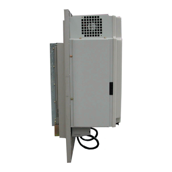
Seite 14: Abmessungen Und Gewichte
Abmessungen und Gewichte � � � � � � Schaltschrankausschnitt ���� ���� � aussen innen Gehäuse Gewicht 34,5 165,5 5,1 kg 9 kg 20 kg 251,5 297,5 91 kg 52 kg 48,5 235,5 62 kg 1020 153,5 209,5 167 kg Maße der Schaltschrankausschnitte Gehäuse 4x80... -
Seite 15: Übersicht Der Leistungsteilanschlüsse
Übersicht der Leistungsteilanschlüsse Eingangsspannung beachten, da 230V und 400V-Klasse (3-phasig) möglich Gehäusegröße E Gehäusegröße G � �� �� �� �� �� �� �� � � � T1 T2 Gehäusegröße H L1, L2, L3 3-phasiger Netzanschluss U, V, W Motoranschluss PE ++ PE U ++, PB Anschluss für Bremswiderstand... -
Seite 16: Anschluss Leistungsteil
Das Vertauschen von Netz- und Motoranschluss Auf Anschlussspannung und richtige führt zur sofortigen Zerstörung des Gerätes. Polung des Motors achten ! 3-ph. Anschluss DC-Versorgung 420...720V DC (400V-Klasse) Netzsicherungen KEB COMBIVERT Hauptschütz Motordrossel oder Ausgangsfilter (nicht bei F5-M oder F5-S) Netzdrossel Motor Funkentstörfilter Montageplatte... - Seite 17 � � Anschluß P-Gehäuse/ Verschaltung 2 � � � � � � � �� ������������ �� ��������������� �� � �� �� �� �� ������������ �� ����������� �� � Anschluß P-Gehäuse/ Verschaltung 3 COMBIVERT F5 mit Steuerkarte COMBIVERT F5 nur TL-Teil...
- Seite 18 Anschluß P-Gehäuse/ Verschaltung 4 COMBIVERT F5 mit Steuerkarte COMBIVERT F5 nur TL-Teil COMBIVERT F5 nur TL-Teil Zuleitung Hauptabsicherung Hauptschütz Netzdrossel mit Temperaturerfassung HF-Filter KEB COMBIVERT Klemmblock Motor Montageplatte Symmetrierdrosseln bei Parallelschaltung mehrerer Umrichter...
- Seite 19 Netzdrosseln in Reihe zu schalten, da diese sonst im Fehlerfall durch Überhitzung zerstört werden. Der Temperaturschalter für den Motor ist optional. 1 Zuleitung 2 Hauptabsicherung 3 Hauptschütz 4 Netzdrossel mit Temperaturerfassung 5 HF-Filter 6 Verbindungsleitung 7 KEB COMBIVERT 8 Motor 9 Montageplatte...
- Seite 20 Netzdrosseln in Reihe zu schalten, da diese sonst im Fehlerfall durch Überhitzung zerstört werden. Der Temperaturschalter für den Motor ist optional. 1 Zuleitung 2 Hauptabsicherung 3 Hauptschütz 4 Netzdrossel mit Temperaturerfassung 5 HF-Filter 6 Verbindungsleitung 7 KEB COMBIVERT 8 Motor 9 Montageplatte...
- Seite 21 Hinweis zum Anschluss 2 x 3 ph Der Überwachungsschalter der Hauptabsicherung muß an die Netz-Aus Kette angeschlossen oder die Reglerfreigabe weggeschaltet werden! Netz: 2 x 3 x 305 - 500 V 60° elektrisch verschben Die B12 Gleichrichterschaltung erwirkt eine Reduzierung der Netzrückwirkungen bei großen Leistungen.
-
Seite 22: Anschluss Bremswiderstand
Anschluss Bremswi- Um die Überhitzung eines Bremswiderstandes zu erfassen ist es unbedingt er- forderlich den Temperaturschalter des Bremswiderstandes zu überwachen. Die derstand Überhitzung kann folgende Ursachen haben: • Rampen zu kurz oder zu lange Einschaltdauer • Dimensionierung des Bremswiderstandes falsch •... -
Seite 23: Temperaturregelung
Temperaturregelung enthält, ist eine Inbetriebnahme nur unter Verwendung der Applikationsanleitung für F5-M ab Version 2.7 möglich. Die entsprechen- den Parameter sind in Kapitel 6.8 und 8.1 zu finden. Zum Erwerb dieser Anleitung wenden Sie sich bitte an KEB. Allgemeines Wassergekühlte Frequenzumrichter beinhalten die gesamten Erfahrungen mit den luftgekühlten Frequenzumrichtern. -
Seite 24: Temperatur, Betauung Und Transport
Die Zulauftemperatur darf maximal 40°C betragen. Bedingt durch hohe Luftfeuch- Temperatur, Betau- tigkeit und hohe Temperaturen kann es zur Betauung führen. Betauung stellt eine ung und Transport Gefahr für den Umrichter dar, da durch eventuell entstehende Kurzschlüsse der Umrichter zerstört werden kann. Der Anwender stellt sicher, dass jegliche Betauung vermieden wird! Um eine Betauung zu vermeiden, gibt es folgende Möglichkeiten. -
Seite 25: Parameterbeschreibung
Achtung! Nur mit KTY- oder PT100-Sensoren im Motor und entsprechender Hinweis zur Motortemperaturre- werksseitig eingebauter Auswertung möglich! gelung Diese Option steht ab Gehäusegrösse G zur Verfügung. Ein KTY- oder PT100- Sensor erfasst die Temperatur ausschließlich an einer Stelle. Sollte ein Wicklungs- vollschutz aller drei Phasen zusätzlich gefordert sein, dann lässt sich dieses in Absprache mit dem Hersteller der Motoren, z.B. - Seite 26 Möglichkeiten zur Temperaturre- Zur Temperaturregelung stehen zwei Wege zur Verfügung: gelung a.) mit Temperaturüberwachung im Motor b.) ohne Temperaturüberwachung im Motor a.) Temperaturregelung mit Bei dieser Temperaturregelung verfügen Umrichter und Motor über voneinander Temperaturüberwachung im unabhängige Kühlkreisläufe. Zur Ansteuerung der Ventile werden zwei program- Motor mierbare Ausgänge der Steuerkarte benötigt (siehe nachfolgende Abbildung).
-
Seite 27: Anschluss An Das Kühlsystem
Der Kühlwasseranschluss ist mit elastischen, druckfesten Schläuchen auzuführen Anschluss an das und mit Schellen zu sichern (Fließrichtung beachten und auf Dichtheit prüfen!) Für die Kühlsystem Anbindung an das Kühlsystem ist der standardmäßig mitgelieferte Anschlussstutzen mit 1/2-Zoll-Verschraubung 00.00.650-G012 zu verwenden (Whitworth-Rohrgewinde nach DIN ISO 228-1). -
Seite 28: Taupunkte U. Elektrochemische Spannungsreihe
offener Kühlkreislauf Beim offenenen Kühlkreislauf wird ständig neue Kühlflüssigkeit zugeführt und direkt abgeführt. Bei dieser Art der Wasserkühlung kann die Kühlflüssigkeit sehr leicht verunreinigt werden, daher ist der offene Kühlkreislauf nicht zu empfehlen. Ventil Zulauf do.xx COMBIVERT Ablauf Umrichterschutz- Die Umrichter-Abschalttemperaturen liegen bei 60° C und 90° C, je nach Leistungs- teilausführung und Überlastfähigkeit. -
Seite 29: Anhang
Anhang Überlastkennlinien Kennlinie 1 Kennlinie 2 Zeit [s] Zeit [s] Auslastung [%] Auslastung [%] 105 110 115 120 125 130 135 140 145 150 105 110 115 120 125 130 135 140 145 150 160 170 180 190 200 210 220 In diesem Bereich fällt die Kennlinie abhängig von der Überstromgrenze ab (siehe Geräteidentifikation). -
Seite 30: Sicherer Halt Gemäß En954-1/ Kat. 3
Relais. Die Arbeitsweise des Relais wird von der programmierten Elektronik zyklisch überwacht. Durch die Sicherheit wird zur Erfüllung der Norm beim KEB COMBIVERT keine weitere Maßnahme (z.B. Rückmeldung über Relaiskontakt) benötigt, da ein einzelner Fehler in der Steuerung nicht zum Verlust der Halt-Funktion führt. -
Seite 31: Absicherung, Klemmen, Querschnitt Und Anzugsmomente
Absicherung, Klemmen, Querschnitt und Anzugsmomente FU-Größe RK5 Fuse [A] Klemme [mm Querschnitt Anzugsmoment [Nm] 230V 480V metr. 09.F5.D 0,2-4 24-10 10.F5.D 0,2-4 24-10 12.F5-D 0,2-4 24-10 13.F5.D 0,2-4 24-10 14.F5.D 0,2-4 24-10 13.F5.E 0,5-10 20-6 14.F5.E 0,5-10 20-6 13.F5.E 0,2-4 24-10 14.F5.E 0,2-4... - Seite 64 • mail: info@keb.de KEB Italia S.r.l. KEB Antriebstechnik GmbH & Co. KG Via Newton, 2 • I-20019 Settimo Milanese (Milano) Wildbacher Str. 5 • D–08289 Schneeberg fon: +39 02 33500782 • fax: +39 02 33500790 fon: +49 3772 67-0 • fax: +49 3772 67-281 net: www.keb.it...