KEB Combivert F5 Installationsanleitung
Vorschau ausblenden
Andere Handbücher für Combivert F5:
- Betriebsanleitung (164 Seiten) ,
- Gebrauchsanleitung (104 Seiten) ,
- Bedienungsanleitung (84 Seiten)
Inhaltsverzeichnis
Verfügbare Sprachen
Verfügbare Sprachen
Allgemeine
EMV- und Sicher-
heitshinweise im
Downloadbereich
unter www.keb.de
beachten !
The general
EMC and safety
directions at
www.keb.de have
to be observed !
Mat.No.
00F501M-KE03
C O M B I V E R T
Installationsanleitung
Installation Manual
Rev.
1J
5,5...7,5 kW
4,0...15 kW
5.5...7.5 kW
4.0...15 kW
Gehäuse E
230 V
400 V
Housing E
230 V
400 V
D
GB
Kapitel
Inhaltsverzeichnis

Verwandte Anleitungen für KEB Combivert F5


Inhaltszusammenfassung für KEB Combivert F5
- Seite 1 C O M B I V E R T Allgemeine EMV- und Sicher- heitshinweise im Downloadbereich unter www.keb.de beachten ! The general EMC and safety directions at www.keb.de have to be observed ! Installationsanleitung Gehäuse E 5,5…7,5 kW 230 V 4,0…15 kW...
- Seite 3 D - 3...
- Seite 4 Diese Anleitung beschreibt den KEB COMBIVERT F5. Im Einzelnen wird auf den Einbau, die An- schlussmöglichkeiten sowie die grundlegende Bedienung eingegangen. Aufgrund der vielfältigen Einsatz- und Programmiermöglichkeiten ist der anwendungsspezifische Anschluss- bzw. Verdrah- tungsplan, die Parametereinstellung sowie Hinweise zur Inbetriebnahme der Dokumentation des Maschinenherstellers zu entnehmen.
-
Seite 5: Inhaltsverzeichnis
Inhaltsverzeichnis Sicherheits- und Parameterbeschreibungen ....25 Anwendungshinweise ......6 Basic/Compact/General/Application ohne Geberinterface......25 Produktbeschreibung ......7 Parameterbeschreibung für Multi und Verwendungszweck....... 7 Application mit Geberinterface .... 31 Geräteidentifikation ....... 7 Parameterbeschreibung für F5-Servo . 35 Technische Daten ........8 2.3.1 230 V-Klasse .......... 8 Anhang A ............ -
Seite 6: Wichtig, Unbedingt Lesen
Wichtig, unbedingt lesen Sicherheits- und Anwendungshinweise Sicherheits- und Anwendungshinweise für Antriebsstromrichter (gemäß: Niederspannungsrichtlinie 2006/95/EG) 1. Allgemein Antriebsstromrichter enthalten elektrostatisch gefährdete Bauelemente, die leicht durch unsachgemäße Behandlung be- Während des Betriebes können Antriebsstromrichter ihrer schädigt werden können. Elektrische Komponenten dürfen nicht Schutzart entsprechend spannungsführende, blanke, gegebe- mechanisch beschädigt oder zerstört werden (unter Umständen nenfalls auch bewegliche oder rotierende Teile, sowie heiße... -
Seite 7: Produktbeschreibung
Produktbeschreibung Produktbeschreibung Verwendungszweck Der Frequenzumrichter KEB COMBIVERT F5 dient ausschließlich zur Steuerung und Re- gelung von Drehstrommotoren. Der Betrieb anderer elektrischer Verbraucher ist untersagt und kann zur Zerstörung der Geräte führen. Frequenzumrichter sind Komponenten, die zum Einbau in elektrische Anlagen oder Ma- schinen bestimmt sind. -
Seite 8: Technische Daten
Produktbeschreibung Technische Daten 2.3.1 230 V-Klasse Gerätegröße Gehäusegröße Netzphasen Ausgangsbemessungsleistung [kVA] Max. Motorbemessungsleistung [kW] Ausgangsbemessungsstrom Ausgangsbemessungsstrom UL Max. Kurzzeitgrenzstrom 49,5 OC-Auslösestrom Eingangsbemessungsstrom Eingangsbemessungsstrom UL Max. zulässige Netzsicherung Typ gG Bemessungsschaltfrequenz [kHz] Max. Schaltfrequenz [kHz] Verlustleistung bei Bemessungsbetrieb Verlustleistung bei DC-Betrieb Minimaler Bremswiderstand [Ω] Maximaler Bremsstrom... -
Seite 9: Klasse
Produktbeschreibung 2.3.2 400 V-Klasse Gerätegröße Gehäusegröße Netzphasen Ausgangsbemessungsleistung [kVA] 6,6 Max. Motorbemessungsleistung [kW] Ausgangsbemessungsstrom [A] 9,5 16,5 Ausgangsbemessungsstrom UL [A] 7,6 Max. Kurzzeitgrenzstrom [A] 17 21,6 29,7 49,5 OC-Auslösestrom [A] 21 25,9 35,6 Eingangsbemessungsstrom [A] 13 Eingangsbemessungsstrom UL [A] 10,6 15,4 19,6 27,3 Max. -
Seite 10: Abmessungen Und Anschlüsse
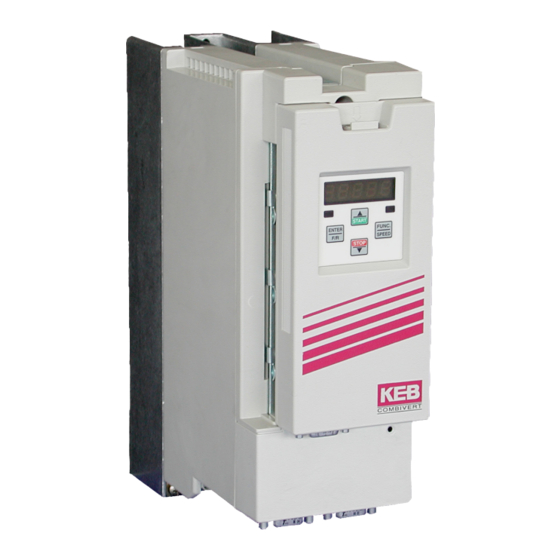
Produktbeschreibung Abmessungen und Anschlüsse * mit Operator Anschluss für Netzversorgung, Motor, Bremswiderstand und Temperaturerfassung Anschluss für Steuerleitungen Anschluss für Operator oder HSP5-Servicekabel Anschluss Abschirmung / Schutzleiter Eingangsspannung beachten, da 230 V und 400 V (3-phasig) möglich ! D - 10... -
Seite 11: Einbau Und Anschluss
• Alle Leitungen möglichst dicht an der Montageplatte verlegen - ideal im Metallkabelkanal. • COMBIVERT gut leitend mit der Montageplatte montieren. Lack vorher entfernen. Weitere Hinweise zur EMV - gerechten Verdrahtung finden Sie bei KEB im Internet. D - 11... -
Seite 12: Anschluss Des Leistungsteil
1,3 Nm (11,5 lb inches) 3.3.2 Verdrahtungshinweise Achten Sie unbedingt auf die Anschlussspannung des KEB COMBIVERT. Ein 230 V- Gerät am 400 V-Netz wird sofort zerstört. Vertauschen Sie niemals die Netz- und Motorleitung. In einigen Ländern wird gefordert, dass die PE-Klemme direkt im Klemmkasten (nicht über Montageplatte) angeschlossen wird. -
Seite 13: Netzanschluss
Einbau und Anschluss 3.3.3 Netzanschluss Netzanschluss 230 V 1-phasig Netzanschluss 230 V 3-phasig 1 x 180…260 Vac 3 x 180…260 Vac N/L2 N/L2 Absicherung Netzanschluss 400 V 3-phasig 3 x 305…528 Vac • Sicherung (siehe Kapitel 2.3) oder • Leistungsschutzschalter •... -
Seite 14: Motoranschluss
Einbau und Anschluss 3.3.4 Motoranschluss Maximale Motorleitungslänge siehe Kapitel 2.3 Abschirmungen großflächig auf N/L2 der Montageplatte und am Motor- gehäuse auflegen Motor-PTC (optional) 3.3.5 Anschluss der Temperaturerfassung • Klemmen T1, T2 • Ansprechwiderstand 1,65…4 kΩ • Rückstellwiderstand 0,75…1,65 kΩ • Ausführung gemäß VDE 0660 Teil 302 •... -
Seite 15: Anschluss Eines Bremswiderstandes Mit Brandschutz
Einbau und Anschluss 3.3.6 Anschluss eines Bremswiderstandes mit Brandschutz Bei einer Eingangsbemessungsspannung von 480 VAC darf bei Steuerungstyp „BASIC“ kein Bremswiderstand angeschlossen werden. Bei allen anderen Steuerungen muss die Ansprechschwelle des Bremstransistors (Pn.69) auf mindestens 770 Vdc eingestellt werden (siehe Anhang). Diese Schaltung bietet Schutz vor Überhitzung und Brand bei defektem Bremstransistor. -
Seite 16: Steuerkarte Basic
Einbau und Anschluss Steuerkarte BASIC 3.4.1 X2A Steuerklemmleiste • Anzugsmoment 0,22…0,25 Nm (2 lb inches) • abgeschirmte/verdrillte Leitungen verwenden 1 5 7 8 10 11 14 15 16 20 22 24 25 26 27 28 29 • Schirm einseitig am Umrichter auf Erdpotential legen PIN Funktion Name Erklärung... -
Seite 17: Anschluss Der Steuerklemmleiste
Einbau und Anschluss 3.4.2 Anschluss der Steuerklemmleiste Sollwertpotentiometer Stromsignal Sollwertsignal 3…10 kΩ 0…±20 mA 0…±10 V DC 4…20 mA Analogausgang ±10 V DC max. 5 mA nicht bei Gehäuse A und B max. 30 V DC / 0,01…1 A max. 30 V DC / 0,01…1 A Um Störungen zu vermeiden, ist für analoge und digitale Steuerleitungen ein getrennter Schirm vorzusehen. -
Seite 18: Steuerkarte Compact/General/Application Ohne Geberinterface
Einbau und Anschluss Steuerkarte Compact/General/Application ohne Geberinterface 3.5.1 X2A Steuerklemmleiste • Anzugsmoment 0,22…0,25 Nm (2 lb inches) • Abgeschirmte/verdrillte Leitungen verwenden • Schirm einseitig am Umrichter auf Erdpotential 1 2 3 4 5 6 7 8 9 10 11 12 13 14 15 16 17 18 19 20 21 22 23 24 25 26 27 28 29 legen PIN Funktion... -
Seite 19: Anschluss Der Steuerklemmleiste
Einbau und Anschluss 3.5.2 Anschluss der Steuerklemmleiste Sollwertpotentiometer Sollwertsignal Stromsignal 3…10 kΩ 0…±10 V DC 0…±20 mA 4…20 mA Analogausgang ±10 V DC / max. 5 mA *) Potenzialausgleichsleitung nur anschließen, wenn zwischen den Steuerungen ein Poten- zialunterschied >30 V besteht. Der Innenwi- derstand reduziert sich hierbei auf 30 kΩ. -
Seite 20: Steuerkarte Multi/Servo/Application Mit Geberinterface
Einbau und Anschluss Steuerkarte Multi/Servo/Application mit Geberinterface 3.6.1 X2A Steuerklemmleiste • Anzugsmoment 0,22…0,25 Nm (2 lb inches) • Abgeschirmte/verdrillte Leitungen verwenden • Schirm einseitig am Umrichter auf Erdpotential 1 2 3 4 5 6 7 8 9 10 11 12 13 14 15 16 17 18 19 20 21 22 23 24 25 26 27 28 29 legen PIN Funktion... -
Seite 21: Anschluss Der Steuerklemmleiste
Einbau und Anschluss 3.6.2 Anschluss der Steuerklemmleiste Sollwertpotentiometer Sollwertsignal 3…10 kΩ 0…±10 V DC Analogausgang ±10 V DC / max. 5 mA *) Potenzialausgleichsleitung nur anschließen, wenn zwischen den Steuerungen ein Poten- zialunterschied >30 V besteht. Der Innenwi- derstand reduziert sich hierbei auf 30 kΩ. max. -
Seite 22: Bedienung Des Gerätes
4.1.2 Digitaloperator (Artikelnummer 00F5060-1100) Als Zubehör zur lokalen Bedienung des KEB COMBIVERT F5 ist ein Operator erhältlich. Um Fehlfunktionen zu vermeiden, muss der Umrichter vor dem Aufstecken / Abziehen des Operators in den Status noP (Reglerfreigabe öffnen) gebracht werden. Bei der In- betriebnahme des Umrichters wird immer mit den zuletzt abgespeicherten Werten bzw. -
Seite 23: Fernbedienung
Operatoren für spezielle Einsatzfälle (Profibus, Interbus, Sercos, CAN) bestückt werden. Weitere Informationen hierzu finden Sie auf unserer Homepage. Tastaturbedienung 4.2.1 Parameternummern und /-werte Beim Einschalten des KEB COMBIVERT F5 erscheint der Wert des Parameters CP.1. Mit der Funktionstaste wird zwischen FUNC. Parameterwert und Parameternummer SPEED gewechselt. -
Seite 24: Rücksetzen Von Fehlermeldungen
Fehler selbst zurückzusetzen, muss erst die Ursache behoben werden und ein Reset oder ein Kaltstart erfolgen. 4.2.3 Passworteingabe Der KEB COMBIVERT ist mit einem umfassenden Passwortschutz ausgestattet. Abhängig vom eingegebenen Passwort sind folgende Modis möglich: Anzeige Modus CP_ro Endkundenmenü (CP-Parameter) nur lesen CP_on Endkundenmenü... -
Seite 25: Parameterbeschreibungen
CP-Parameter Parameterbeschreibungen Basic/Compact/General/Application ohne Geberinterface Auflö- Parameter Einstellbereich Default Einheit ↵ sung sprung CP.0 Passworteingabe 0…9999 ud.1 CP.1 Istfrequenzanzeige -400…400 0,0125 ru.3 CP.2 Sollfrequenzanzeige -400…400 0,0125 ru.1 CP.3 Umrichter Status 0…255 ru.0 CP.4 Scheinstrom 0…6553,5 ru.15 CP.5 Scheinstrom / Spitzenwert 0…6553,5 ru.16 CP.6... - Seite 26 CP-Parameter CP.3 Umrichterstatus Der Umrichterstatus zeigt den aktuellen Betriebszustand des Umrichters (z.B. Vorwärts- konstantlauf, Stillstand usw.) an. Im Fehlerfall wird die aktuelle Fehlermeldung angezeigt, auch wenn die Anzeige durch ENTER bereits zurückgesetzt wurde (Fehler-LED im Operator blinkt noch). „no Operation“; Reglerfreigabe nicht gebrückt; Modulation abgeschaltet; Aus- gangsspannung = 0 V;...
-
Seite 27: Cp.28 Reaktion Auf Externe Übertemperatur
CP-Parameter CP.24 Max. Rampenstrom Diese Funktion schützt den Frequenzumrichter vor dem Abschalten durch Überstrom während der Beschleunigung. Die Rampe wird bei Erreichen des hier eingestellten Wer- tes solange angehalten, bis der Strom wieder absinkt. Bei aktiver Funktion wird „LAS“ im Display (CP.3) angezeigt. -
Seite 28: Cp.29 Analogausgang 1 / Funktion
CP-Parameter CP.28 Anzeige Reaktion Wiederanlauf E.dOH sofortiges Abschalten der Modulation A.dOH Schnellhalt / Absch. der Modul. nach Erreichen von Fehler behe- ben; Reset Drehzahl 0 A.dOH Schnellhalt / Haltemoment bei Drehzahl 0 A.dOH sofortiges Abschalten der Modulation Autoreset, A.dOH Schnellhalt / Absch. der Modul. nach Erreichen von wenn kein Drehzahl 0 Fehler mehr... - Seite 29 CP-Parameter Störmelderelais (ohne Auto-Reset) Warn- oder Fehlermeldung bei Abnormal Stopping Überlast-Vorwarnung Übertemperatur-Vorwarnung Endstufen Externe Übertemperatur-Vorwarnung Motor Übertemperatur-Vorwarnung Umrichterinnenraum OHI Kabelbruch 4...20 mA an Analogeingang 1 max. Konstantstrom (Stall, CP.25) überschritten max. Rampenstrom (LA-Stop, CP.24) überschritten DC-Bremsung aktiv Istwert=Sollwert (CP.3=Fcon; rcon; nicht bei noP, LS, Fehler, SSF) Beschleunigen (CP.3 = FAcc, rAcc, LAS) Verzögern (CP.3 = FdEc, rdEc, LdS) Istdrehrichtung = Solldrehrichtung...
- Seite 30 CP-Parameter CP.34 Drehrichtungsquelle Mit diesem Parameter wird die Quelle und die Art der Auswertung für die Drehrichtungs- vorgabe festgelegt (Enter-Parameter). Mit CP.34 ändert man nicht die Drehrichtungsquelle der Festfrequenzen (CP.19…21). Wert Drehrichtung nur Applikationsmode Vorgabe über Klemmleiste vorwärts/rückwärts; negative Sollwerte werden zu Null gesetzt (Werkseinstellung) Vorgabe über Klemmleiste vorwärts/rückwärts;...
-
Seite 31: Parameterbeschreibung Für Multi Und Application Mit Geberinterface
Konstantlauf, Stillstand usw.) an. Im Fehlerfall wird die aktuelle Fehlermeldung angezeigt, auch wenn die Anzeige durch ENTER bereits zurückgesetzt wurde (Fehler-LED im Operator blinkt noch). Statusmeldungen und Informationen über die Ursache und Beseitigung, finden Sie unter "www.keb.de". D - 31... -
Seite 32: Cp.10 Konfiguration Drehzahlregelung
CP-Parameter CP.10 Konfiguration Drehzahlregelung Dieser Parameter aktiviert die Drehzahl-, bzw. die Drehmomentregelung. CP.10 Beschreibung Drehzahlregelung Drehmomentregelung Drehzahl-/Drehmomentregelung CP.17 Motoranpassung Werksmäßig ist der COMBIVERT je nach Gerätegröße auf einen speziellen Motor angepasst. Werden die Motordaten CP.11…CP.16 verändert, muss einmal CP.17 aktiviert werden. Damit werden die Stromregler, die Momentengrenzkennlinie und die Momentenbegrenzung neu eingestellt. - Seite 33 CP-Parameter CP.33 Relaisausgang 1 / Funktion CP.34 Relaisausgang 2 / Funktion CP.33/34 bestimmen die Funktion der beiden Relaisausgänge (X2A.24-26, X2A.27-29). Wert Funktion Keine Funktion (generell aus) Generell an Run-Signal; auch bei DC-Bremse Betriebsbereit-Signal (kein Fehler) Störmelderelais Störmelderelais (ohne Auto-Reset) Warn- o. Fehlermeldung nach Schnellhalt Überlast-Vorwarnung Übertemperatur-Vorwarnung Endstufen Ex.
-
Seite 34: Cp.35 Reaktion Auf Endschalterfehler
CP-Parameter CP.35 Reaktion auf Endschalterfehler Dieser Parameter bestimmt die Reaktion des Antriebes auf die Klemmen X2A.14 (F) bzw. X2A.15 (R), welche als Endschalter programmiert sind. Die Reaktion des Antriebes erfolgt entsprechend folgender Tabelle. CP.35 Anzeige Reaktion Wiederanlauf E.PRx sofortiges Abschalten der Modulation Schnellhalt / Abschalten der Modulation nach Fehler beheben, A.PRx... -
Seite 35: Parameterbeschreibung Für F5-Servo
Anzeige durch ENTER bereits zurückgesetzt wurde (Fehler- LED im Operator blinkt noch). Statusmeldungen und Informationen über die Ursache und Beseitigung, finden Sie unter „www.keb.de => Dokumentation => Bedienungsanleitungen => Sonstiges => Serviceinformationen => Fehler- und Statusmeldungen.doc“. - Seite 36 Werden Motoren mit ausgerichtetem Gebersystem verwendet, kann der durch das automatiche Abgleichen ermittelte Wert auch direkt unter CP.20 eingegeben werden. Die Abgleichwerte von bekannten Motoren der KEB COMBIVERT S4-Reihe, müssen mit der Polpaarzahl des Motors multipliziert werden. Die unteren 16 Bit des Ergebnisses müssen in CP.20 eingetragen werden.
- Seite 37 CP-Parameter CP.21 Drehrichtungstausch Geber 1 Die Drehzahlanzeige unter CP.1 muss bei Rechtsdrehung des Motors von Hand positiv sein. Wenn das Vorzeichen nicht stimmt, müssen bei Geräten mit Resolver SIN+ und SIN- vertauscht werden. Dabei ist darauf zu achten, dass die Signale nicht mit dem inneren Schirm kurzgeschlossen werden.
- Seite 38 CP-Parameter Wert Funktion Scheinstrom (CP.4) > Schaltpegel Rechtslauf (nicht bei nOP, LS, Schnellhalt oder Fehler) Linkslauf (nicht bei nOP, LS, Schnellhalt oder Fehler) Warnung E.OL2 Stromregler in der Begrenzung Drehzahlregler in der Begrenzung Betrag ANOUT1 > Schaltpegel Betrag ANOUT2 > Schaltpegel ANOUT1 >...
-
Seite 39: Überlastkennlinie
Anhang A Anhang A Überlastkennlinie Auslösezeit [s] Auslastung [%] Bei Überschreiten einer Auslastung von 105% startet ein Überlastintegrator. Bei Unter- schreiten wird rückwärts gezählt. Erreicht der Integrator die Überlastkennlinie, wird der Fehler E.OL ausgelöst. Berechnung der Motorspannung Die Motorspannung, für die Auslegung eines Antriebes, ist abhängig von den eingesetzen Komponenten. -
Seite 40: Lagerung
Wird der Kondensator nun mit Nennspannung in Betrieb genommen, wird versucht die Oxidschicht schlagartig wieder aufzubauen. Dies erzeugt Wärme sowie Gas und zerstört den Kondensator. Um Defekten vorzubeugen, muss der KEB COMBIVERT abhängig von der Lagerungsdauer gemäß folgender Aufstellung in Betrieb genommen werden: Lagerungszeitraum < 1 Jahr •... -
Seite 41: Ändern Der Ansprechschwelle Des Bremstransistors
Lagerungszeitraum > 3 Jahre • Eingangsspannungen wie zuvor, jedoch Zeiten pro Jahr verdoppeln. Eventuell Kondensatoren tauschen. Nach Ablauf dieser Inbetriebnahme kann der KEB COMBIVERT unter Nennbedingungen betrieben oder einer neuen Lagerung zugeführt werden. Ändern der Ansprechschwelle des Bremstransistors (nicht gültig für Steuerungstyp „BASIC“) Um ein vorzeitiges Durchschalten des Bremstransistors bei einer Eingangsbemessungs- spannung von 480 Vac zu vermeiden, muss die Ansprechschwelle gemäß... - Seite 92 +39 02 3353531 • fax: +39 02 33500790 net: www.keb.de • mail: kebitalia@keb.it KEB Power Transmission Technology (Shanghai) Co.,Ltd. KEB Japan Ltd. No. 435 Qianpu Road, Chedun Town, Songjiang District, CHN-Shanghai 201611, P.R. China 15–16, 2–Chome, Takanawa Minato-ku fon: +86 21 37746688 • fax: +86 21 37746600...