Herunterladen Inhalt Inhalt Diese Seite drucken
tau K126MA Installationsanleitung
Vorschau ausblenden Andere Handbücher für K126MA:

Werbung

Verfügbare Sprachen
  • DE

Verfügbare Sprachen

  • DEUTSCH, seite 28
GUIDA ALL'INSTALLAZIONE
INSTALLATION GUIDE
INSTALLATIONSANLEITUNG
NOTICE D'INSTALLATION
GUÍA PARA LA INSTALACIÓN
GUIA DE INSTALAÇÃO
K126MA
IT - Istruzioni originali

Werbung

Inhaltsverzeichnis
loading

Inhaltszusammenfassung für tau K126MA

  • Seite 1 GUIDA ALL’INSTALLAZIONE INSTALLATION GUIDE INSTALLATIONSANLEITUNG NOTICE D’INSTALLATION GUÍA PARA LA INSTALACIÓN GUIA DE INSTALAÇÃO K126MA IT - Istruzioni originali...
  • Seite 2 SCHEMA K126MA SCHALTPLAN SCHÉMA ESQUEMA DEL ESQUEMA CABLAGGIO WIRING DER K126MA CÂBLAGE CABLEADO DE LIGAÇÕES K126MA DIAGRAM K126MA K126MA K126MA Dip-switches 9 10 11 12 LIMIT SWITCH Trimmer: RALL 9 10 11 12 RALL K126MA PROG LEDs: FIXED SAFETY EDGE EXT.
  • Seite 3: Power Supply

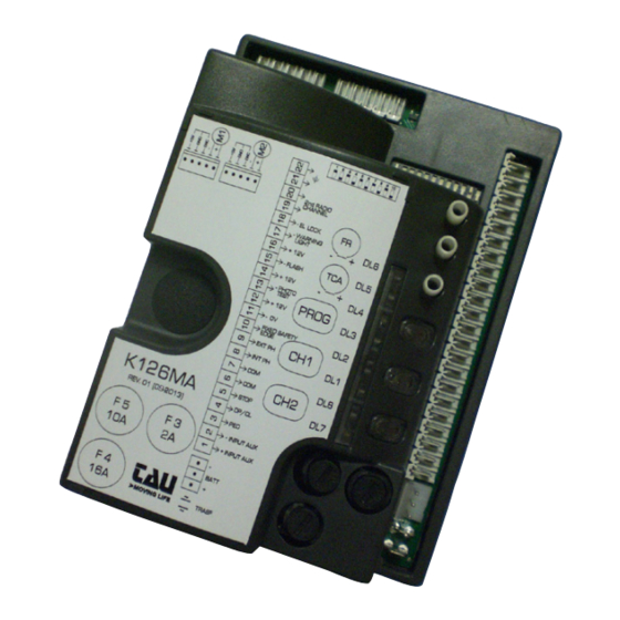
    - Morsetti 1 - 2: Attenzione a NON invertire la polarità. - Se il jumper J6 non è inserito, verrà attivata la modalità basso consumo e, al ter- mine di ogni manovra, le uscite 11-12, 12-13, 14-15, 16-17 e 16-18 verranno spente. - Terminals 1 –...
  • Seite 4: Avvertenze Importanti

    Avvertenze importanti: Togliere l’alimentazione di rete alla scheda prima di accedervi. La centralina K126MA è destinata al comando di un motoriduttore elettromeccanico in corrente continua per l’automazione di cancelli, porte e portoni. Ogni altro uso è improprio e, quindi, vietato dalle normative vigenti.
  • Seite 5: Caratteristiche Tecniche

    PEDONALE, ecc), al fine di evitare malfunzionamenti del cancello si renderà necessario disac- coppiare i vari comandi mediante RELAYS oppure utilizzando il nostro dispositivo 750T-RELE. 2. INTRODUZIONE La scheda K126MA può funzionare in due modalità differenti, selezionabili tramite il ponticello J6 (vedi schema cablaggio). J6 Ponticellato: modalità...
  • Seite 6 (vedi nota alla fine del paragrafo). ATTENZIONE: l’uscita di default è monostabile attiva 2 sec. Per com- mutarla in bistabile attiva oppure per modificare il tempo di attiva- zione è necessario operare tramite programmatore palmare TAU- PROG (vedi istruzioni relative).
  • Seite 7: Regolazioni Logiche

    ingresso antenna radioricevente ad innesto solo per ricevitori 433,92 21 - 22 ANTENNA MHz. (21= MASSA - 22= SEGNALE) uscita alimentazione motore (M2) 18V DC max 300 VA. MOTORE 23 - 24 (M2) (23= POSITIVO - 24= NEGATIVO) Vedi nota sotto. FINECORSA 25 - 27 Ingresso finecorsa opzionali: 25 cavo grigio;...
  • Seite 8 in seguito all’intervento del contatto fotocellula (ingresso 7 - 9), l’automazione RICHIUDE si chiude automaticamente dopo 5 secondi. DOPO FOTOCELLULA Off funzione disinserita. On l’automazione ignora i comandi di chiusura durante l’apertura e il tempo di pausa. NO REVERSE Off l’automazione si comporta come stabilito dal dip switch nr. 2. On la funzione prelampeggio è...
  • Seite 9 - I fermi meccanici dell’automazione devono necessariamente essere installati e regolati sia in apertura che in chiusura (vedi istruzioni motore). - La posizione dei dip 9, 10 e 11. Devono essere settati in base al modello di automazione utilizzata (vedi tabella dip 9-10-11, sez. “Regolazioni logiche”). IMPORTANTE: Eseguire la prima memorizzazione corsa con il trimmer RAL posizionato completamente girato in senso antiorario (velocità...
  • Seite 10 (il sistema non interviene attuando movimenti di sicurezza, ma solo fermando l’automazione). 7. CARATTERISTICHE DELLA K126MA APERTURA E CHIUSURA COMANDATA DA OROLOGIO É possibile comandare l’apertura e la chiusura dell’automazione mediante un orologio digitale che in uscita disponga di un contatto pulito N.A.
  • Seite 11 LED - DL7 Il led DL7, oltre ad indicare la presenza della batteria, segnala eventuali errori con una serie di lampeggi predefiniti di diversi colori: Legenda: led acceso fisso; led lampeggiante; batteria carica, tensione di rete presente; sempre acceso (Verde): batteria in carica;...
  • Seite 12 errore comunicazione master/slave; 6 lampeggi (Giallo): Verificare il cablaggio tra le centrali, verificare l’efficienza della centrale slave (fusibili), verificare l’efficienza delle schede di interfaccia; Intervento sicurezza bordo sensibile 7 lampeggi (Rosso): È necessario un impulso di comando per effettuare la chiusura; errore memoria Eeprom esterna;...
  • Seite 13 L’indicazione dello sforzo è codificato secondo lo schema della seguente tabella: Livello (Spento) (Spento) (Verde) (Spento) (Verde) (Verde) (Verde) (Giallo) (Giallo) (Verde) (Giallo) (Giallo) (Giallo) (Rosso) (Rosso) (Giallo) (Rosso) (Rosso) Dopo 5 minuti di inattività la scheda ritornerà alla visualizzazione classica (per tornare manualmente alla visualizzazione classica ripremere contemporaneamente i tre tasti).
  • Seite 14 8_ se si desidera uscire dalla modalità di apprendimento senza memorizzare un codice, premere breve- mente il tasto CH1 o il tasto CH2. Nel caso di raggiungimento del nr massimo di radiocomandi (nr 30), il led DL8 lampeggia velocemente per circa 3 secondi senza però eseguire la memorizzazione. PROGRAMMAZIONE REMOTA TRAMITE T-4RP e K-SLIM-RP / S-2RP / S-4RP (V 4.X) Con la versione di software V 4.X è...
  • Seite 15 14. GARANZIA: CONDIZIONI GENERALI La garanzia della TAU ha durata di 24 mesi dalla data di acquisto dei prodotti (fa fede il documento fiscale di vendita, scontrino o fattura). La garanzia comprende la riparazione con sostituzione gratuita (franco sede TAU: spese di imballo e di trasporto sono a carico del cliente) delle parti che presentano difetti di lavorazione o vizi di materiale riconosciuti dalla TAU.
  • Seite 16: Important Warnings

    WARNINGS This manual is designed to assist qualified installation personnel only. It contains no information that may be of interest to final users. This manual is enclosed with control unit K126MA and may therefore not be used for different products! Important warnings: Disconnect the mains power supply to the board before accessing it.
  • Seite 17: Technical Characteristics

    STRIAN, etc.), in order to avoid gate malfunctions, it will be necessary to uncouple the various controls using RELAYS or using our 750T-RELE device. 2. INTRODUCTION The K126MA board has two working modes, selectable through the J6 jumper (see wiring diagram). J6 Jumped: standard mode, i.e. the control unit is powered all the time;...
  • Seite 18 OPEN/CLOSE button N.O. input – Controls the opening and closing of the 4 - 6 OPEN/CLOSE automation and is regulated based on the function of dip-switches 2 and 4. (4= O/C - 6= COM) STOP button N.C. input – Stops the automation in any position, temporarily pre- venting the automatic closure, if programmed.
  • Seite 19 motor (M2) supply output 18V DC max. 300 VA. 23 - 24 MOTOR (M2) (23= POSITIVE - 24= NEGATIVE) See note below. OPTIONAL LIMIT 25 - 27 Optional limit switches input: 25 - gray cable; 27 - red cable. SWITCHES Not in use motor (M1) supply output 18V DC max.
  • Seite 20 after the photocell is activated (input 7 - 9), the automation closes au- CLOSES AGAIN tomatically after 5 seconds. AFTER THE PHOTOCELL function off. the automation ignores the closure command during opening and auto-close time NO REVERSE the automation responds as established by dip switch No. 2. the pre-flashing function is enabled.
  • Seite 21 - the position of dip-switches 9, 10 and 11. Dip-switches must be set according to the automation model (see table of dip-switches 9-10-11, “Logic adjustments” section). IMPORTANT: Carry out the first stroke memorization with the RAL trimmer positioned fully turned counterclockwise (minimum deceleration speed). -If the gate fails to move forward during the stroke memorization procedure, it is possible to increase the speed using the CH1 (= - minus) and CH2 (= + increase) keys.
  • Seite 22: Diagnostics Led

    Please remember that an obstacle during saving is interpreted as a mechanical limit stop (the system does not start any safety operation, it just stops the motor) 7. K126MA CHARACTERISTICS TIMER-OPERATED OPENING AND CLOSING CYCLES The opening/closing of the automation can be controlled by means of a timer that has a free N.O.
  • Seite 23 Key: led always on; led flashing; fully-charged battery, main voltage present; always on (green): battery charging; always on (yellow): fully-charged battery, no main voltage; 1 flash every 4 seconds (green): Check the main voltage; power supply through photovoltaic panel (terminals 1-2), 1 flash every 4 seconds (yellow): battery charger disabled low battery;...
  • Seite 24 Eeprom external memory fault; 8 (red) flashes: Replace the external memory module; Eeprom data error (internal/external); 8 (yellow) flashes: Perform procedure RADIO MEMORY RESET; Apart from the logic mistakes, the DL8 LED indicates also the status of the control unit during the sav- ing of the radio controls.
  • Seite 25: Mhz Built-In Radio Receiver

    The absorption registered is shown according to the following diagram: Level (Off) (Off) (Green) (Off) (Green) (Green) (Green) (Yellow) (Yellow) (Green) (Yellow) (Yellow) (Yellow) (Red) (Red) (Yellow) (Red) (Red) After 5 minutes from the function activation, the board automatically resumes to the standard LED visualization (to resume manually press simultaneously CH1, PROG and CH2).
  • Seite 26: Memory Capacity

    12. SET-UP FOR OPERATION WITH TAU APPS In order to use the TauApp and TauOpen apps, it will be necessary to connect to input J4 of the K126MA control unit using the supplied cable, the respective T-WIFI and T-CONNECT devices. To activate the...
  • Seite 27 14. GUARANTEE: GENERAL CONDITIONS TAU guarantees this product for a period of 24 months from the date of purchase (as proved by the sales document, receipt or invoice). This guarantee covers the repair or replacement at TAU’s expense (ex-works TAU: packing and trans- port at the customer’s expense) of parts that TAU recognises as being faulty as regards workmanship...
  • Seite 28: Wichtige Hinweise

    Das vorliegende Handbuch ist nur für technisches, zur Installation qualifiziertes Personal bestimmt. Die im vorliegenden Heft enthaltenen Informationen sind für den Endbenutzer nicht interessant. Die- se Anleitung liegt der Steuerung K126MA bei und darf daher nicht für andere Produkte verwendet werden! Wichtige Hinweise: Vor Eingriffen an der Steuerkarte die Netzstromversorgung abtrennen.
  • Seite 29: Einführung

    Steuerungen über die RELAIS zu trennen oder unsere Vorrichtung 750T RELE zu nutzen. 2. EINFÜHRUNG Die Karte K126MA kann mit zwei verschiedenen Betriebsweisen arbeiten, wählbar mit dem Jumper 6 (siehe Verkabelungsplan). J6 Gebrückt: Modalität Standard, das heißt, das Steuergerät ist immer gespeist;...
  • Seite 30 Eingang externe Stromversorgung (z. B. Fotovoltaiksystem 12V DC). Hinweis: Ab den neuen Versionen ist eine Spannungsänderung mit dem Jumper J7 nicht mehr erforderlich (prüfen Sie, ob diese auf der PHOTOVOLTAIC SYSTEM 1 - 2 Karte vorhanden ist). INPUT ACHTUNG: BEI SPEISUNG DES STEUERGERÄTES ÜBER EINE EXTERNE QUELLE NEHMEN ALLE ANDEREN AUSGÄNGE  ...
  • Seite 31: Einstellung Der Logik

    DC Ausgang für die Versorgung der Blinkleuchte max. 20W. Das Blinken wird von der Steuerung bestimmt; Langsamblinken in Öff- 14 - 15 ** BLINKLEUCHTE nung und Schnellblinken in Schließung. (14= PLUS - 15= MINUS) Ausgang für KONTROLLLEUCHTE TOR OFFEN max. 18V DC.
  • Seite 32 damit die neuen Einstellungen aktiviert werden. TRIMMER RALL Geschwindigkeitsanpassung während der Verlangsamung des Hubs in op/cl; ANMERKUNG: Beim Speichern des Hubs TRIMMER RALL wird empfohlen, ihn vollständig gegen den Uhrzeigersinn einzustellen (minimale Ver- langsamungsgeschwindigkeit). Einstellung des Ansprechvermögens bei der Wahrnehmung von Hindernissen. Anmerkung: durch Drehung des TRIMMERS FR.
  • Seite 33: Vorgehenswei Se Ohne Angeschlossen Optionale Endschalter

    9-10-11 Automatisierungstyp Selektion Dip 9 Dip 10 Dip 11 Automatisierungstyp T-ONE10B geeignet für Schiebetore bis 600 kg T-ONE10B für Schiebetore von 600 bis 1000 kg T-ONE8BR (24v) MASTER-R (24V Öffnungsgeschwindigkeit = Schließgeschwindigkeit) MASTER18QR MASTER-R (24V) T-ONE8BR (24V Öffnungsgeschwindigkeit = Schließgeschwindigkeit) CANTILEVER TONE10B (schwer) WICHTIG: Falls die Automatisierungstyp sich ändern sollte, dann muß...
  • Seite 34: Verfahren Zum Speichern Des Torhubes Mit Optionalen Endschaltern

    Anschlag interpretiert (das System greift aus Sicherheitsgründen nicht ein, aber die Automatisierung bleiben stehen). 7. MERKMALE DER SCHALT- UND STEUERTAFEL K126MA ÖFFNUNG UND SCHLIEßUNG MIT ZEITUHR Die Öffnung und Schließung der Automatisierung kann über eine digitale Uhr gesteuert werden, die im Ausgang über einen potentialfreien NO-Kontakt (Relais) verfügt.
  • Seite 35: Batterieladekarte (Eingebaut)

    BATTERIELADEKARTE (EINGEBAUT) Wenn man die Batterie anschließt, funktioniert die Automatisierung auch bei Netzstromausfall. Wenn die Spannung unter 11,3 Vdc sinkt, wird die Automatisierung nicht mehr funktionieren (die Steuertafel bleibt jedoch gespeist); wenn die Spannung dagegen unter 10,2 Vdc sinkt, schaltet die Karte die Batterie ganz ab (die Steuertafel ist nicht mehr gespeist).
  • Seite 36 Aufblinken abwechselnd Abspeicherung muss vorgenommen werden; (rot/grün) schnelles abwechselndes Speicherung der durchzuführenden Verlangsamungsvariation; Blinken : (grün/gelb) Die Platine erkennt die Positionsänderung des RALL-Trimmers und signa- lisiert die durchzuführende Speicherung zum Einlernen der neuen Ver- langsamung. Drücken Sie die PROG-Taste (siehe Absatz “RALL-Trimmer”) Abspeicherung läuft;...
  • Seite 37: Funktion Anzeige Der Motorbeanspruchung

    Kanal CH1 wartet auf Löschung; Aufblinken (grün): Kanal CH1 wird gelöscht; Immer an (grün): Kanal CH2 wartet auf Löschung; Aufblinken (gelb): Kanal CH2 wird gelöscht; Immer an (gelb): Kanal CH3 wartet auf Löschung; Aufblinken (rot): Kanal CH3 wird gelöscht; Immer an (rot): Das gleichzeitige Aufblinken der LEDs DL7 und DL8 zeigt an: Verfahren Reset Werkseinstellungen wartet auf Bestätigung;...
  • Seite 38: Eingebauter 433,92 Mhz Funkempfänger

    • Bei der Wiederherstellung nach einem Stromausfall (die Karte bleibt für eine gewisse Zeit ohne Stromversorgung) oder nach einem Eingriff von Hand (ohne Unterbrechung der Stromversorgung der Karte für eine Zeit von mehr als 5 Sekunden) wechselt die Automatisierung bei der Suche des Anschlags Öffnung zur verlangsamten Phase (Manöver VERLANGSAMUNG).
  • Seite 39: Vorbereitung Für Den Betrieb Mit Tau-Applikationen

    12. VORBEREITUNG FÜR DEN BETRIEB MIT TAU-APPLIKATIONEN Um die Applikationen TauApp und TauOpen verwenden zu können, müssen die entsprechenden T- WIFI- und T-CONNECT-Geräte mit dem mitgelieferten Kabel an den Eingang J4 der K126MA-Steuerung angeschlossen werden. Informationen zum Aktivieren des Betriebs der Applikationen finden Sie in den entsprechenden An- weisungen.
  • Seite 40 Klemmen 23 - 24 (falls verwendet). 14. GARANTIE: ALLGEMEINE BEDINGUGEN Die Garantie der Firma TAU hat 24 Monate Gültigkeit ab Kaufdatum (das Datum muss durch eine Quit- tung oder Rechnung belegt sein). Die Garantie schließt die Reparatur mit kostenlosem Ersatz (ab Werk der Firma TAU: Verpackungs- und Transportkosten gehen zu Lasten des Kunden) jener Teile ein, die von TAU anerkannte Fabrikations- oder Materialfehler aufweisen.
  • Seite 41 Le présent manuel est destiné exclusivement au personnel technique qualifié pour l’installation. Aucune in- formation contenue dans ce fascicule ne peut être considérée comme intéressante pour l’utilisateur final. Ce manuel est joint à la logique de commande K126MA, il ne doit donc pas être utilisé pour des produits différents ! Recommandations importantes : Couper l’alimentation électrique de la carte avant d’y accéder.
  • Seite 42: Caractéristiques Techniques

    OUVRE/FERME, STOP, PIETON etc.) et pour éviter un mauvais fonctionnement du portail, nous conseillons d’utiliser un relais pour découpler les commandes (modèle relais TAU 750T-RELE). 2. INTRODUCTION La fiche K126MA peut fonctionner en deux modalités différents, sélectionnables par pontet J6 (voir schéma de câblage). J6 pontés: modalité...
  • Seite 43 Entrée d’alimentation externe (ex. Système photovoltaïque 12V DC). NB: Dans les nouvelles versions des centrales de commande, le chan- gement de tension par le jumper J7 n’est plus nécessaire (vérifiez PHOTOVOLTAIC s’il est présent dans la centrale) 1 - 2 ATTENTION : EN ALIMENTANT LA CENTRALE AVEC UNE SOURCE SYSTEM INPUT EXTERIEURE, TOUTES LES AUTRES SORTIES 18V (24V pour MASTER-R)
  • Seite 44 Sortie éclairage automatique auxiliaire 18V DC max 15 W. Elle s’allume commandée par impulsion et reste allumée au-delà du 16 - 18* ** ÉCLAIRAGE temps de la manœuvre pour une durée réglable avec TAUPROG (par défaut 2 secondes) (16= POSITIF - 18= NEGATIVE) sortie 2 canal radio - pour commander un autre automatisme ou allumer des lumières, etc.
  • Seite 45 TRIMMERS RALL réglage de la vitesse pendant le ralentissement de la course d'ouverture/fermeture ;. Remarque : lors de la mémorisation de la course, réglez le TRIMMER RALL com- plètement tourné dans le sens inverse des aiguilles d'une montre (vitesse de décélération minimale). réglage sensibilité...
  • Seite 46 “RÉGLAGES DE FABRIQUE“ (voir page 47). BORD SENSIBLE RESISTIF (étau n ° 10). BORD BARRE PALPEUSE CONTACT N.C. ( étau n ° 10). SENSIBLE Remarque: s’il n’est pas utilisé, maintenir le dip sur OFF. 6. PROCÉDURE DE MÉMORISATION DE LA COURSE DU PORTAIL ATTENTION : Après avoir alimenté...
  • Seite 47 (le système n’intervient pas avec des mouvements de sécurité, mais seulement avec l’arrêt du automatisation). CARACTÉRISTIQUES DE LA K126MA OUVERTURE ET FERMETURE COMMANDÉE PAR UNE HORLOGE Il est possible de commander l’ouverture et la fermeture de l’automatisme avec une horloge numé- rique disposant en sortie d’un contact N.O.
  • Seite 48: Détection Des Obstacles

    qu’à l’heure d’ouverture désirée, le contact relais de l’horloge se ferme jusqu’à l’heure de fermeture voulue (moment où le contact relais de l’horloge s’ouvre de nouveau en permettant ainsi la refermeture automatique). Note : la refermeture automatique doit être activée (dip-switch n. 1 sur ON). CARTE CHARGEUR DE BATTERIE (INTÉGRÉE) Si la batterie est connectée, en cas de coupure de courant l’automatisme fonctionne quand même.
  • Seite 49 LED - DL8 Le led DL8 signale des avertissements/erreurs de la logique de la fiche avec une série prédéfinie de clignotements de différents couleurs: Légende: led toujours allumé; led clignotement; 1 clignotement toutes les 4 secondes: fonctionnement normal; (vert) clignotant alternativement: mémorisation doit être exécuté;...
  • Seite 50 chaine CH1 en attente de programmation; toujours allumé (vert): mémoire chaine CH1 plaine; clignotement rapide (vert): chaine CH2 en attente de programmation; toujours allumé (jaune): mémoire chaine CH2 plaine; clignotement rapide (jaune): chaine CH3 en attente de programmation; toujours allumé (rouge): mémoire chaine CH3 plaine;...
  • Seite 51 L’indication de l’effort est codifiée selon le schéma du tableau suivant: Niveau (de) (de) (vert) (de) (vert) (vert) (vert) (jaune) (jaune) (vert) (jaune) (jaune) (jaune) (rouge) (rouge) (jaune) (rouge) (rouge) Après 5 minutes d’inactivité la platine reviendra à la visualisation classique (pour retourner manuellement à...
  • Seite 52 touche CH1 ou la touche CH2. Dans le cas de obtention du numéro maximal de radiocommandes (n ° 30), le led DL8 clignote rapidement pendant environ 3 secondes mais sans effectuer la mémorisation. PROGRAMMATION RECULÉ PAR T-4RP / K-SLIM-RP / S-2RP / S-4RP (V 4.X) Avec la nouvelle version de logiciel V 4.X il est possibile d’effectuer l’apprentissage reculé...
  • Seite 53 Intervertir les connexions du moteur sur le bornier, bornes 28 - 29 et bornes 23 - 24 (en cas d’usage). 14. GARANTIE: CONDITIONS GÉNÉRALES La garantie TAU a une durée de 24 mois à compter de la date d’achat des produits (le document fiscal de vente, ticket de caisse ou facture).
  • Seite 54 Durante el diseño de sus equipos, TAU respeta las normativas aplicables al producto (véase la declaración de conformidad adjunta); también es fundamental que el instalador, al realizar la instalación, respete escrupulo- samente las normas.
  • Seite 55: Características Técnicas

    CIERRA, STOP, PEATONAL, etc.), para evitar un mal funcionamiento de la puerta será necesario desacoplar los diferentes mandos con RELÉS o utilizando nuestro dispositivo 750T-RELE. 2. INTRODUCCIÓN La tarjeta K126MA puede funcionar en dos modos diferentes que se seleccionan con el puente J6 (véase el diagrama de cableado). J6 Puenteado: modalidad estándar, es decir la central siempre está...
  • Seite 56 entrada N.A. botón ABRE / CIERRA – Acciona la apertura y el cierre del 4 - 6 ABRE/CIERRA automatismo y su funcionamiento está regulado por los dip-switches 2 y 4. (4= A/C - 6= COM) entrada N.C. botón STOP – Detiene el automatismo dondequiera que se en- cuentre, inhibiendo momentáneamente el cierre automático, de haber sido programado.
  • Seite 57 entrada antena radiorreceptor de enchufe sólo para receptores 433,92 21 - 22 ANTENA MHz. (21= MASA - 22= SEÑAL) salida alimentación motor M2 18 V DC máx. 300 VA. 23 - 24 MOTOR (M2) (23= POSITIVO - 24= NEGATIVO) Ver anotación abajo. FINAL DEL 25 - 27 RECORRIDO...
  • Seite 58 tras la activación del contacto de la fotocélula (entradas 7 - 9), el automatismo CIERRA se cierra automáticamente después de 5 segundos; DESPUÉS FOTOCÉLULA función desactivada; el automatismo ignora los mandos de cierro durante la apertura y el tiempo de pausa. NO REVERSE el automatismo se comporta tal como establecido por el dip switch n°...
  • Seite 59 - Los topes mecánicos del automatismo deben instalarse y regularse, obligatoriamente, tanto en apertura como en cierre [véanse instrucciones motor]. - La posición de los dips 9, 10 y 11. Los dips se deben configurar según el modelo de automatiza- ción (véase tabla dip 9-10-11, sección “Ajustes logicós”).
  • Seite 60: Led De Diagnóstico

    (el sistema no interviene realizando movimientos de seguridad, sino solo deteniendo automatización). 7. CARACTERÍSTICAS DE LA K126MA APERTURA Y CIERRE CONTROLADA A TRAVÉS DEL RELOJ Es posible accionar la apertura y el cierre del automatismo con un reloj digital que disponga en la sali- da de un contacto sin tensión N.A.
  • Seite 61 DL6 - Verde led de aviso BORDE SENSIBLE LED - DL7 El LED DL7, además de indicar la presencia de la batería, señala los errores con una serie de destellos predeterminados de diferentes colores: Leyenda: led siempre encendido; led intermitente; batería cargada, llegada tensión de red;...
  • Seite 62 error de comunicación master/slave; 6 destellos: (amarillo) Comprobar cableado entre los cuadros, la eficiencia del cuadro esclavo (fusibles) y la eficiencia de las tarjetas de interfaz; Interferencia de seguridad en bordes sensibles. 7 destellos (Rojo): Se requiere un impulso de comando para llevar a cabo el cierre; error memoria Eeprom externa;...
  • Seite 63 La indicación del esfuerzo es codificada según el esquema del siguiente cuadro: Nível (apagado) (apagado) (verde) (apagado) (verde) (verde) (verde) (amarillo) (amarillo) (verde) (amarillo) (amarillo) (amarillo) (rojo) (rojo) (amarillo) (rojo) (rojo) Después de 5 minutos de inactividad la tarjeta volverá a la visualización clásica (para volver manual- mente a la visualización clásica pulsar otra vez simultáneamente las tres teclas).
  • Seite 64 PROGRAMACIÓN REMOTA TRÁMITE T-4RP / K-SLIM-RP (V 4.X) Con la nueva versión del software V 4.X es posible hacer l’aprendizaje remoto de la nueva versión de los radiocontroles T-4RP / K-SLIM-RP / S-2RP / S-4RP (V 4.X), o sea sin obrar directamente sobre los botones de programación del receptor.
  • Seite 65 23 - 24 (si se utilizan). 14. GARANTÍA: CONDICIONES GENERALES La garantía de TAU tiene una cobertura de 24 meses a partir de la fecha de compra de los productos (la fecha válida es la que figura en el comprobante de venta, recibo o factura).
  • Seite 66: Informação Importante

    Este producto pode unicamente ser instalado e mantido por pessoal qualificado em conformidade com as actuais leis, normas e directivas. Ao conceber os seus produtos a TAU cumpre todos as normas aplicáveis ( por favor consulte a declaração de conformidade anexa). É de suprema importância que os instaladores observem escrupulosamente as mesmas normas quando instalam o producto.
  • Seite 67 RELAYS ou utilizando o nosso dispositivo 750T-RELE. 2. INTRODUÇÃO A placa K126MA possui dois modos de operar, seleccionável através do jumper J6 (ver esquema eléctrico). J6 Ligado modo padrão, i.e. a unidade de controlo está sempre alimentada;...
  • Seite 68 Botão DE ABERTURA / FECHO N.A. – Controla a abertura e fecho da 4 - 6 ABERTURA / FECHO automação e é controlado através das funções dos dip-switch 2 e 4. (4= ABERTURA / FECHO - 6= COMUM); Entrada botão STOP N.F. – para a automação em qualquer posição, temporaria- mente impedindo o fecho automático, se programado.
  • Seite 69 Entrada de antena sómente para receptores 433,92 MHz. (21= MASSA 21 - 22 ANTENA - 22= SINAL); Saída alimentação motor 18V DC máx. 50W. 23 - 24 MOTOR (M2) (23= POSITIVO – 24= NEGATIVO); Veja nota a seguir. Entrada dos fins de curso opcionais: 25 cabo cinzento; 27 cabo FINS DE CURSO 25 - 27 OPCIONAIS...
  • Seite 70 Automação as fotocélulas serem actuadas (entrada 7 – 9), a automati- FECHAR DE NOVO zação fecha automaticamente após 5 segundos. APÓS FOTOCÉLULAS Função inactiva. A automação ignora os comandos de fecho durante a abertura e o tempo de pausa. NO REVERSE A automação responde conforme definido no dip-switch nº...
  • Seite 71 - A posição dos dip 9, 10 e 11. A posição depende do modelo do automação (tabela dip 9-10-11, “Ajustes Lógicos”). IMPORTANTE: Efetue a primeira memorização do curso com o trimmer RAL colocado completamente rodado no sentido anti-horário (velocidade de abrandamento mínima). - Se o portão não avança durante o procedimento de memorização do curso, é...
  • Seite 72: Detecção De Obstáculos

    ( o sistema não incia nenhuma operação de segurança, sómente pára os automatização). 7. CARACTERÍSTICAS DA K126MA ABERTURA E FECHO CONTROLADOS ATRAVÉS DE TEMPORIZADOR É possível controlar a abertura e o fecho do automatismo com um relógio digital que possua um con- tacto N.A.
  • Seite 73 DL6 - Verde LED do BORDO SENSITIVO / BARRA DE APALPAÇÃO LED - DL7 Além de sinalizar a presence de bateria, o LED DL7 mostra anomalias com uma série de pré-lampejos em várias côres: Indicação: led sempre aceso; led piscando; Bateria com plena carga, alimentação principal pre- sempre aceso (verde): sente;...
  • Seite 74 corrente maxima do motor 1 excedida; 5 piscar (vermelho): Picos de absorção excessivos do motorredutor, verifique que não existem obstáculos no caminho da automação, verifique a corrente absorvida pelo motor numa condição de sem car- ga e quando aplicada à portão. erro de comunicação master/slave;...
  • Seite 75 A indicação do esforço é codificada segundo o esquema da seguinte tabela: Nível (Fora) (Fora) (Verde) (Fora) (Verde) (Verde) (Verde) (Amarelo) (Amarelo) (Verde) (Amarelo) (Amarelo) (Amarelo) (Vermelho) (Vermelho) (Amarelo) (Vermelho) (Vermelho) Após 5 minutos de inactividade, o cartão irá retornar ao modo de visualização clássico (para voltar manualmente à...
  • Seite 76 mesmo tempo as teclas CH1 e CH2 (neste caso o led DL8 acende-se com cor vermelha). 8_ Para sair do modo de aprendizagem sem a memorização de código, pressione breve o botão CH1 ou CH2. Se o máximo de rádio comandos (30) for alcançado, o LED DL8 piscará rapidamente du- rante 3 segundos sem memorizar o código.
  • Seite 77 Troque as ligações do motor no terminal de bornes, bornes 28 - 29 e bornes 23 - 24 (se usado). 14. GARANTIA: CONDIÇÕES GERAIS A garantia TAU tem uma duração de 24 meses a contar da data de compra dos produtos (o documento fiscal de venda, recibo ou factura).
  • Seite 78 Electronic control unit designed for automatic movement of: Sliding gates for use in a: Residential / Communities / Industrial complete with: Radioreceiver and battery charger board Model: K126MA Type:K126MA Serial number: see silver label Commercial name: Control panel for one 12/24V motor with encoder Has been produced for incorporation on an access point (sliding gate) of for assembly with other devices used to move such an access point, to constitute a machine in accordance with the Machinery Directive 2006/42/EC.
  • Seite 80: Réinitialisation Matérielle

    ITALIANO - VIDEO TUTORIAL - Come memorizzare un - Come effettuare l' HARD - Come effettuare un HARD radiocomando Rolling Code su RESET sulla centrale del RESET della RADIORICEVENTE centrali Diamond. cancello automatico ENGLISH - VIDEO TUTORIAL - How to learn a Rolling Code - How to HARD RESET - How to HARD RESET the trasmitter on Diamond control...

Inhaltsverzeichnis