Herunterladen Inhalt Inhalt Diese Seite drucken
bürkert 8232 Bedienungsanleitung

bürkert 8232 Bedienungsanleitung

Chlor-sensor
Vorschau ausblenden Andere Handbücher für 8232:
Inhaltsverzeichnis

Werbung

Verfügbare Sprachen

Verfügbare Sprachen

Type 8232
Chlorine sensor
Operating Instructions
English

Werbung

Inhaltsverzeichnis
loading

Inhaltszusammenfassung für bürkert 8232

  • Seite 1 Type 8232 Chlorine sensor Operating Instructions English...
  • Seite 2 We reserve the right to make technical changes without notice. © Bürkert SAS, 2014 Operating Instructions 1407/00_EU-ML 00566160 / Original EN...
  • Seite 3: Inhaltsverzeichnis

    Type 8232  1. About these operAting instructions .........3 7.1. safety instructions................10 1.1. symbols used ..................3 7.2. preparing the sensor before installation into the pipe 11 1.2. Definition of the word "sensor" ............3 7.3. mounting the sensor into the analytical measurement chamber type 8200 ......... 15 2. intenDeD use ....................4 7.3.1. Installation of the analytical measurement cham- ber type 8200 ..............15 3. bAsic sAfety informAtion ..............4 7.3.2. Installation of the sensor ............15 4. generAl informAtion ................5 7.4. Wiring the sensor ................16 4.1. international contacts ...............5...
  • Seite 4 Type 8232  9.3.3. Changing the membrane cap ...........21 9.3.4. Checking the measuring signal during operation ..21 9.4. troubleshooting ................22 9.4.1. LED signalling on the sensor with order code 565164..................22 9.4.2. If there is a problem ............23 9.4.3. If the slope calibration does not succeed ....25 9.4.4. Checking the correct operation of the electro- nics of the sensor ..............25 9.4.5. Checking the zero point of the sensor ......25 9.4.6. Checking the signal ............26 9.4.7. Additional checks ..............26 10. spAre pArts AnD Accessories ..........27 10.1. spare parts .
  • Seite 5: About These Operating Instructions

    Type 8232 AbouttheseOperatingInstructions AbouT These operATing attention insTrucTions Warns against a possible risk. These Operating Instructions describe the entire life cycle of the sensor. • Failure to observe this warning can result in substantial or minor Please keep these Operating Instructions in a safe place, accessible injuries. to all users and any new owners. note these operating instructions contain important safety Warns against material damage. information. • Failure to observe this warning may result in damage to the sensor or system. Failure to comply with these instructions can lead to hazardous situations. • These Operating Instructions must be read and understood. Indicates additional information, advice or important recommendations. 1.1. symbols used Refers to information contained in these Operating Instruc- danger tions or in other documents. Warns against an imminent danger. → Indicates a procedure to be carried out. • Failure to observe this warning can result in death or in serious injury.
  • Seite 6: Intended Use

    Type 8232 Intendeduse inTenDeD use bAsic sAfeTy informATion This safety information does not take into account: use of the sensor that does not comply with the instructions • any contingencies or occurences that may arise during installation, could present risks to people, nearby installations and the use and maintenance of the devices. environment. • the local safety regulations for which the operating company is res- • The 8232 sensors with a 4-20 mA output are used to measure ponsible including the staff in charge of installation and maintenance. the free chlorine concentration in water. • The 8232 sensor with a 0-2 V output is used to measure chlo- rine concentration in water at very low concentrations. Danger due to electrical voltage. • Use the sensor in compliance with the specifications and conditions of commissioning and use given in the contractual Danger due to high pressure in the installation. documents, in these Operating Instructions. Danger due to the nature of the fluid. • Safe and trouble-free operation of the sensor depends on its proper transport, storage and installation, as well as careful operation and maintenance. • Only use the sensor as intended. Various dangerous situations • Observe any existing restraints when the sensor is exported.
  • Seite 7: General Information

    Type 8232 Generalinformation generAl informATion Various dangerous situations (continued) 4.1. international contacts To avoid injury take care: To contact us: • to observe the general technical rules when installing and using the sensor. Bürkert SAS • not to use the sensor in explosive atmospheres. Rue du Giessen • not to use fluid that is incompatible with the materials from BP 21 which the sensor is made. F-67220 TRIEMBACH-AU-VAL • not to use the sensor in an environment incompatible with the You may also contact your local Bürkert sales office. materials from which it is made. • not to subject the sensor to mechanical loads (by placing The addresses of our international sales offices are available on the objects on top of it or by using it as a step, for example). internet at : www.burkert.com • not to make any internal or external modifications to the sensor. 4.2. Warranty conditions The condition governing the legal warranty is the conforming use of the sensor in observance of the operating conditions specified in these Operating Instructions.
  • Seite 8: Description

    Type 8232 Description DescripTion 5.2. Knowing the sensor PG7 cable 5.1. Area of application 4-pin connector seal gland with cable (ordered • The 8232 sensors with a 4-20 mA output are used to measure separately) the chlorine concentration in liquids. cap for terminal strip • The 8232 sensor with a 0-2 V output is used to measure the shaft snap ring chlorine concentration in liquids at very low concentrations. The sensor must be installed in an analytical measurement chamber terminal strip type 8200. counter slide ring electrode shaft seals internal holder ("G-holder") reference...
  • Seite 9: Technical Data

    Type 8232 Technicaldata TechnicAl DATA 6.1. operating conditions Ambient temperature For sensors with order code 565164: +5 to +40°C For sensors with order codes 566051 and 566052: +5 to +45°C Air humidity < 90%, without condensation Height above sea level Max. 2000 m 6.2. conformity to standards and directives The device conforms to the EC directives through the following standard: EMC: EN 61326-1. 6.3. general technical data 566051 566052 565164 Type of medium • swimming pool water, drinking • swimming pool water, drinking water with drinking water quality water, service water, process water, sea water water • surfactants are partially • free of any surfactants...
  • Seite 10: Mechanical Data

    Type 8232 Technicaldata Flow rate approximately 30 l/h approximately 30 l/h approximately 30 l/h Temperature compensation automatic, with integrated tem- automatic, with integrated tem- automatic, with integrated tem- perature sensor perature sensor perature sensor Measuring range at nominal 0,01...20 ppm 0,01...20 ppm 0,005...2 ppm slope Response time (t90) 30 s 120 s 120 s 6.4. mechanical data Materials Part 566051 566052 565164 PG7 cable gland Cap for the terminal strip Shaft Membrane PVC-U (semipermeable hydro- Microporous hydrophilic mem- Microporous hydrophilic mem- phobic membrane) brane, PVC, PEEK...
  • Seite 11: Electrical Data

    Type 8232 Technicaldata Materials Part 566051 566052 565164 Membrane holder PEEK PEEK Connector Internal holder 6.5. electrical data 566051 566052 565164 Operating voltage 12-30 V DC (through remote 12-30 V DC (through remote 22,5-26 V DC controller) controller) Current consumption 4 mA 4 mA 20 mA Galvanical insulation Voltage output 0-2 V Current output 4-20 mA 4-20 mA • Connection • 2-wire system • 2-wire system • Protection...
  • Seite 12: Installation And Wiring

    Type 8232 Installationandwiring insTAllATion AnD Wiring danger Do the following steps to install the sensor in a pipe: risk of injury due to electrical voltage. Prepare the sensor. See chap. 7.2. • Shut down the electrical power source of all the conductors and isolate it before carrying out work on the system. Install the sensor into the analytical measurement chamber type 8200. See chap. 7.3. • Observe all applicable accident protection and safety regula- tions for electrical equipment. Connect the sensor to the remote controller (type 8619 for risk of injury due to high pressure in the installation. example). Refer to the Operating Instructions of the controller type 8619 and to the chap. 7.4. • Stop the circulation of fluid, cut off the pressure and drain the pipe before loosening the process connections. 7.1. safety instructions risk of injury due to the nature of the fluid. • Respect the regulations on accident prevention and safety relat- danger ing to the use of aggressive fluids. risk of injury due to the nature of the electrolyte. • Observe the warnings on the electrolyte bottle. • Wear gloves whose material is compatible with the electrolyte used to manipulate the sensor and the electrolyte. • Do not swallow the electrolyte.
  • Seite 13: Preparing The Sensor Before Installation Into The Pipe

    Type 8232 Installationandwiring 7.2. preparing the sensor before Warning installation into the pipe risk of damaging the membrane due to contamination of the membrane with solid particles and deposits, thus, leading to • Do not shake the GEL-electrolyte bottle to avoid creating wrong measurement signals. bubbles. • Avoid any contact of the membrane with solid particles and • When it has been opened, store the GEL-electrolyte bottle deposits such as sand. head first on the closed outlet. risk of injury due to non-conforming assembly. • Rinse the residuals of GEL-electrolyte on the working elec- • The sensor must only be assembled by qualified and skilled staff trode and the membrane cap with warm water. with the appropriate tools. risk of injury due to unintentional switch on of the power supply or due to uncontrolled restarting of the installation. • Protect the installation against unintentional power-up. • Guarantee a set or controlled restarting of the process sub- sequent to any intervention on the sensor. The measurements may be wrong if especially the following...
  • Seite 14 Type 8232 Installationandwiring 566051 Instructions 566052 & 565164 Risk of damaging the membrane due to vacuum in the membrane cap. Vent → Before filling up the membrane cap, uncover the vent by lowering the Vent hose ring, to allow venting. Hose ring Hose ring On delivery, the membrane cap is not tightly screwed on the shaft. • Do not touch the reference electrode and the working electrode. • Do not polish the reference electrode. • Do not remove the brown or grey coating of the reference electrode. → Unscrew the membrane cap from the shaft and place it onto a clean base. → For sensors with an internal holder, remove the internal holder from its package and place the membrane cap and the internal holder separately onto a clean and not absorptive base. Sensor Sensor → Prepare the applicable electrolyte. 566052 565164 Electrolyte 566058 (ECL1) → Carefully fill up the membrane cap to the edge with the enclosed...
  • Seite 15 Type 8232 Installationandwiring 566051 Instructions 566052 & 565164 Versions with the internal holder: Carefully fill up the internal holder with the electrolyte. Check there is no air (bubbles) in the internal holder, else do the — filling again. Hold the shaft upright and push the working electrode carefully into the filled internal holder. — Check if air bubbles are visible in the specific membrane of the internal holder. If there are air bubbles, remove the internal holder from the shaft if needed, rinse it carefully with clean water and dry the specific mem- — brane with an absorbant paper towel. Repeat instructions 1 to 5 until there are no more air bubbles in the internal holder. english...
  • Seite 16 Type 8232 Installationandwiring 566051 Instructions 566052 & 565164 → Hold the shaft upright and slowly insert it into the filled membrane cap. → Hold the membrane cap and slowly screw the shaft clockwise onto the membrane cap. If a resistance occurs because of the seal, continue screwing until the working electrode and the bottom of the membrane cap are in contact: the membrane then has a convex curvature. → Make sure the shaft is tightly fastened to the membrane cap: - do not put your fingers on the vent because excess electrolyte must flow out through the vent; - the membrane has a convex curvature: do not touch nor adjoin the membrane. Do not thump the membrane else it would be damaged and unusable. → Remove excess electrolyte with a cloth dampened with water. → Cover the vent with the hose ring. english...
  • Seite 17: Mounting The Sensor Into The Analytical Measurement Chamber Type 8200

    Type 8232 Installationandwiring 7.3. mounting the sensor into Refer to the datasheet of the analytical measurement chamber type 8200 for more information at: www.burkert.com. the analytical measurement chamber type 8200 7.3.2. installation of the sensor danger → Depressurise the system. → risk of damaging the sensor due to high temperatures or Unscrew the nut of the analytical measurement chamber type pressure. 8200. • Respect the sensor pressure and temperature ranges. → Check that the snap ring, the slide ring and the seal are in their correct position on the sensor. • Close the water inlet ball valve of the analytical measu- → Insert the prepared sensor into the analytical measurement rement chamber type 8200. chamber type 8200.
  • Seite 18: Wiring The Sensor

    Type 8232 Installationandwiring 7.4. Wiring the sensor snap ring 7.4.1. Wiring the sensors with order codes 566051 and 566052 slide ring The sensors with order codes 566051 and 566052 have a 4-20 mA seal current output. The sensor is electrically fed by the remote controller the sensor is connected to. sampling valve for DPD- measurement Negative power supply Positive power supply Fig. 3: Terminal assignment of the sensors with order codes...
  • Seite 19: Wiring The Sensor With Order Code 565164

    Type 8232 Installationandwiring → Wire the sensor according to Fig. 3 and according to the Use a cable with a max. length of 30 m. → remote controller. Refer to the related Operating Instructions. Connect the sensor with the remote controller type 8619. Refer Pull the cable so that it does not block the inside of the cap for to the related Operating Instructions. the terminal strip. negative voltage signal positive voltage signal Tighten by hand the cap for the terminal strip. Tighten by hand the nut of the cable gland. 7.4.2. Wiring the sensor with order code 565164 note risk of damage to the sensor due to the power supply. • Make sure the power supply is in the range 22,5 to 26 V DC. negative power supply positive power supply The sensor with order code 565164 has a 0-2 V output. Table 1: Signal assignement of the cable with order code 565385 Fig.
  • Seite 20: Commissioning

    Type 8232 Commissioning commissioning 8.2. commissioning of the sensor with order code 565164 If there are bubbles on the membrane, increase the flow rate • To do the slope calibration with the measuring water, the temporarily to eliminate them. measuring water must contain some free chlorine. Else, an external calibration device must be used. 8.1. commissioning of the sensor • If no slope calibration is performed, the chlorine concen- with order codes 566051 or tration cannot be measured. Thus, the chlorine sensor can 566052 only be used to determine the presence or absence of chlorine in the fluid. Before commissioning: Before commissioning: Open the measuring water outlet of the analytical measurement Open the measuring water outlet. chamber.
  • Seite 21: Maintenance And Troubleshooting

    Type 8232 Maintenanceandtroubleshooting mAinTenAnce AnD danger TroubleshooTing risk of injury due to the nature of the electrolyte. • Observe the warnings on the electrolyte bottle. 9.1. safety instructions • Wear gloves whose material is compatible with the electrolyte used to manipulate the sensor and the electrolyte. danger • Do not swallow the electrolyte. • Avoid contact of the electrolyte with skin and eyes. In case Danger due to electrical voltage. of any contact with the electrolyte, wash with a lot of running • Observe all applicable accident protection and safety regula- water. If there is an eye inflammation, contact a doctor. tions for electrical equipment. risk of injury due to high pressure in the installation. 9.2. regular maintenance operations • Stop the circulation of fluid, cut off the pressure and drain the pipe before loosening the process connections. • Do not remove the brown or grey coating of the elec- risk of injury due to the nature of the fluid. trodes because the electrodes would be damaged. • Respect the regulations on accident prevention and safety relat- • Do not unscrew the membrane holder (in PEEK) from...
  • Seite 22: Additional Maintenance Operations

    Type 8232 Maintenanceandtroubleshooting → 9.3. Additional maintenance Unscrew the membrane cap. → operations Pour the old electrolyte out of the membrane cap. → For the sensors with an internal holder, the electrolyte of the internal holder must be changed too: 9.3.1. checking the tightness of the Use tweezers to remove the internal holder from the membrane membrane cap cap. Once the membrane cap has been changed and the electrolyte has Rinse the internal holder and dry it on a clean absorbant paper been changed, check the tightness of the membrane cap. towel. Thoroughly dry the outside of the membrane cap. → Clean the working electrode with a clean and dry paper towel. Prepare the membrane cap and fill it with electrolyte, see chap. → Clean the tip of the dry working electrode: 7.2. Place the supplied abrasive paper on a paper towel. The rough If necessary, clean and dry the outside of the membrane cap side must be upwards. again. Hold the shaft upright with one hand above the abrasive paper.
  • Seite 23: Changing The Membrane Cap

    Type 8232 Maintenanceandtroubleshooting → → Fill the membrane cap with the electrolyte as described in chap Calibrate the slope (see the Operating Instructions of the 7.2. controller the sensor is connected to). → → For the sensors with an internal holder, fill the internal holder with If the slope calibration is still not possible because of unstable or the electrolyte as described in chap. 7.2. too low values, check the membrane cap and the internal holder. → Check the tightness of the membrane cap. See chap. 9.3.1. → 9.3.4. checking the measuring signal Calibrate the slope (see the Operating Instructions of the controller the sensor is connected to). during operation → If the slope calibration is still not possible because of unstable → If the measuring water contains chlorine: or too low values, change the membrane cap and the internal Take a sample of the measuring water. holder. See chap. 9.3.3. Measure the chlorine concentration of the sample with the DPD-1 method. 9.3.3. changing the membrane cap Compare the obtained value with the value measured by the sensor.
  • Seite 24: Troubleshooting

    Type 8232 Maintenanceandtroubleshooting → Remove the nut from the sensor. LED Meaning Recommended actions While the sensor is still connected to the power supply, fix it status with a fastener in the beaker. Orange Correct operation — When the sensor displays a stable value, take a sample with a of the sensor pipette from the beaker and perform a DPD-1 measurement. The sensor is not → After the calibration, put back the sensor into the analytical mea- Wire the sensor correctly wired. surement chamber. according to chap 7. 9.4. Troubleshooting The concentration → of the chlorine in Reduce the chlorine the water is too Flashing concentration, see 9.4.1. leD signalling on the sensor with high.
  • Seite 25: If There Is A Problem

    Type 8232 Maintenanceandtroubleshooting 9.4.2. if there is a problem Problem Possible cause Recommended actions → Slope calibration Polarization time too short For the polarization time duration, see chap 8. → cannot be done Repeat calibration when the polarization time has elapsed. because the → Membrane cracked Replace the membrane cap, see chap 9.3.3. measuring value → deviates from the Membrane cap damaged Replace the membrane cap, see chap 9.3.3. DPD-measurement → Deposits on the membrane Replace the membrane cap, see chap 9.3.3. → Interfering substances in the measuring Examine the measuring water for interfering substances. → water If necessary, contact Bürkert. → There is a short-circuit or the Repair the short-circuit.
  • Seite 26 Type 8232 Maintenanceandtroubleshooting Problem Possible cause Recommended actions → Measuring signal is Membrane cracked Change the membrane, see chap 9.3.3. not stable → Bubbles in the electrolyte Empty the membrane cap and fill it again with new electrolyte without bubbles, see chap 9.3.2. → Gas bubbles on the membrane Increase the flow rate temporarily. → If necessary check the installation and correct it. → The original colour (brown or grey) of Send the sensor back to Bürkert. the reference electrode turns white or shiny silver → Output signal is The sensor is not correctly wired to the Correctly connect the sensor to the remote controller type 8619. 0 mA (only sensors controller. with 4-20 mA → The connection cables are defective. Change the cables. output) → The remote controller type 8619 is Do a check of the remote controller type 8619. →...
  • Seite 27: If The Slope Calibration Does Not Succeed

    Type 8232 Maintenanceandtroubleshooting 9.4.3. if the slope calibration does not If the displayed value significantly deviates from either +/- 0 mV or +/- 4 mA, send the sensor back to Bürkert. succeed If the displayed value is either +/- 0 mV or +/- 4 mA, the elec- If the slope calibration cannot be done: tronics of the sensor is correctly operating. Check the zero • because of the deviation of the measuring value from the DPD- point. See chap. 9.4.5. measurement, see chap. 9.4.2; • and for other causes, do the following: 9.4.5. checking the zero point of the Check the correct operation of the electronics of the sensor, sensor see chap. 9.4.4. Prepare the sensor as described in chap. 7.2. Do a zero point check, see chap. 9.4.5. Connect the sensor to the remote controller type 8619. Check the signal, see chap. 9.4.6. Fill a beaker with clean tap water which does not contain If the three previous checks have been made and the problem disinfectant. persists, do the additional checks listed in chap. 9.4.7.
  • Seite 28: Checking The Signal

    Type 8232 Maintenanceandtroubleshooting → 10. If, even after maintenance operations, the displayed value does check the temperature of the measuring water; → not approach 0 V or 4 mA, send the sensor back to Bürkert. make sure the pressure of the measuring water is constant and within the allowed range of the used sensor; → 9.4.6. checking the signal check the connection cables; → make sure the polarization time has been done before the slope If the sensor correctly measures the zero point (see chap. 9.4.4 and calibration; 9.4.5), do the following to check the signal: → check the concentration of disinfectant in the measuring water; Add some chlorine to the beaker filled with clean tap water from → section "Zero point check". check the dosing unit, if any; → Stir continuously using the sensor still connected to the remote check the concentration of the disinfectant in the dosing tank. controller type 8619 for at least 5 min. If the sensor signal increases, the sensor is working correctly. Do the additional checks described in chap. 9.4.7. If the sensor does not react to the chlorine, do maintenance operations as described in chap. 9.2 and do a signal check again. If the sensor still does not react to the chlorine, send the sensor back to Bürkert. 9.4.7.
  • Seite 29: Spare Parts And Accessories

    Type 8232 Sparepartsandaccessories spAre pArTs AnD 10.2. Accessories Accessories Accessory order code attention 4-pin connector with cable 565385 Photometer MD100, mea- risk of injury and/or damage caused by the use of unsuitable 566393 suring range 0,01...6 ppm parts. DPD-1 reagent, 100 tablets 566394 Incorrect accessories and unsuitable spare parts may cause injuries and damage the sensor and the surrounding area. External calibration device 565163 • Use only original accessories and original spare parts from The external calibration device is only needed when the measuring Bürkert. water contains no chlorine. 10.1. spare parts order code 566052 565164 566051 ECS2.1/GEL, ECN1/GEL, ECL1, 100 ml:...
  • Seite 30: Packaging, Transport

    Type 8232 Packaging,transport pAcKAging, TrAnsporT Rinse the reference electrode in clean water: do not touch nor rub the electrodes. Let it dry in a place free of dust. note Rinse the membrane cap in clean water and let it dry in a place free of dust on an absorbent paper. Damage due to transport For the sensors with order codes 566052 and 565164, remove Transport may damage an insufficiently protected sensor. the internal holder from the membrane cap, rinse it in clean • Transport the sensor in shock-resistant packaging and away water and let it dry separately on an absorbent paper. from humidity and dirt. Screw but do not tightly fasten the dry membrane cap onto the • Do not expose the sensor to temperatures that may exceed the admissible storage temperature range. shaft to protect the electrodes. → • Protect the electrical interfaces using protective plugs. When using the sensor after storage, clean the electrode tip with the special abrasive paper and use a new membrane cap (see chap. 9.3.2 and chap. 9.3.3). sTorAge note DisposAl of The sensor poor storage can damage the sensor → Dispose of the sensor and its packaging in an environmentally- • Store the sensor in a dry place away from dust.
  • Seite 32 www.burkert.com...
  • Seite 33 Type 8232 Chlor-Sensor Bedienungsanleitung Deutsch...
  • Seite 34 Technische Änderungen vorbehalten. © Bürkert SAS, 2014 Bedienungsanleitung 1407/00_EU-ML 00566160 / Original DE...
  • Seite 35 Typ 8232  1. Die BeDienungsanleitung ...............3 7. installation unD VerKaBelung ..........10 1.1. Darstellungsmittel ................3 7.1. sicherheitshinweise ............... 10 1.2. Begriffsdefinition "sensor" .............3 7.2. Vorbereiten des sensors vor der installation im rohr 11 7.3. montage des sensors in der analyse- 2. Bestimmungsgemässe VerwenDung ........4 messkammer typ 8200 ..............15 3. grunDlegenDe sicherheitshinweise ........4 7.3.1. Installation der Analyse-Messkammer Typ 8200 ..15 7.3.2. Installation des Sensors .............15 4. allgemeine hinweise ................5 7.4. Verdrahtung des sensors ............
  • Seite 36 Typ 8232  9.3.2. Elektrolyt wechseln .............20 9.3.3. Membrankappe auswechseln ...........21 9.3.4. Prüfen des Messsignals während des Betriebs ..21 9.4. Fehlerbehebung ................22 9.4.1. LED-Kodierung des Sensors mit der Bestell- Nummer 565164 ..............22 9.4.2. Problembehandlung............23 9.4.3. Wenn die Steigungskalibrierung misslingt ....25 9.4.4. Korrekten Betrieb der Sensorelektronik überprüfen ...25 9.4.5. Nullpunkt des Sensors prüfen ..........25 9.4.6. Signal überprüfen ..............26 9.4.7. Zusätzliche Prüfungen ............26 10. ersatZteile unD ZuBehör............27 10.1. ersatzteile .
  • Seite 37: Die Bedienungsanleitung

    Typ 8232 DieBedienungsanleitung Die BeDienungsanleiTung achtunG! Die Bedienungsanleitung beschreibt den gesamten Lebenszyklus warnt vor einer möglichen gefährdung! des Sensors. Bewahren Sie diese Anleitung so auf, dass sie für jeden • Nichtbeachtung kann mittelschwere Verletzungen oder leichte Benutzer zugänglich ist und jedem neuen Eigentümer des Sensors Verletzungen zu Folge haben. wieder zur Verfügung steht. hinWeis: Diese Bedienungsanleitung enthält wichtige informationen warnt vor sachschäden! zur sicherheit! • Bei Nichtbeachtung kann der Sensor oder die Anlage beschä- Das Nichtbeachten dieser Hinweise kann zu gefährlichen Situa- digt werden. tionen führen. • Diese Bedienungsanleitung muss gelesen und verstanden bezeichnet wichtige Zusatzinformationen, Tipps und werden.
  • Seite 38: Bestimmungsgemässe Verwendung

    Typ 8232 BestimmungsgemäßeVerwendung BesTimmungsgemässe grunDlegenDe VerwenDung sicherheiTshinweise Diese Sicherheitshinweise berücksichtigen keine Bei nicht bestimmungsgemäßem einsatz dieses sensors • Zufälligkeiten und Ereignisse, die bei Montage, Betrieb und Wartung können gefahren für personen, anlagen in der umgebung des Gerätes auftreten können. und die umwelt entstehen. • ortsbezogenen Sicherheitsbestimmungen, für deren Einhaltung, auch • Die Sensoren Typ 8232 mit 4-20 mA Ausgang werden zur Mes- in Bezug auf das Installations- und Wartungspersonal, der Betreiber sung der Konzentration freien Chlors in Wasser verwendet. verantwortlich ist. • Der Sensor Typ 8232 mit 0-2 V Ausgang wird zur Messung sehr niedriger Chlorkonzentrationen in Wasser verwendet. • Verwenden Sie den Sensor gemäß den technischen Daten gefahr durch elektrische spannung! und den Inbetriebnahme- und Einsatzbedingungen, die in den vertraglichen Dokumenten, in dieser Bedienungsanleitung gefahr durch hohen Druck in der anlage! angegeben sind. gefahr aufgrund der art der Flüssigkeit! • Der sichere und störungsfreie Betrieb des Sensors hängt davon ab, dass Transport, Lagerung und Installation sowie Betrieb und Wartung ordnungsgemäß und sorgfältig durchgeführt werden. • Achten Sie immer darauf, diesen Sensor auf ordnungsgemäße allgemeine gefahrensituationen. Weise zu verwenden.
  • Seite 39: Allgemeine Hinweise

    Typ 8232 AllgemeineHinweise allgemeine hinweise allgemeine gefahrensituationen (Fortsetzung) 4.1. Kontaktadressen Zum Schutz vor Verletzungen ist zu beachten, Um uns zu kontaktieren: • Bei der Einsatzplanung und dem Betrieb des Sensors die allge- meinen Regeln der Technik einhalten. Bürkert SAS • Diesen Sensor nicht in explosionsgefährdeten Bereichen Rue du Giessen einsetzen. BP 21 • Diesen Sensor nicht in einer Umgebung verwenden, die mit den F-67220 TRIEMBACH-AU-VAL Materialien, aus denen er besteht, inkompatibel ist. oder wenden Sie sich an Ihr lokal zuständiges Vertriebsbüro von • Diesen Sensor nicht mit Flüssigkeiten verwenden, die mit den Materialien, aus denen er besteht, inkompatibel ist. Bürkert. • Belasten Sie den Sensor nicht mechanisch (z. B. durch Ablage Die internationalen Kontaktadressen finden Sie im Internet von Gegenständen oder als Trittstufe). unter: www.burkert.com • Nehmen Sie keine äußerlichen oder innerlichen Veränderungen am Sensor vor. 4.2. gewährleistung Voraussetzung für die Gewährleistung ist der bestimmungsgemäße Gebrauch des Sensors unter Beachtung der im vorliegenden Handbuch spezifizierten Einsatzbedingungen.
  • Seite 40: Beschreibung

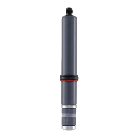
    Typ 8232 Beschreibung BeschreiBung 5.2. Kenntnis des sensors PG7 Kabelver- 4-poliger 5.1. Vorgesehener einsatzbereich Dichtung schraubung Stecker mit Kabel (separat • Die Sensoren Typ 8232 mit einem 4-20 mA Ausgang werden zur bestellt) Messung der Chlorkonzentration in Flüssigkeiten verwendet. Kappe für Klemmenleiste • Der Sensor Typ 8232 mit 0-2 V Ausgang wird zur Messung sehr Schaft Sprengring niedriger Chlorkonzentrationen in Flüssigkeiten verwendet. Der Sensor muss in einer Analyse-Messkammer Typ 8200 installiert Klemmenleiste werden. Gleitring Gegenelektrode Schaft Dichtungen Innerer Halter ("G-holder") Referenzelek- trode Schlauchring...
  • Seite 41: Technische Daten

    Typ 8232 TechnischeDaten Technische DaTen 6.1. Betriebsbedingungen Umgebungstemperatur Für Sensoren mit Bestell-Nr. 565164: +5 bis +40 °C Für Sensoren mit Bestell-Nr. 566051 und 566052: +5 bis +45 °C Luftfeuchtigkeit < 90 %, nicht kondensierend Höhe über Max. 2000 m Meeresspiegel 6.2. einhaltung von normen und richtlinien Durch folgende Normen wird die Konformität mit den EG-Richtlinien erfüllt: EMV: EN 61326-1. 6.3. allgemeine technische Daten 566051 566052 565164 Typ der Flüssigkeit • Schwimmbadwasser, Trink- • Schwimmbadwasser, Trink- Wasser mit ähnlichen Eigen- wasser, Brauchwasser, wasser, Meerwasser schaften wie Trinkwasser Prozesswasser • Tenside können teilweise tole- • Im Messwasser dürfen keine...
  • Seite 42: Mechanische Daten

    Typ 8232 TechnischeDaten Flüssigkeit pH-Bereich 6-8 pH 4-9 pH 6,5-9 pH Durchfluss ca. 30 l/h ca. 30 l/h ca. 30 l/h Temperaturkompensation automatisch, durch integrierten automatisch, durch integrierten automatisch, durch integrierten Temperatursensor Temperatursensor Temperatursensor Messbereich bei nominaler 0,01...20 ppm 0,01...20 ppm 0.005...2 ppm Steigung Ansprechzeit (t90) 30 s 120 s 120 s 6.4. mechanische Daten Werkstoffe Teil 566051 566052 565164 PG7 Kabelverschraubung Kappe für Klemmenleiste Schaft Membran PVC-U (semipermeable hydro- Mikroporöse hydrophile...
  • Seite 43: Elektrische Daten

    Typ 8232 TechnischeDaten Werkstoffe Teil 566051 566052 565164 Membrankappe Membran-Halter PEEK PEEK Stecker Innerer Halter 6.5. elektrische Daten 566051 566052 565164 Betriebsspannung 12-30 V DC (durch abgesetzten 12-30 V DC (durch abgesetzten 22,5-26 V DC Controller) Controller) Eigenverbrauch 4 mA 4 mA 20 mA Galvanische Trennung Spannungsausgang 0-2 V Stromausgang 4-20 mA 4-20 mA • Anschluss • 2-Leiter-System • 2-Leiter-System...
  • Seite 44: Installation Und Verkabelung

    Typ 8232 InstallationundVerkabelung insTallaTion unD Gefahr! VerKaBelung Verletzungsgefahr durch stromschlag! Zur Installation des Sensors in einem Rohr die folgenden Schritte • Schalten Sie vor Beginn der Arbeiten in jedem Fall alle ausführen: existierenden am Gerät angeschlossenen Spannungsver- sorgungen ab, und sichern Sie diese vor unbeabsichtigtem Den Sensor vorbereiten. Siehe Kap. 7.2. Wiedereinschalten! Den Sensor in der Analyse-Messkammer Typ 8200 installieren. • Beachten Sie die geltenden Unfallverhütungs- und Sicherheits- Siehe Kap. 7.3. bestimmungen für elektrische Geräte! Den Sensor an den Transmitter/Controller anschließen (z. B. Verletzungsgefahr durch hohen Druck in der anlage! Typ 8619). Siehe die Bedienungsanleitung des Transmitters/ • Vor dem Lösen der Prozessanschlüsse die Anlage druckfrei Controllers Typ 8619 und das Kap. 7.4. schalten und die Flüssigkeitszirkulation stoppen. Verletzungsgefahr aufgrund der art der Flüssigkeit! 7.1. sicherheitshinweise • Beachten Sie die Regeln, die auf dem Gebiet der Unfallver- hütung und der Sicherheit in Kraft sind und die sich auf die Gefahr! Verwendung gefährlicher Produkte beziehen. Verletzungsgefahr aufgrund der art des elektrolyt! • Beachten Sie die Warnungen auf der Elektrolytflasche. • Beim Umgang mit dem Sensor und dem Elektrolyt Handschuhe tragen, deren Material mit dem verwendeten Elektrolyt kompati- bel ist.
  • Seite 45: Vorbereiten Des Sensors Vor Der Installation Im Rohr

    Typ 8232 InstallationundVerkabelung 7.2. Vorbereiten des sensors vor der WarnunG! installation im rohr gefahr der membranbeschädigung durch Kontamination der membran mit Feststoffpartikeln und ablagerungen, die somit • Die GEL-Elektrolytflasche nicht schütteln, um Blasenbildung zu falschen messwerten führen können. zu vermeiden. • Vermeiden Sie jeglichen Kontakt der Membran mit Feststoffpar- • Die GEL-Elektrolytflasche nach dem Öffnen mit dem Kopf tikeln und Ablagerungen wie beispielsweise Sand. nach unten auf dem geschlossenen Auslass lagern. Verletzungsgefahr bei unsachgemäßer montage! • Reste des GEL-Elektrolyts auf der Arbeitselektrode und der • Die Montage darf nur durch autorisiertes Fachpersonal und mit Membrankappe mit warmem Wasser abspülen. geeignetem Werkzeug durchgeführt werden! Verletzungsgefahr durch ungewolltes einschalten der anlage und unkontrollierten wiederanlauf! • Anlage vor unbeabsichtigtem Betätigen sichern. • Nach jedem Eingriff am Sensor einen kontrollierten Wiederan- lauf gewährleisten. Die Messwerte können insbesondere dann falsch sein,...
  • Seite 46 Typ 8232 InstallationundVerkabelung 566051 Hinweise 566052 und 565164 Gefahr der Membranbeschädigung durch das Vakuum in der Ventil- Membrankappe. Ventil- öffnung öffnung → Vor dem Füllen der Membrankappe die Ventilöffnung durch Her- unterschieben des Schlauchrings freilegen, um eine Belüftung zu Schlauch- Schlauch-ring ermöglichen. ring Bei Auslieferung ist die Membrankappe nicht fest auf den Schaft geschraubt. • Die Referenzelektrode und die Arbeitselektrode nicht berühren. • Die Referenzelektrode nicht polieren.
  • Seite 47 Typ 8232 InstallationundVerkabelung 566051 Hinweise 566052 und 565164 Versionen mit dem inneren Halter: Den inneren Halter vorsichtig mit dem Elektrolyt auffüllen Prüfen, dass keine Luft (Blasen) im inneren Halter sind. Vorgang — gegebenenfalls wiederholen. Den Schaft aufrecht halten und die Arbeitselektrode vorsichtig in den gefüllten inneren Halter drücken. — Prüfen, ob an der spezifischen Membran des inneren Halters Luft- blasen erkennbar sind. Falls Luftblasen vorhanden sind, den inneren Halter vom Schaft ent- fernen, die innere Kappe, falls erforderlich, vorsichtig mit sauberem — Wasser spülen und die spezifische Membran der inneren Kappe mit einem saugfähigen Papiertuch trocknen. Die Anweisungen 1 bis 4 solange wiederholen, bis keinerlei Luft in der inneren Kappe mehr vorhanden ist. deutsch...
  • Seite 48 Typ 8232 InstallationundVerkabelung 566051 Hinweise 566052 und 565164 → Den Schaft aufrecht halten und langsam in die gefüllte Membrankappe setzen. → Die Membrankappe halten und den Schaft langsam im Uhrzeigersinn auf die Membrankappe schrauben. Wenn aufgrund der Dichtung ein Widerstand spürbar wird, das Schrauben fortsetzen, bis die Arbeitse- lektrode und der Boden der Membrankappe sich berühren: eine konvexe Wölbung der Membran ist erkennbar. → Stellen Sie sicher, dass der Schaft und der Membrankappe fest mit- einander Verbunden sind: - Nicht die Finger über die Ventilöffnung legen, da überschüssiger Elektrolyt durch den Auslass abfließen muss; - die Membran ist nach außen konvex gewölbt: die Membran nicht berühren oder stoßen. Mit der Membran nirgends anstoßen, an- dernfalls wird sie beschädigt und unbenutzbar. → Überschüssigen Elektrolyt mit einem mit Wasser befeuchteten Tuch entfernen. → Die Ventilöffnung mit dem Schlauchring abdecken. deutsch...
  • Seite 49: Montage Des Sensors In Der Analyse-Messkammer Typ 8200

    Typ 8232 InstallationundVerkabelung 7.3. montage des sensors in der 7.3.2. installation des sensors analyse-messkammer Typ 8200 → Das System druckfrei schalten. → Die Einbau-Überwurfmutter der Analyse-Messkammer Typ 8200 Gefahr! lösen. → gefahr der Beschädigung des sensors aufgrund hoher tem- Sicherstellen, dass der Sprengring, der Gleitring und die peraturen oder Drücke. Dichtung sich in ihrer korrekten Position am Sensor befinden. • Die Druck- und Temperaturbereiche des Sensors beachten. → Den Sensor in die Analyse-Messkammer Typ 8200 einsetzen. → Die Einbau-Überwurfmutter auf den Sensor setzen und fest auf • Das Wassereinlass-Kugelventil der Analyse-Messkammer die Analyse-Messkammer schrauben. Typ 8200 schließen. → Das Einlass-Kugelventil vorsichtig öffnen, sodass der • Installationen vermeiden, bei denen Luftblasen in das zu Schwimmer gerade das obere Ende der Durchflussanzeige messende Wasser gelangen können. Luftblasen an der...
  • Seite 50: Verdrahtung Des Sensors

    Typ 8232 InstallationundVerkabelung 7.4. Verdrahtung des sensors Sprengring 7.4.1. Verdrahtung der sensoren mit den Bestell-nummern 566051 und Gleitring 566052 Dichtung Die Sensoren mit den Bestell-Nummern 566051 und 566052 haben einen 4-20 mA Stromausgang. Der Sensor wird elektrisch vom Transmitter/Controller gespeist, mit dem der Sensor verbunden ist. Einbau-Über- Probeventil wurfmutter für DPD- Messung Negative Positive Versorgungsspannung Versorgungsspannung Wasserauslass Bild 3: Anschlussbelegung der Sensoren mit den Bestell- Nummern 566051 und 566052 →...
  • Seite 51: Verdrahtung Des Sensors Mit Der Bestell-Nummer 565164

    Typ 8232 InstallationundVerkabelung Den Sensor gemäß Bild 3 und der Anleitung des Trans- Leiterfarbe Signal mitters/Controllers anschließen. Siehe die entsprechende Braun Negative Versorgungsspannung Bedienungsanleitung. Das Kabel so weit herausziehen, dass es nicht die Innenseite der negative Signalspan- positive Kappe für die Klemmenleiste blockiert. nung Signalspannung Die Kappe für die Klemmenleiste von Hand festziehen. Die Mutter der Kabelverschraubung von Hand festziehen. 7.4.2. Verdrahtung des sensors mit der Bestell-nummer 565164 hinWeis: gefahr der Beschädigung des sensors aufgrund der stromversorgung. negative Versorgungs- positive Versorgungsspannung spannung • Stellen Sie sicher, dass die Versorgungsspannung im Bereich von 22,5 bis 26 V DC liegt. Bild 4: Anschlussbelegung des Sensors mit der Bestell-Nummer Der Sensor mit der Bestell-Nummer 565164 hat einen 0-2 V Ausgang.
  • Seite 52: Inbetriebnahme

    Typ 8232 Inbetriebnahme inBeTrieBnahme 8.2. inbetriebnahme des sensors mit der Bestell-nummer 565164 Wenn sich direkt auf der Membran Blasen befinden, erhöhen Zur Durchführung der Steigungskalibration muss das Mess- Sie vorübergehend den Durchfluss, um sie zu entfernen. wasser Chlor enthalten. Andernfalls ist der Einsatz einer speziellen Vorrichtung zur Kalibration erforderlich. 8.1. inbetriebnahme der sensoren Wenn keine Steigungskalibrierung durchgeführt ist, kann die mit den Bestell-nummern Chlorkonzentration nicht gemessen werden. Somit kann der 566051 und 566052 Chlorsensor nur zur Bestimmung der Anwesenheit bzw. des Vor der Inbetriebnahme: Fehlens von Chlor in der Flüssigkeit verwendet werden. Den Messwasserauslass der Analyse-Messkammer öffnen. Vor der Inbetriebnahme: Die Messwasserzufuhr langsam öffnen. Es wird ein Durchfluss Den Messwasserauslass öffnen. von 30 l/h empfohlen. Die Messwasserzufuhr langsam öffnen. Es wird ein Durchfluss von 30 l/h empfohlen. In der Bedienungsanleitung des Transmitters/Controllers Typ 8619: Den Sensor 24 Stunden arbeiten lassen. (6 Stunden nach a) Menü "Parameter"...
  • Seite 53: Wartung, Fehlerbehebung

    Typ 8232 Wartung,Fehlerbehebung warTung, Gefahr! FehlerBeheBung Verletzungsgefahr aufgrund der art des elektrolyt! • Beachten Sie die Warnungen auf der Elektrolytflasche. 9.1. sicherheitshinweise • Beim Umgang mit dem Sensor und dem Elektrolyt Handschuhe tragen, deren Material mit dem verwendeten Elektrolyt kompati- Gefahr! bel ist. • Den Elektrolyt nicht verschlucken. gefahr durch elektrische spannung! • Augen- und Hautkontakt mit dem Elektrolyt vermeiden. Bei jegli- • Beachten Sie die geltenden Unfallverhütungs- und Sicherheits- chem Augenkontakt mit dem Elektrolyt mit viel fließendem Was- bestimmungen für elektrische Geräte! ser ausspülen. Bei Augenentzündung einen Arzt hinzuziehen. Verletzungsgefahr durch hohen Druck in der anlage! • Vor dem Lösen der Prozessanschlüsse die Anlage druckfrei 9.2. regelmäßige wartungsarbeiten schalten und die Flüssigkeitszirkulation stoppen. Verletzungsgefahr aufgrund der art der Flüssigkeit! • Die braune oder graue Beschichtung der Referenz- • Beachten Sie die Regeln, die auf dem Gebiet der Unfallver- elektrode nicht entfernen, da andernfalls die Elektrode hütung und der Sicherheit in Kraft sind und die sich auf die beschädigt wird (aus PEEK).
  • Seite 54: Zusätzliche Wartungsarbeiten

    Typ 8232 Wartung,Fehlerbehebung → 9.3. Zusätzliche wartungsarbeiten Den alten Elektrolyt aus der Membrankappe ausgießen. → Bei Sensoren mit einem inneren Halter muss auch der Elektrolyt des inneren Halters ausgewechselt werden: 9.3.1. Dichtheit der membrankappe prüfen Den inneren Halter mit einer Pinzette aus der Membrankappe Nachdem die Membrankappe ausgetauscht und der Elektrolyt entfernen. gewechselt wurde, die Dichtheit der Membrankappe überprüfen. Den inneren Halter abspülen und auf einem sauberen, saugfä- Die Außenseite der Membrankappe gründlich trocknen. higen Papiertuch trocknen. → Die Membrankappe vorbereiten und mit Elektrolyt füllen, siehe Die Arbeitselektrode mit einem sauberen, trockenen Papiertuch Kap. 7.2. reinigen. → Falls erforderlich, die Außenseite der Membrankappe erneut Die Spitze der trockenen Arbeitselektrode reinigen: reinigen und trocknen. Das mitgelieferte Schleifpapier auf ein Papiertuch legen. Die Den Schaft langsam und vorsichtig auf die Membrankappe raue Seite muss oben liegen. schrauben, siehe Kap. 7.2. Den Schaft mit einer Hand aufrecht über dem Schleifpapier Falls mehrere Tropfen Elektrolyt aus der Membran kommen, ist halten. die Membran beschädigt. Die Membrankappe durch eine neue Das Schleifpapier an einer Ecke festhalten und die Spitze der ersetzen.
  • Seite 55: Membrankappe Auswechseln

    Typ 8232 Wartung,Fehlerbehebung 9.3.3. membrankappe auswechseln Sensor mit Bestell- Sensoren mit Bestell- Nummer 566051 Nummern 565164 und Membrankappe auswechseln: 566052 • einmal jährlich; • wenn die Steigungskalibrierung aufgrund instabiler oder zu niedriger angezeigter Werte nicht möglich ist. → Die Membrankappe abschrauben. → Den alten Elektrolyt aus der Membrankappe ausgießen. → Die Arbeitselektrode mit einem sauberen, trockenen Papiertuch reinigen. → Die Membrankappe mit dem Elektrolyt füllen, wie in Kap 7.2 → Bei den Sensoren ohne inneren Halter eine neue Membrankappe beschrieben. nehmen und mit Elektrolyt füllen. Siehe Kap. 7.2. → Bei den Sensoren mit innerem Halter den inneren Halter mit → Bei den Sensoren mit innerem Halter eine neue Membrankappe Elektrolyt füllen, siehe Beschreibung in Kap. 7.2. und einen neuen inneren Halter nehmen und sie mit Elektrolyt → Dichtheit der Membrankappe prüfen. Siehe Kap. 9.3.1. füllen. Siehe Kap. 7.2. →...
  • Seite 56: Fehlerbehebung

    Typ 8232 Wartung,Fehlerbehebung 9.4. Fehlerbehebung Eine Probe des Messwassers nehmen. Die Chlorkonzentration der Probe mit der DPD-1 Methode messen. 9.4.1. leD-Kodierung des sensors mit der Den erhaltenen Wert mit dem vom Sensor gemessenen Wert Bestell-nummer 565164 vergleichen. Der Status des Sensors wird durch eine orangefarbene LED und Wenn der erhaltene Wert sich dem mit dem Sensor gemessenen eine grüne LED angezeigt: Wert annähert, arbeitet der Sensor korrekt. Wenn die beiden Bedeutung Empfohlene Maßnahmen Werte verschieden sind, eine Steigungskalibrierung durchführen. LED-Status (Siehe Kap.8) Grün Ordnungsgemäßer → Wenn das Messwasser chlorfrei ist, eine externe Kalibrierung mit Sensorbetrieb — dem externen Kalibriergerät durchführen: Eine 250 ml Probe des Messwassers in ein Becherglas mit AUS Versorgungs- → einem Magnetrührstab füllen. Die Versorgungs-...
  • Seite 57: Problembehandlung

    Typ 8232 Wartung,Fehlerbehebung 9.4.2. Problembehandlung Problem Ursache Empfohlene Maßnahmen → Die Steigungs- Einlaufzeit zu kurz Für die Einlaufzeit siehe Kap. 8. → kalibrierung kann Die Kalibrierung wiederholen, nachdem die Einlaufzeit abgelaufen ist. nicht durchgeführt → Membran gebrochen Membrankappe auswechseln, siehe Kap. 9.3.3. werden, weil der → Messwert vom Membrankappe beschädigt Membrankappe auswechseln, siehe Kap. 9.3.3. DPD-Messwert → Ablagerungen auf der Membran Membrankappe auswechseln, siehe Kap. 9.3.3. abweicht → Störsubstanzen im Messwasser Das Messwasser auf störende Substanzen untersuchen. → Falls erforderlich, Bürkert kontaktieren. → Kurzschluss oder defekte Kurzschluss beheben. → Anschlusskabel. Falls erforderlich, die Anschlusskabel auswechseln.
  • Seite 58 Typ 8232 Wartung,Fehlerbehebung Problem Ursache Empfohlene Maßnahmen → Instabiles Membran gebrochen Membran auswechseln, siehe Kap. 9.3.3. Messsignal → Blasen im Elektrolyt Die Membrankappe leeren und wieder mit neuem Elektrolyt ohne Blasen füllen, siehe Kap. 9.3.2. → Gasblasen direkt auf der Membran Durchfluss vorübergehend erhöhen. → Falls erforderlich, die Installation überprüfen und korrigieren. → Die Originalfarbe (braun oder grau) Den Sensor an Bürkert zurücksenden. der Referenzelektrode wird weiß oder silbrig-glänzend → Ausgangssignal Der Sensor ist nicht richtig an den Den Sensor ordnungsgemäß an den Transmitter/Controller Typ 8619 beträgt 0 mA (nur Transmitter/Controller angeschlossen. anschließen. bei Sensoren mit → Die Anschlusskabel sind defekt. Die Kabel auswechseln. 4-20 mA Ausgang) → Der Transmitter/Controller Typ 8619 ist Den Transmitter/Controller Typ 8619 überprüfen.
  • Seite 59: Wenn Die Steigungskalibrierung Misslingt

    Typ 8232 Wartung,Fehlerbehebung 9.4.3. wenn die steigungskalibrierung Wenn der angezeigte Wert signifikant von +/- 0 mV bzw. +/- 4 mA abweicht, den Sensor an Bürkert zurücksenden. misslingt Wenn der angezeigte Wert +/- 0 mV bzw. +/- 4 mA beträgt, Falls die Steigungskalibrierung nicht durchgeführt werden kann: arbeitet die Sensorelektronik korrekt. Den Nullpunkt prüfen. • wegen der Abweichung des Messwerts vom DPD-Messwert, Siehe Kap. 9.4.5. siehe Kap. 9.4.2; • bei anderen Ursachen wie folgt vorgehen: 9.4.5. nullpunkt des sensors prüfen Korrekten Betrieb der Sensorelektronik überprüfen, siehe Den Sensor vorbereiten, siehe Kap. 7.2. Kap. 9.4.4. Den Sensor an den Transmitter/Controller Typ 8619 Nullpunktprüfung durchführen, siehe Kap. 9.4.5. anschließen. Das Signal prüfen, siehe Kap. 9.4.6. Ein Becherglas mit sauberem Leitungswasser füllen, das kein Wenn die drei vorangehenden Prüfungen durchgeführt wurden Desinfektionsmittel enthält. und das Problem weiterhin besteht, die zusätzlichen Prüfungen Den Sensor im Becherglas platzieren. durchführen, siehe Kap. 9.4.7. Mit dem Sensor 30 s im Becherglas rühren und sicherstellen, dass keine Blasen vorhanden sind. 9.4.4.
  • Seite 60: Signal Überprüfen

    Typ 8232 Wartung,Fehlerbehebung → 10. W enn sich der angezeigte Wert nach den Wartungsmaßnahmen Die Eignung des Sensors für den Prozess überprüfen; → immer noch nicht 0 V oder 4 mA nähert, den Sensor an Bürkert den Durchfluss prüfen; zurücksenden. → den pH-Wert des Messwassers prüfen; → die Temperatur des Messwassers prüfen; 9.4.6. signal überprüfen → sicherstellen, dass der Druck des Messwassers konstant ist und Wenn der Sensor den Nullpunkt korrekt misst (siehe Kap. 9.4.4 im zulässigen Bereich des verwendeten Sensors liegt; und 9.4.5), zum Prüfen des Signals die folgenden Maßnahmen → die Anschlusskabel überprüfen; durchführen: → sicherstellen, dass vor der Steigungskalibrierung die Einlaufzeit Etwas Chlor zu dem mit sauberem Leitungswasser gefüllten abgewartet wurde; Becherglas (aus Abschnitt "Nullpunktprüfung") hinzugeben. → die Konzentration des Desinfektionsmittels im Messwasser Mit dem immer noch an den Transmitter/Controller Typ 8619 überprüfen; angeschlossenen Sensor mindestens 5 min kontinuierlich rühren. → die Dosiereinheit überprüfen, falls vorhanden; Wenn das Sensorsignal ansteigt, arbeitet der Sensor korrekt.
  • Seite 61: Ersatzteile Und Zubehör

    Typ 8232 ErsatzteileundZubehör ersaTZTeile unD ZuBehör 10.2. Zubehör achtunG! Zubehör Bestell-nummer 4-poliger Stecker mit Kabel 565385 Verletzungsgefahr, sachschäden durch ungeeignete teile! Photometer MD100, Messbe- Falsches Zubehör und ungeeignete Ersatzteile können Ver- 566393 reich 0,01...6 ppm letzungen und Schäden am Sensor und dessen Umgebung verursachen. DPD-1 Reagenz (100 566394 Tabletten) • Nur Originalzubehör und Originalersatzteile von Bürkert verwenden. Externes Kalibriergerät 565163 Das externe Kalibriergerät wird nur gebraucht, wenn das Mess- 10.1. ersatzteile wasser kein Chlor enthält. Bestell- 566052 565164 566051 nummer VerPacKung, TransPorT ECS2.1/GEL,...
  • Seite 62: Lagerung

    Typ 8232 Lagerung lagerung Membrankappe verwenden (siehe Kap. 9.3.2 und Kap. 9.3.3). hinWeis: enTsorgung Des sensors Falsche lagerung kann schäden am sensor verursachen! → Den Sensor und seine Verpackung umweltfreundlich entsorgen. Lagern Sie den Sensor trocken und staubfrei! • Lagerungstemperatur des Sensors mit der Bestell-Nummer hinWeis: 565164: +5 bis +40 °C. umweltschäden durch sensoren, die durch Flüssigkeiten • Lagerungstemperatur der Sensoren mit den Bestell-Nummern kontaminiert sind. 566051 oder 566052: +5 bis +45 °C. • Die geltenden Bestimmungen über Abfallentsorgung und • Membrankappen, die mindestens 1 Tag lang benutzt wurden, Umweltschutz einhalten. nicht lagern oder wiederverwenden. • Die auf der Elektrolytflasche angegebene Lagerungstemperatur einhalten. Beachten Sie die nationalen Abfallbeseitigungsvorschriften. → Zum Lagern des Sensors: Die Membrankappe vom Schaft abschrauben. Die Referenzelektrode in sauberem Wasser abspülen: Die Elektroden nicht berühren oder reiben. An einem staubfreien Ort trocknen lassen. Die Membrankappe in sauberem Wasser abspülen und an einem staubfreien Ort auf einem saugfähigem Papier trocknen lassen. Bei den Sensoren mit den Bestell-Nummern 566052 und 565164 den inneren Halter von der Membrankappe entfernen, in sauberem Wasser abspülen und separat auf einem saugfähigen...
  • Seite 64 www.burkert.com...
  • Seite 65 Type 8232 Capteur de chlore Manuel d'utilisation Français...
  • Seite 66 Sous réserve de modifications techniques. © Bürkert SAS, 2014 Manuel d'utilisation 1407/00_EU-ML 00566160 / Original FR...
  • Seite 67 Type 8232  1. À propos de ce manuel ..............3 7.1. consignes de sécurité ..............10 1.1. symboles utilisés ................3 7.2. préparer le capteur avant de l'installer dans la conduite ....................11 1.2. définition du terme "capteur" ............3 7.3. installer le capteur dans la chambre de mesure 2. utilisation conforme................4 d'analyse type 8200 ................ 15 7.3.1. Installation de la chambre de mesure d'analyse 3. consignes de sécurité de base ............4 type 8200................15 4. informations générales ..............5 7.3.2. Installation du capteur ............15 4.1. contacts internationaux ..............5...
  • Seite 68 Type 8232  9.3.2. Changement de l'électrolyte ..........20 9.3.3. Changement du capuchon porte-membrane ....22 9.3.4. Vérifier le signal de mesure en cours de fonc- tionnement ................22 9.4. dépannage ..................23 9.4.1. Signal du voyant sur le capteur avec références de commande 565164 ............23 9.4.2. En cas de problème ............24 9.4.3. Si l'étalonnage de la pente échoue ........26 9.4.4. Vérifier le bon fonctionnement du système élec- tronique du capteur ............26 9.4.5. Vérifier le point zéro du capteur ........26 9.4.6. Vérification du signal............27 9.4.7. Vérifications supplémentaires ...........27 10. pièces de rechange et accessoires ....... 28 10.1. pièces de rechange .
  • Seite 69: À Propos De Ce Manuel

    Type 8232 Àproposdecemanuel À propos de ce manuel attention Ce manuel décrit le cycle de vie complet du capteur. Conservez-le met en garde contre un risque éventuel. de sorte qu’il soit accessible à tout utilisateur et à disposition de tout • Son non-respect peut entraîner des blessures légères ou de nouveau propriétaire. gravité moyenne. ce manuel contient des informations importantes relatives à remarque la sécurité. met en garde contre des dommages matériels. Le non-respect de ces consignes peut entraîner des situations • Le non-respect de cet avertissement peut entraîner des dom- dangereuses. mages sur le capteur ou système. • Ce manuel d'utilisation doit être lu et compris. désigne des informations supplémentaires, des conseils ou 1.1. symboles utilisés des recommandations importants. danger Renvoie à des informations contenues dans ce manuel d'utilisation ou dans d‘autres documents. met en garde contre un danger imminent. • Son non-respect peut entraîner la mort ou de graves blessures. → indique une opération à effectuer.
  • Seite 70: Utilisation Conforme

    Type 8232 Utilisationconforme uTilisaTion conforme consignes de sécuriTé de base l‘utilisation non conforme du capteur peut présenter des Ces consignes de sécurité ne tiennent pas compte : dangers pour les personnes, les installations proches et • des imprévus pouvant survenir lors de l’assemblage, de l’utilisation l‘environnement. et de l’entretien des appareils. • Les capteurs 8232 avec une sortie 4-20 mA sont utilisés pour • des prescriptions de sécurité locales que l’exploitant est tenu de faire mesurer la concentration de chlore libre dans l'eau. respecter par le personnel chargé de l’assemblage et de l’entretien. • Le capteur 8232 avec une sortie 0-2 V est utilisé pour mesurer la concentration de chlore dans l'eau à des concentrations très faibles. • Utiliser le capteur conformément aux caractéristiques et danger dû à la tension électrique conditions de mise en service et d'utilisation indiqués dans les danger dû à la pression élevée dans l'installation. documents contractuels et dans le présent manuel d'utilisation. danger dû à la nature du fluide. • L'utilisation en toute sécurité et sans problème du capteur repose sur un transport, un stockage et une installation corrects ainsi que sur une utilisation et une maintenance effectuées avec soin. situations dangereuses diverses • Veiller à toujours utiliser ce capteur de façon conforme.
  • Seite 71: Informations Générales

    Type 8232 Informationsgénérales informaTions générales situations dangereuses diverses 4.1. contacts internationaux Pour éviter toute blessure, veiller à : Nous contacter : • respecter les règles techniques générales lors de l'installation et de l'utilisation du capteur. Bürkert SAS • ne pas utiliser le capteur dans une atmosphère explosible. Rue du Giessen • Ne pas utiliser de fluide incompatible avec les matériaux com- BP 21 posant F-67220 TRIEMBACH-AU-VAL le capteur. Vous pouvez également contacter votre revendeur Bürkert. • ne pas utiliser le capteur dans un environnement incompatible avec les matériaux qui le composent. Les adresses des filiales internationales sont disponibles • ne pas soumettre le capteur à des charges mécaniques (par ex. sous : www.burkert.com en y déposant des objets ou en l’utilisant comme marchepied). • n’apporter aucune modification au capteur, intérieure ou 4.2. conditions de garantie extérieure.
  • Seite 72: Description

    Type 8232 Description descripTion 5.2. connaître le capteur presse-étoupe 5.1. secteur d’application Connecteur à joint 4 broches avec câble (commandé • Les capteurs 8232 avec une sortie 4-20 mA sont utilisés pour séparément) mesurer la concentration de chlore dans les fluides à analyser. capuchon du bornier • Le capteur 8232 avec une sortie 0-2 V est utilisé pour mesurer la bague de armature butée concentration de chlore dans les fluides à des concentrations très faibles. bornier Le capteur doit être installé dans une chambre de mesure d'analyse type 8200. bague contre-électrode coulissante armature joints support interne ("G-holder") électrode de manchon référence...
  • Seite 73: Caractéristiques Techniques

    Type 8232 Caractéristiquestechniques caracTérisTiques Techniques 6.1. conditions en fonctionnement Température ambiante Pour les capteurs avec référence de commande 565164 : +5 à +40°C Pour les capteurs avec références de commande 566051 et 566052 : +5 à +45°C Humidité de l’air < 90%, non condensé Altitude absolue Max. 2000 m 6.2. conformité aux normes et directives La conformité du capteur aux directives CE est respectée par les normes suivantes : CEM : EN 61326-1. 6.3. caractéristiques techniques générales 566051 566052 565164 Type de fluide • eau de piscine, eau potable, • eau de piscine, eau potable, eau à qualité potable eau sanitaire, eau de process eau de mer • libre de tout agent tensioactif • les agents tensioactifs sont...
  • Seite 74: Caractéristiques Mécaniques

    Type 8232 Caractéristiquestechniques Compensation en température automatique, avec capteur de automatique, avec capteur de automatique, avec capteur de température intégré température intégré température intégré Plage de mesure à la pente 0,01...20 ppm 0,01...20 ppm 0,005...2 ppm nominale Temps de réponse (t90) 30 s 120 s 120 s 6.4. caractéristiques mécaniques Matériaux Élément 566051 566052 565164 Presse-étoupe PG7 Capuchon du bornier Armature Membrane PVC-U (membrane hydrophobe Membrane microporeuse hydro- Membrane microporeuse hydro- semi-perméable) phile, PVC, PEEK phile, PVC, PEEK Joints Bague de butée PETF...
  • Seite 75: Caractéristiques Électriques

    Type 8232 Caractéristiquestechniques Matériaux Élément 566051 566052 565164 Connecteur Support interne 6.5. caractéristiques électriques 566051 566052 565164 Tension d'alimentation 12-30 V DC (via un contrôleur 12-30 V DC (via un contrôleur 22,5-26 V DC déporté) déporté) Consommation propre 4 mA 4 mA 20 mA Isolation galvanique Sortie tension 0-2 V Sortie courant 4-20 mA 4-20 mA • Raccordement • Système 2 fils • Système 2 fils • Protection • contre les inversions de...
  • Seite 76: Installation Et Câblage

    Type 8232 Installationetcâblage insTallaTion eT câblage danger Suivre les étapes suivantes pour installer le capteur dans une risque de blessure par décharge électrique. conduite : • Couper l'alimentation de tous les conducteurs et consigner Préparer le capteur. Voir chap. 7.2. l'alimentation électrique avant d'intervenir sur l'installation. Installer le capteur dans la chambre de mesure d'analyse type • Respecter la règlementation en vigueur en matière de pré- vention des accidents et de sécurité relative aux appareils 8200. Voir chap. 7.3. électriques. Connecter le capteur au contrôleur déporté (type 8619 par risque de blessure dû à la pression élevée dans l'installation. exemple). Consulter le manuel d'utilisation du contrôleur type 8619 et le chap. 7.4. • Stopper la circulation du fluide, couper la pression et purger la canalisation avant de desserrer les raccordements du process. 7.1. consignes de sécurité risque de blessure dû à la nature du fluide. • Respecter la réglementation en vigueur en matière de préven- danger tion des accidents et de sécurité relative à l‘utilisation de fluides agressifs. risque de blessure dû à la nature de l'électrolyte. • Respecter les avertissements indiqués sur la bouteille d'électrolyte.
  • Seite 77: Préparer Le Capteur Avant De L'installer Dans La Conduite

    Type 8232 Installationetcâblage 7.2. préparer le capteur avant de avertissement l'installer dans la conduite risque d'endommagement de la membrane dû à la conta- mination de la membrane par des particules solides et des • Ne pas secouer la bouteille d'électrolyte gélifié pour éviter dépôts qui peut conduire à des signaux de mesures erronés. toute formation de bulles. • Éviter tout contact de la membrane avec des particules solides • Après ouverture, stocker la bouteille d'électrolyte gélifi, tête et des dépôts tel que le sable. vers le bas. risque de blessure dû à un assemblage non conforme. • Rincer à l'eau chaude les résidus de GEL-électrolyte sur • L'assemblage doit être effectué uniquement par du personnel l'électrode de travail et sur le capuchon porte-membrane.
  • Seite 78 Type 8232 Installationetcâblage 566051 Consignes 566052 & 565164 Risque d'endommagement de la membrane dû au vide dans le Orifice capuchon porte-membrane. Orifice d'aération d'aération → Avant de remplir le capuchon porte-membrane, découvrir l'orifice Manchon d'aération en baissant le manchon souple pour permettre la ventilation. Manchon souple souple Lors de la livraison, le capuchon porte-membrane n'est pas fermement vissé sur l'armature. • Ne pas toucher l'électrode de référence ni l'électrode de travail. • Ne pas frotter l'électrode de référence. • Ne pas ôter la couche brune ou grise de l'électrode de référence. → Dévisser le capuchon porte-membrane de l'armature et le placer sur un support propre. → Pour les capteurs munis d'un support interne, ôter le support interne de son emballage et poser le capuchon porte-membrane ainsi que le support interne séparément sur une base propre et non absorbante.
  • Seite 79 Type 8232 Installationetcâblage 566051 Consignes 566052 & 565164 Versions avec le support interne : Remplir avec précaution d'électrolyte le support interne. Vérifier qu'aucune bulle d'air ne se trouve dans le support interne. — Sinon, renouveler l'opération. Maintenir l'armature à la verticale et pousser avec précaution l'élec- trode de travail dans le support interne plein. — Vérifier si des bulles d'air sont visibles dans la membrane spécifique du support interne. Si des bulles d'air sont visibles, retirer le support interne de l'ar- mature et rincer le support interne avec précaution à l'eau claire et — sécher la membrane spécifique avec du papier absorbant. Répéter les consignes 1 à 5 jusqu'à ce qu'il n'y ait plus de bulles d'air. français...
  • Seite 80 Type 8232 Installationetcâblage 566051 Consignes 566052 & 565164 → Maintenir l'armature à la verticale et l'insérer lentement dans le capuchon porte-membrane rempli. → Tenir le capuchon porte-membrane et visser lentement l'armature dans le sens des aiguilles d'une montre sur le capuchon porte-membrane. Si le joint créé une résistance, continuer de visser jusqu'à ce que l'électrode de travail et le fond du capuchon porte-membrane soient en contact : la membrane aura une courbure convexe. → S'assurer que l'armature est fermement fixée au capuchon porte-membrane. - Ne pas mettre ses doigts sur l'orifice d'aération puisqu'un excédent d'électrolyte doit s'écouler à travers l'orifice d'aération ; - la membrane se courbe vers l'extérieur : ne pas toucher la mem- brane. Ne pas donner de coup à la membrane, autrement elle serait...
  • Seite 81: Installer Le Capteur Dans La Chambre De Mesure D'analyse Type 8200

    Type 8232 Installationetcâblage 7.3. installer le capteur dans la 7.3.2. installation du capteur chambre de mesure d'analyse → Dépressuriser le dispositif. type 8200 → Dévisser l'écrou de montage de la chambre de mesure d'analyse type 8200. danger → Vérifier que la bague de butée, la bague coulissante et le joint sont correctement positionnés sur le capteur. risque d'endommager le capteur dû à des températures → élevées ou à la pression. Insérer le capteur une fois préparé dans la chambre de mesure • Respecter la pression du capteur et les plages de températures. d'analyse type 8200. → Insérer l'écrou de montage dans le capteur et le visser fer- • Fermer la vanne à boisseau de l'arrivée d'eau de la mement à la chambre de mesure d'analyse.
  • Seite 82: Câblage Du Capteur

    Type 8232 Installationetcâblage 7.4. câblage du capteur bague de butée 7.4.1. cablâge des capteurs avec références de commande 566051 et bague coulissante 566052 joint Les capteurs avec références de commande 566051 et 566052 ont une sortie courant 4-20 mA. Le capteur est alimenté électriquement par le contrôleur déporté auquel le capteur est raccordé. écrou Vanne d'échantillon- nage pour la Alimentation électrique Alimentation électrique mesure DPD négative positive sortie d'eau Fig.
  • Seite 83: Câblage Du Capteur Avec Référence De Commande 565164

    Type 8232 Installationetcâblage Câbler le capteur selon la Fig. 3 et selon le contrôleur déporté. Couleur des fils Signal Consulter le manuel d'utilisation correspondant. Brun Alimentation électrique négative Tirer le câble afin qu'il ne bloque pas l'intérieur du capuchon du → Utiliser un câble dont la longueur max. est de 30 m. bornier. → Raccorder le capteur au contrôleur déporté type 8619. Serrer à la main le capuchon du bornier. Consulter le manuel d'utilisation correspondant. Serrer à la main l'écrou du presse-étoupe. signal de tension signal de tension négative positive 7.4.2. câblage du capteur avec référence de commande 565164 remarque risque d'endommagement du capteur dû à l'alimentation électrique. • S'assurer que la plage de l'alimentation électrique est de 22,5 à 26 V DC. Le capteur avec référence de commande 565164 a une sortie 0-2 alimentation électrique alimentation électrique négative...
  • Seite 84: Mise En Service

    Type 8232 Miseenservice mise en service b) Menu "Réglages" Mx: Entrées AI1 or AI2 Plage = 4-20 mA c) Saisir pour 4 mA: 0 et pour 20 mA: 20. Si des bulles se forment sur la membrane, augmenter temporai- rement le débit d'écoulement afin de les éliminer. Faire l'étalonnage de la pente avec le contrôleur déporté: consulter le manuel d'utilisation correspondant. → Si l'étalonnage de la pente ne peut pas se faire, voir chap. 9.4.3. 8.1. mise en service du capteur avec références de commande : 8.2. mise en service du capteur avec 566051et 566052 référence de commande 565164 Avant la mise en service: Ouvrir la sortie de l'eau analysée de la chambre de mesure...
  • Seite 85: Maintenance Et Dépannage

    Type 8232 Maintenanceetdépannage mainTenance eT Faire fonctionner le capteur pendant 24 heures. (6 heures après la maintenance/l'échange de l'électrolyte) dépannage Faire l'étalonnage de la pente avec le contrôleur déporté: consulter le manuel d'utilisation correspondant. 9.1. consignes de sécurité → Si l'étalonnage de la pente est impossible, voir chap. 9.4.3. danger risque de blessure dû à la tension électrique • Respecter la réglementation en vigueur en matière de pré- vention des accidents et de sécurité relative aux appareils électriques. risque de blessure dû à la pression élevée dans l'installation. • Stopper la circulation du fluide, couper la pression et purger la canalisation avant de desserrer les raccordements au process. risque de blessure dû à la nature du fluide. • Respecter la réglementation en vigueur en matière de préven- tion des accidents et de sécurité relative à l‘utilisation de fluides agressifs. français...
  • Seite 86: Opérations De Maintenance Régulières

    Type 8232 Maintenanceetdépannage 9.3. opérations de maintenance danger supplémentaires risque de blessure dû à la nature de l'électrolyte. • Respecter les avertissements indiqués sur la bouteille 9.3.1. vérifier l'étanchéité du capuchon d'électrolyte. porte-membrane • Porter des gants, dont la matière est compatible avec l'électro- lyte, pour manipuler le capteur et l'électrolyte. Une fois que le capuchon porte-membrane et l'électrolyte ont été • Ne pas avaler l'électrolyte. changés, vérifier l'étanchéité du capuchon porte-membrane. • Éviter tout contact de l'électrolyte avec la peau et les yeux. En Sécher minutieusement l'extérieur du capuchon cas de contact avec l'électrolyte, nettoyer abondamment à l'eau porte-membrane. courante. Contacter un médecin en cas d'inflammation de l'oeil. Préparer le capuchon porte-membrane et le remplir d'élec- trolyte, voir chap. 7.2. 9.2. opérations de maintenance Si nécessaire, nettoyer et sécher à nouveau l'extérieur du régulières capuchon porte-membrane.
  • Seite 87 Type 8232 Maintenanceetdépannage → Découvrir l'orifice d'aération en soulevant le manchon souple pour Capteur avec référence Capteurs avec références laisser passer l'air dans l'orifice d'aération. de commande 566051 de commande 565164 & → Dévisser le capuchon porte-membrane. 566052 → Vider l'ancien électrolyte du capuchon porte-membrane. → En ce qui concerne les capteurs ayant un support interne, l'élec- trolyte du support interne doit également être changé : Utiliser des pincettes pour ôter le support interne du capuchon porte-membrane. Rincer le support interne et le sécher sur du papier absorbant propre. → → Nettoyer l'électrode de travail avec une serviette en papier Remplir d'électrolyte le capuchon porte-membrane tel que décrit propre et sèche. dans le chap. 7.2. → → Nettoyer l'extrémité de l'électrode de travail séchée : En ce qui concerne les capteurs ayant un support interne, remplir d'électrolyte le support interne tel que décrit dans le Placer le papier abrasif fourni sur une serviette en papier. Le chap. 7.2. côté rugueux doit se trouver vers le haut. → Vérifier l'étanchéité du capuchon porte-membrane. Voir chap. Maintenir avec une main l'armature à la verticale au-dessus du 9.3.1.
  • Seite 88: Changement Du Capuchon Porte-Membrane

    Type 8232 Maintenanceetdépannage 9.3.3. changement du capuchon 9.3.4. vérifier le signal de mesure en porte-membrane cours de fonctionnement → Si l'eau analysée contient du chlore : Changer le capuchon porte-membrane Prendre un échantillon de l'eau analysée. • une fois par an ; Mesurer la concentration en chlore de l'échantillon en utilisant la • si l'étalonnage de la pente n'est pas possible dû à des méthode DPD-1. valeurs affichées instables ou trop basses. Comparer la valeur obtenue avec la valeur mesurée par le →...
  • Seite 89: Dépannage

    Type 8232 Maintenanceetdépannage DPD-1. État des Voyant Signification Actions recommandées Après l'étalonnage, remettre le capteur dans la chambre de voyants mesure d'analyse. Orange Le capteur éteint fonctionne — 9.4. dépannage correctement Le capteur n'est → 9.4.1. signal du voyant sur le capteur avec pas correctement Câbler le capteur allumé câblé. références de commande 565164 d'après le chap. 7. Un voyant orange et un voyant vert indiquent l'état du capteur : La concentration État des...
  • Seite 90: En Cas De Problème

    Type 8232 Maintenanceetdépannage 9.4.2. en cas de problème Problème Signification Actions recommandées → L'étalonnage de Durée de polarisation trop courte Pour la durée de polarisation, voir chap.8. → la pente ne peut Répéter l'étalonnage lorsque la durée de polarisation s'est écoulée. être effectué car → La membrane s'est fendu Remplacer le capuchon porte-membrane, voir chap 9.3.3. la valeur mesurée → dévie de la mesure Capuchon porte-membrane endommagé Remplacer le capuchon porte-membrane, voir chap 9.3.3. DPD. → Dépôts sur la membrane Remplacer le capuchon porte-membrane, voir chap 9.3.3. → Substances interférant dans l'eau Examiner l'eau analysée à la recherche de substances interférentes. → analysée Contacter Bürkert si nécessaire. → Il y a un court-circuit ou les câbles de Réparer le court-circuit.
  • Seite 91 Type 8232 Maintenanceetdépannage Problème Signification Actions recommandées → Le signal de La membrane s'est fendue Changer la membrane, voir chap 9.3.3. mesure n'est pas → Bulles dans l'électrolyte Vider le capuchon porte-membrane et le remplir à nouveau d'électrolyte stable sans bulles, voir chap 9.3.2. → Bulles de gaz sur la membrane Augmenter temporairement le débit d'écoulement. → Vérifier l'installation et la rectifier si nécessaire. → La couleur d'origine (brun ou gris) de Renvoyer le capteur à Bürkert. l'électrode de référence vire au blanc ou argent brillant → Le signal de Le capteur n'est pas correctement Raccorder correctement le capteur au contrôleur déporté type 8619. sortie est 0 mA câblé au contrôleur. (seulement les → Les câbles de raccordement sont Changer les câbles. capteurs avec une défectueux. sortie 4-20 mA) →...
  • Seite 92: Si L'étalonnage De La Pente Échoue

    Type 8232 Maintenanceetdépannage 9.4.3. si l'étalonnage de la pente échoue Si la valeur affichée dévie de manière significative de +/- 0 mV ou de +/- 4 mA, renvoyer le capteur à Bürkert. Si l'étalonnage de la pente ne peut pas se faire: Si la valeur affichée est soit +/- 0 mV soit +/- 4 mA, le système • car les valeurs mesurées dévient de la mesure DPD, voir chap. électronique du capteur fonctionne correctement. Vérifier le 9.4.2 ; point zéro. Voir chap. 9.4.5. • en ce qui concerne les autres causes, faire ce qui suit : Vérifier le bon fonctionnement de l'électronique du capteur, voir 9.4.5. vérifier le point zéro du capteur chap. 9.4.4. Préparer le capteur tel que décrit dans le chap. 7.2. Faire une vérification du point zéro, voir chap. 9.4.5. Raccorder le capteur au contrôleur déporté type 8619. Vérifier le signal, voir chap. 9.4.6. Remplir le bécher d'eau claire du robinet qui ne contient pas de Si les trois dernières vérifications ont été effectuées et que le désinfectant. problème persiste, faire les vérifications supplémentaires telles Placer le capteur dans le bécher. qu'indiquées dans le chap. 9.4.7.
  • Seite 93: Vérification Du Signal

    Type 8232 Maintenanceetdépannage → 10. Si même après les opérations de maintenance, la valeur affichée vérifier la valeur du pH de l'eau analysée ; → n'approche pas 0 V ou 4 mA, renvoyer le capteur à Bürkert. vérifier la température de l'eau analysée ; → s'assurer que la pression de l'eau analysée est constante et 9.4.6. vérification du signal qu'elle se trouve dans la plage autorisée du capteur utilisé ; → vérifier les câbles de raccordement ; Si le capteur mesure correctement le point zéro (voir chap. 9.4.4 et → 9.4.5), faire ce qui suit pour vérifier le signal : s'assurer que la durée de polarisation a été effectuée avant l'éta- lonnage de la pente ; Ajouter du chlore dans le bécher rempli d'eau claire du robinet → d'après la section "Vérification du point zéro". vérifier la concentration en désinfectant de l'eau analysée ; → Remuer sans s'arrêter pendant au moins 5 min. en utilisant le vérifier le dispositif de dosage le cas échéant ; capteur toujours raccordé au contrôleur déporté type 8619. → vérifier la concentration en désinfectant dans le réservoir de Si le signal du capteur augmente, le capteur fonctionne correc- dosage. tement. Effectuer les vérifications supplémentaires telles que décrites dans le chap. 9.4.7. Si le capteur ne réagit pas au chlore, effectuer les opérations de maintenance telles que décrites dans le chap. 9.2 et refaire une vérification du signal.
  • Seite 94: Pièces De Rechange Et Accessoires

    Type 8232 Piècesderechangeetaccessoires pièces de rechange eT 10.2. accessoires accessoires accessoire référence de commande attention Connecteur à 4 broches 565385 (avec câble) risque de blessures et de dommage matériel dus à l'utili- Photomètre MD100, plage de sation de pièces inadaptées. 566393 mesure 0,01...6 ppm Un mauvais accessoire et des pièces de rechange inadaptées Réactif DPD-1, 100 pastilles 566394 peuvent entraîner des blessures et endommager le capteur et son environnement. Appareil d'étalonnage 565163 • N'utiliser que les accessoires et les pièces de rechange de la externe société Bürkert. L'appareil d'étalonnage externe est seulement nécessaire lorsque l'eau analysée ne contient pas de chlore. 10.1. pièces de rechange référence emballage eT TransporT...
  • Seite 95: Stockage

    Type 8232 Stockage → sTockage Lors de l'utilisation du capteur après stockage, nettoyer l'ex- trémité de l'électrode avec le papier abrasif et utiliser un nouveau remarque capuchon porte-membrane (voir chap. 9.3.2 et chap. 9.3.3). un mauvais stockage peut endommager le capteur. • Stocker le capteur dans un endroit sec et à l'abri de la éliminaTion du capTeur poussière. → Mettre au rebut le capteur et l’emballage dans le respect de • Température de stockage pour le capteur avec références de l’environnement. commande 565164 : +5 à+40°C. • Température de stockage pour les capteurs avec références de remarque commande 566051 ou 566052 : +5 à +45°C. dommages à l'environnement causés par des capteurs • Ne pas stocker ou réutiliser les capuchons porte-membrane qui contaminés par des fluides.
  • Seite 96 Type 8232  français...
  • Seite 98 www.burkert.com...

Inhaltsverzeichnis