
Verwandte Anleitungen für bürkert 8223


Inhaltszusammenfassung für bürkert 8223
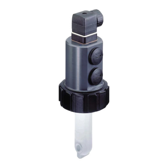
- Seite 1 8223 INDUCTIVE CONDUCTIVITY SENSOR Instruction Manual © Bürkert 2001 Subject to technical change without notice Downloaded from www.Manualslib.com manuals search engine...
-
Seite 2: Inhaltsverzeichnis
Electrical connection instructions ...............15 4.3.1 Mounting and connection of the EN 175301-803 connector ... 15 4.3.2 Connecting the 8223 to an external device (PLC,...) ........16 4.3.3 Precautions during installation and commissioning ........16 Examples of connections with a 8223 sensor ............17 MAINTENANCE ......................18... -
Seite 3: Introduction
If these instructions are ignored or the device is not used according to the specifications, no liability will be accepted and the guarantee on the device and accessories will become invalid. 8223 Downloaded from www.Manualslib.com manuals search engine... -
Seite 4: Quick Start
Press the push- every 2 s and current output must be out of button for 2 s indicates 4 mA? the fluid. See § 3.6 Install the appliance on the pipe See § 4.1 8223 Downloaded from www.Manualslib.com manuals search engine... - Seite 5 Measurement of a nil conductivity (< 2% of the full scale) Flashes at a fequency Measurement of a conductivity which is proportional to this frequency between 0,5 and 16 Hz See also § 5.2 for any other LED flashing. 8223 Downloaded from www.Manualslib.com manuals search engine...
-
Seite 6: Configuration
0 to 10 mS/cm (default value) 0 to 100 mS/cm 0 to 1 S/cm a 4 mA current indicates a conductivity which is equal to 0 mSiemens/cm (less than 2% of the selected full scale) 8223 Downloaded from www.Manualslib.com manuals search engine... - Seite 7 - If a fitting with a DN > 100 or a vessel is used, apply a correction factor = 1. Example: The 8223 sensor is installed in a PVDF S020 fitting with DN32. The selected full scale is FS = 10 mS/cm.
-
Seite 8: Measuring Range Of The Temperature
The value of the temperature which corresponds to a 20-mA current is always 80 °C If the 8223 has been programmed to transmit the temperature (and not the con duc - tiv i ty) on the 4-20 mA output (all SW2 switches are set to ON), the cor re spond ing temperature/4-20 mA-output curve is the following: °C... -
Seite 9: Filtering Level
CONFIGURATION 3.3 FILTERING LEVEL Filtering allows the attenuation of fluctuations in the conductivity. The 8223 sensor has four filtering levels, from 0 to 3: Level 0 corresponds to a nil filtering: the sensor indicates any conductivity variation Level 3 corresponds to the maximum filtering: the sensor smoothes the conductivity variations at the most Levels 1 and 2 correspond to intermediate filterings. -
Seite 10: Temperature Compensation
CONFIGURATION 3.4 TEMPERATURE COMPENSATION The conductivity varies with the temperature; To compensate the variations, the 8223 sensor measures the real conductivity and temperature of the fluid then re-calculates the conductivity corresponding to a temperature of 25 °C. SW2 makes it possible to choose the calculation mode of the temperature com pen sa tion. -
Seite 11: Linear Compensation
25 C 4) Use the compensation factor nearest to the calculated one: Position of the switches of SW2 Temperature compensation No compensation (default value) 0.1% 0.25% 0.5% 0.7% 1.5% NaOH NaCl Not used 8223 Downloaded from www.Manualslib.com manuals search engine... -
Seite 12: Transmission Of The Temperature
CONFIGURATION 3.5 TRANSMISSION OF THE TEMPERATURE If, instead of the conductivity, the 8223 sensor is meant to transmit the tem per a ture (be tween -10 °C and 80 °C) to the 4-20 mA output, configure SW2 as follows: Position of the switches of SW2... -
Seite 13: Installation
4.1 MOUNTING INSTRUCTIONS 4.1.1 Temperature-pressure diagram The sensor and the fitting in which it is installed have limited operating temperatures and pressures. The diagram hereunder shows the operating range of the 8223-fitting assem- bly, for each fitting material: P [bar]... -
Seite 14: Mounting
INSTALLATION 4.2 MOUNTING The 8223 conductivity sensor is installed on a pipe as follows: - Insert the nut [4] on the fitting [6] and clip the ring [3] in the groove [5]. - Insert the sensor [1] into the fitting [6] by ensuring the gasket [2] is in its right place. -
Seite 15: Electrical Connection Instructions
Replace part [3]. Tighten the cable gland [5]. Place gasket [4] between the connector and the fixed connector of the 8223. Connect the connector to the 8223. Tighten screw [1] to ensure tightness and correct electrical contact 4-20 mA output (12-30 VDC) -
Seite 16: Connecting The 8223 To An External Device (Plc
INSTALLATION 4.3.2 Connecting the 8223 to an external device (PLC,...) The 8223 sensor can be connected to a PLC or any other device which is able to use the 4-20 mA signal transmitted by the sensor. The connection can be carried out either in sourcing or in sinking mode, as shown by the... -
Seite 17: Examples Of Connections With A 8223 Sensor
INSTALLATION 4.4 EXAMPLES OF CONNECTIONS WITH A 8223 SENSOR not connected 8223 24 V= 1067 8223 Between the 8223 sensor and the 1067 not connected positioner. 4-20 mA 24 V= 24 V= + - + - 2031+ 8630 Between the 8223 sensor and a sole- noid valve with 8624-2 PI controller. -
Seite 18: Maintenance
MAINTENANCE 5.1 MAINTENANCE The 8223 sensor may be cleaned with water or a product which is compatible with the materials therein. Your Bürkert supplier is available to provide you with any additional information you require. 5.2 IF A PROBLEM OCCURS... - Seite 19 22 mA If the error persists, calibration failed briefly send the device every 2 s back to Burkert. Send the device flash simultaneously 22 mA The sensor is out of service back to Burkert 8223 Downloaded from www.Manualslib.com manuals search engine...
-
Seite 20: Technical Data
Electrical connection - Power supply voltage 12 to 30 VDC, filtered and regulated - Maximum current consumption 50 mA max. + 22 mA for the current output - Connector type EN 175301-803 8223 Downloaded from www.Manualslib.com manuals search engine... -
Seite 21: User Characteristics
- Housing material PEHD - Protection rating IP65, connector plugged in and tightened 6.6 CONFORMITY WITH STANDARDS Electromagnetic compatibility: - Emission EN 50081-1 (1992) - Protection EN 50082-2 (1995) - Safety EN 61010-1 8223 Downloaded from www.Manualslib.com manuals search engine... -
Seite 22: Dimensions (Mm)
TECHNICAL DATA 6.7 DIMENSIONS (MM) H (mm) DN (mm) Stainless steel T fitting Plastic spigot spigot 204.3 201.8 202.0 205.6 209.4 205.3 215.5 210.3 215.5 220.3 214.3 225.3 221.3 232.3 231.3 242.3 253.3 274.3 8223 Downloaded from www.Manualslib.com manuals search engine... -
Seite 23: Information
7.1 STANDARD DELIVERY The standard delivery comprises: - an 8223 sensor - a set with 1 EPDM gasket + 1 FKM gasket - an EN 175301-803 connector 7.2 ORDERING TABLE FOR SENSORS 8223 Output type Finger material Order code PVDF... -
Seite 24: Measurement Principle
7.4 MEASUREMENT PRINCIPLE Conductivity is the ability of a liquid / solution to conduct an electrical current. To measure the conductivity of a solution the 8223 conductivity sensor uses the following principle: - A voltage is connected to the primary magnetic coil. - Seite 25 INFORMATION 8223 Downloaded from www.Manualslib.com manuals search engine...
-
Seite 26: Declaration Of Conformity
INFORMATION 7.6 DECLARATION OF CONFORMITY 8223 Downloaded from www.Manualslib.com manuals search engine... - Seite 27 8223 CAPTEUR DE CONDUCTIVITÉ PAR INDUCTION Manuel utilisateur © Bürkert 2001 Sous réserve de mo di fi ca tions techniques Downloaded from www.Manualslib.com manuals search engine...
- Seite 28 4.3.1 Montage et raccordement du connecteur EN 175301-803 ....15 4.3.2 Raccordement du 8223 à un appareil extérieur (API,...) ......16 4.3.3 Précautions lors de l‘installation et la mise en service ....... 16 Exemples de connexions réalisables avec le 8223 ........17 MAINTENANCE ......................18...
-
Seite 29: Introduction
Protéger l’appareil contre les perturbations électromagnétiques, les rayons ultraviolets et, lorsqu’il est installé à l’extérieur, des effets des conditions climatiques. Nous déclinons toute responsabilité en cas de non respect de ces instructions et dénonçons toute clause de garantie. 8223 Downloaded from www.Manualslib.com manuals search engine... -
Seite 30: Quick Start
2 s et l a sorti e courant i n di q ue-t-el l e être hors fluide. bouton poussoir 4 mA ? pendant 2 s Voir § 3.6 Installer l‘appareil sur la canalisation Voir § 4.1 8223 Downloaded from www.Manualslib.com manuals search engine... - Seite 31 Mesure d'une conductivité nulle (< 2% de la pleine échelle de mesure) Eteint Clignote à une fréquence Mesure une conductivité proportionnelle à cette fréquence comprise entre 0,5 et 16 Hz Pour tous les autres clignotements, voir § 5.2. 8223 Downloaded from www.Manualslib.com manuals search engine...
-
Seite 32: Configuration
0 à 10 mS/cm (valeur par défaut) 0 à 100 mS/cm 0 à 1 S/cm Un courant de 4 mA indique une conductivité de 0 mSiemens/cm (inférieure à 2% de la pleine échelle sélectionnée) 8223 Downloaded from www.Manualslib.com manuals search engine... - Seite 33 - Appliquer un facteur de cor rec tion = 1 si vous utilisez un raccord de DN > 100 ou un ré ser voir. Exemple : - Capteur 8223 monté dans un raccord S020, DN32 en PVDF. - La pleine échelle sélectionnée est PE = 10 mS/cm.
-
Seite 34: Etendue De Mesure De La Température
- La valeur de la température correspondant à 20 mA est toujours égale à 80 °C. Si le 8223 est programmé pour transmettre la température (et non la con duc ti vi té) sur la sortie 4-20 mA (tous les interrupteurs de SW2 = ON), alors la courbe tem pé ra tu re-sortie 4-20 mA est la suivante : °C... -
Seite 35: Niveau De Filtrage
CONFIGURATION 3.3 NIVEAU DE FILTRAGE Le filtrage permet d’atténuer les fluctuations de conductivité. Le capteur 8223 com prend 4 niveaux de filtrage, notés de 0 à 3. Le niveau 0 correspond à un filtrage nul : le capteur indique la moindre variation de conductivité. -
Seite 36: Compensation En Température
3.4 COMPENSATION EN TEMPÉRATURE La conductivité varie en fonction de la température ; pour compenser cette va ria tion, le capteur 8223 mesure la conductivité et la température réelles du fluide puis re-calcule la conductivité équivalente à une température de 25 °C. - Seite 37 4) Appliquez le facteur de compensation le plus proche du facteur calculé. Position des interrupteurs de SW2 Compensation en température Pas de compensation (valeur par défaut) 0.1% 0.25% 0.5% 0.7% 1.5% NaOH NaCl Inutilisé 8223 Downloaded from www.Manualslib.com manuals search engine...
-
Seite 38: Transmission De La Température
CONFIGURATION 3.5 TRANSMISSION DE LA TEMPÉRATURE Si, au lieu de la conductivité, le 8223 doit transmettre la température mesurée (de -10 à 80 °C) sur la sortie 4-20 mA, programmer SW2 comme suit : Position des interrupteurs de SW2 Transmission de la température sur la... -
Seite 39: Installation
Le capteur et le raccord dans lequel il est installé ont des températures et pressions de fonctionnement limites. Le diagramme ci-dessous indique les plages de fonc tion ne ment de l’ensemble 8223-raccord, pour les matériaux de raccord suivants : acier inoxydable, laiton, PP, PVC et PVDF. -
Seite 40: Montage
INSTALLATION 4.2 MONTAGE Le capteur 8223 se monte sur une conduite de la façon suivante : - Insérer l’écrou [4] sur le raccord [6] et clipser la bague [3] dans la rainure [5]. - Insérer le capteur [1] dans le raccord [6], en veillant au bon positionnement du joint [2]. -
Seite 41: Consignes De Raccordement Électrique
- Serrer le presse-étoupe [5]. - Placer le joint [4] entre le connecteur et son embase sur le 8223. - Raccorder le connecteur au 8223. - Serrer la vis [1] afin de garantir une étanchéité et un contact électrique correct... -
Seite 42: Raccordement Du 8223 À Un Appareil Extérieur (Api
INSTALLATION 4.3.2 Raccordement du 8223 à un appareil extérieur (API,...) Le capteur 8223 peut être raccordé à un automate programmable (API) ou tout appareil pouvant interpréter le signal de 4-20 mA qu’il délivre. Le raccordement peut être effectué en mode source ou en mode puits con for mé ment aux schémas ci-dessous :... -
Seite 43: Exemples De Connexions Réalisables Avec Le 8223
9 10 Entre le capteur 8223 et une électro- vanne avec régulateur PI 8624-2. 8223 non connecté Entre le capteur 8223 et le Top Control 8630 monté sur une vanne à mem bra ne 2031. 8223 Downloaded from www.Manualslib.com manuals search engine... -
Seite 44: Maintenance
MAINTENANCE 5.1 ENTRETIEN Le capteur 8223 peut être nettoyé avec de l‘eau ou un produit compatible avec les ma té - riaux qui le composent. Votre fournisseur Bürkert reste à votre entière disposition pour tous ren sei gne ments complémentaires. - Seite 45 Echec de calibrage du point soir. allumé 22 mA toutes les "zéro conductivité" Si l'erreur persiste, renvoyer l'appareil à Burkert clignotent Renvoyer l'appareil 22 mA Le capteur est hors service simultanément à Burkert 8223 Downloaded from www.Manualslib.com manuals search engine...
-
Seite 46: Caracteristiques Techniques
Raccordement électrique - Tension d’alimentation 12 à 30 VDC, filtrée et régulée - Consommation en courant 50 mA maximum + 22 mA pour la sortie courant - Type de connecteur EN 175301-803 8223 Downloaded from www.Manualslib.com manuals search engine... -
Seite 47: Spécifications Utilisateur
- Matériau du boîtier PEHD - Indice de protection IP65, connecteur enfiché et serré 6.6 CONFORMITÉ AUX NORMES Compatibilité électromagnétique : - Emission EN 50081-1 (1992) - Protection EN 50082-2 (1995) - Sécurité EN 61010-1 8223 Downloaded from www.Manualslib.com manuals search engine... -
Seite 48: Dimensions Sans Et Avec Un Raccord S020 (Mm)
H (mm) DN (mm) Manchon en matière Manchon en Raccord en T plastique acier inoxydable 204.3 201.8 202.0 205.6 209.4 205.3 215.5 210.3 215.5 220.3 214.3 225.3 221.3 232.3 231.3 242.3 253.3 274.3 8223 Downloaded from www.Manualslib.com manuals search engine... -
Seite 49: Information
INFORMATION 7.1 CONTENU DE LA LIVRAISON Votre livraison doit comprendre les éléments suivants : - un capteur 8223 - une pochette de 2 joints (1 en EPDM + 1 en FKM) - un connecteur EN 175301-803. 7.2 RÉFÉRENCES DE COMMANDE DES CAPTEURS COMPLETS Type de sortie Matériau du doigt... -
Seite 50: Principe De Mesure
7.4 PRINCIPE DE MESURE La conductivité est la capacité d’une solution à conduire le courant électrique. Pour mesu- rer la conductivité d’un liquide, le capteur 8223 utilise le principe suivant : - Une tension est appliquée aux bornes de la bobine primaire. - Seite 51 INFORMATION 8223 Downloaded from www.Manualslib.com manuals search engine...
-
Seite 52: Déclaration De Conformité
INFORMATION 7.6 DÉCLARATION DE CONFORMITÉ 8223 Downloaded from www.Manualslib.com manuals search engine... - Seite 53 8223 Downloaded from www.Manualslib.com manuals search engine...
- Seite 54 8223 Downloaded from www.Manualslib.com manuals search engine...
- Seite 55 8223 INDUKTIVER LEITFÄHIGKEITSSENSOR Bedienungsanleitung © Bürkert 2001 Technische Änderung vorbehalten Downloaded from www.Manualslib.com manuals search engine...
- Seite 56 Richtlinien für den elektrischen Anschluss ............15 4.3.1 Einbau und Anschluss der EN 175301-803-Gerätesteckdose ..15 4.3.2 Anschluss des 8223 an ein externes Gerät (SPS,...) ........16 4.3.3 Vorsichtsmaßnahmen bei der Installation und der Inbetriebnahme 16 Anschluss-Beispiele mit einem 8223-Sensor ..........17 WARTUNG ........................18...
-
Seite 57: Einführung
Schützen Sie das Gerät vor elektromagnetischen Störungen, vor UV-Bestrahlung und, bei Außenanwendung, vor Witterungseinflüssen. Wenn diese Anweisungen nicht befolgt werden und das Gerät nicht entsprechend den Angaben verwendet wird, wird keinerlei Haftung übernommen und die Garantie für das Gerät erlischt. 8223 Downloaded from www.Manualslib.com manuals search engine... -
Seite 58: Quick Start
Anzeige einmal alle 2 Sek. Drucktaster wäh rend nicht im Medium und Strom aus gang gibt 2 s drücken sein. 4 mA aus ? Siehe 3.6 Siehe 4.1 Gerät auf der Rohrleitung installieren 8223 Downloaded from www.Manualslib.com manuals search engine... - Seite 59 Messung einer Nullleitfähigkeit (< 2% des Endwertes) Blinkt mit einer Frequenz Messung einer dieser Frequenz proportionalen Leitfähigkeit zwischen 0,5 und 16 Hz Weitere Erklärungen über das Blinken der beiden Anzeigen bekommen Sie im § 5.2. 8223 Downloaded from www.Manualslib.com manuals search engine...
-
Seite 60: Bedienung
0 bis 10 mS/cm (Grundeinstellung) 0 bis 100 mS/cm 0 bis 1 S/cm Einen Strom von 4 mA entspricht einer Leitfähigkeit von 0 S/cm (kleiner als 2% des aus ge wähl ten Messbereichs) 8223 Downloaded from www.Manualslib.com manuals search engine... - Seite 61 Bei einem Fitting mit DN > 100 oder bei einem Behältereinbau verwenden Sie einen Korrekturfaktor = 1 . Beispiel: Der Sensor 8223 wird in ein Fitting S020 aus PVDF und mit DN32 eingebaut. Der ausgewählte Endwert E = 10 mS/cm.
-
Seite 62: Messbereich Der Temperatur
Der Temperaturwert, der einem Strom von 4 mA entspricht, ist immer -10 °C. Der Temperaturwert, der einem Strom von 20 mA entspricht, ist immer 80 °C. Ist der 8223 für die Übertragung der Temperatur (und nicht der Leitfähigkeit) auf den Stromausgang eingestellt (alle Schalter von SW2 auf ON), gilt folgende Temperatur- Stromausgang Abhängigkeitskurve:... -
Seite 63: Filterung
BEDIENUNG 3.3 FILTERUNG Mit der Filterung können die Leitfähigkeitsschwankungen abgeschwächt werden. Der Sensor 8223 ermöglicht die Einstellung von 4 Filterstufen, von 0 bis 3. Die Filterstufe 0 entspricht einer nullen Filterung: Der Sensor zeigt jede Änderung der Leitfähigkeit an. Die Filterstufe 3 entspricht einer maximalen Filterung: Der Glät tungs ef fekt wirkt maximal auf die Leitfähigkeitsschwankungen. -
Seite 64: Temperaturkompensation
3.4 TEMPERATURKOMPENSATION Die Leitfähigkeit hängt von der Temperatur ab; Um diese Abhängigkeit zu kom pen sie ren, misst der Sensor 8223 die Ist-Werte der Medium-Leitfähigkeit und -Temperatur und kalkuliert die einer Temperatur von 25 °C entsprechenden Leit fä hig keit. -
Seite 65: Lineare Kompensation
Τ 25° 25° χ 25 C 4) Wählen Sie den vom berechneten Kompensationsfaktor nächsten Faktor aus. Stellung der Schalter von SW2 Temperaturkompensation Keine Kompensation (Grundeinstellung) 0.1% 0.25% 0.5% 0.7% 1.5% NaOH NaCl Unbenutzt 8223 Downloaded from www.Manualslib.com manuals search engine... -
Seite 66: Übertragung Der Temperatur
BEDIENUNG 3.5 ÜBERTRAGUNG DER TEMPERATUR Soll der Sensor 8223 die gemessene Temperatur (zwischen -10 und 80 °C) anstatt der Leitfähigkeit auf den 4-20-mA-Ausgang übertragen, programmieren Sie SW2 wie folgt: Stellung der Schalter von SW2 Ausgabe der Temperatur auf dem 4-20 mA-Ausgang Die Auswahl des Leitfähigkeitsmessbereichs mit SW1 wird nicht mehr in Anspruch... -
Seite 67: Installation
Der Sensor und das Fitting, in dem der Sensor installiert ist, arbeiten mit begrenzten Be- triebs-Temperaturen und -Drücken. Das folgende Diagramm zeigt die Funk ti ons be rei che der Einheit aus Sensor 8223 und dem Fitting für jeden Fitting-Werkstoff: P [bar]... -
Seite 68: Installation
INSTALLATION 4.2 INSTALLATION Der Sensor 8223 wird folgenderweise auf eine Rohr lei tung installiert: Setzen Sie die Mutter [4] auf das Fitting [6] und lassen Sie den Ring [3] in die Rille [5] einrasten. Setzen Sie den Sensor [1] in das Fitting [6]. Dichtung [2] richtig einlegen! Schrauben Sie die Mutter auf, und ziehen Sie sie nur von Hand an. -
Seite 69: Richtlinien Für Den Elektrischen Anschluss
Teil [2] führen. Teil [3] verkabeln (siehe unten) Innenteil [3] zurückstecken. Kabeldurchführung [5] festschrauben. Dichtung [4] zwischen dem Stecker und dem Steckverbinder des 8223 einsetzen. Stecker an 8223 anschließen. Schraube [1] festziehen, um die Dichtheit sowie guten elektrischen Kontakt zu vergewissern Stromausgang... -
Seite 70: Anschluss Des 8223 An Ein Externes Gerät (Sps
INSTALLATION 4.3.2 Anschluss des 8223 an ein externes Gerät (SPS,...) Der Sensor 8223 kann an ein programmierbaren Automaten angeschlossen werden (SPS) oder irgendein Gerät, das das übertragene Signal von 4-20 mA interpretieren kann. Der Anschluss erfolgt einfach nach den unten dargestellten Schaltungsplänen:... -
Seite 71: Anschluss-Beispiele Mit Einem 8223-Sensor
INSTALLATION 4.4 ANSCHLUSS-BEISPIELE MIT EINEM 8223-SENSOR nicht belegt 8223 24 V= 1067 8223 Zwischen Sensor 8223 und Positioner 1067 nicht belegt 4-20 mA 24 V= 24 V= + - + - 2031+ 8630 9 10 Zwischen Sensor 8223 und Magnet- ventil mit PI-Regler 8624-2. -
Seite 72: Wartung
WARTUNG 5.1 PFLEGE Der Sensor 8223 kann mit Wasser oder einem Reinigungsmittel gereinigt werden, dass mit den für den Sensor verwendeten Werkstoffen verträglich ist. Ihre örtliche Bürkert-Niederlassung steht Ihnen für alle weiteren Auskünfte gern zur Verfügung. 5.2 FEHLERANZEIGE Die folgende Tabelle soll Ihnen bei der Lösung von denkbaren Problemen behilflich sein: Grüne... - Seite 73 Leuchtet 22 mA jede 2 s abgleichs bestehen, schicken kurz auf Sie das Gerät an Bürkert zurück Schicken Sie das Blinken gleichzeitig 22 mA Der Sensor ist außer Betrieb Gerät an Bürkert zurück 8223 Downloaded from www.Manualslib.com manuals search engine...
-
Seite 74: Technische Daten
4 Leitfähigkeitsbereiche und 1 Temperaturbereich, über Schal ter wählbar Elektrischer Anschluss - Versorgungsspannung 12 bis 30 VDC, gefiltert und geregelt - Stromaufnahme max. 50 mA + 22 mA für den Stromausgang - Anschlussstecker EN 175301-803 8223 Downloaded from www.Manualslib.com manuals search engine... -
Seite 75: Benutzerdaten
< 80%, nicht kondensierend - Gehäusewerkstoff PEHD - Schutzklasse IP65, Gerätesteckdose angeschlossen und verschlossen 6.6 KONFORMITÄT MIT DEN NORMEN Elektromagnetische Verträglichkeit: - Strahlung EN 50081-1 (1992) - Schutz EN 50082-2 (1995) - Sicherheit EN 61010-1 8223 Downloaded from www.Manualslib.com manuals search engine... -
Seite 76: Abmessungen Ohne Und Mit Fitting S020 (Mm)
6.7 ABMESSUNGEN OHNE UND MIT FITTING S020 (MM) H (mm) Nenn- weite Stutzen aus Stutzen aus T-Fitting (mm) Kunststoff Edelstahl 204.3 201.8 202.0 205.6 209.4 205.3 215.5 210.3 215.5 220.3 214.3 225.3 221.3 232.3 231.3 242.3 253.3 274.3 8223 Downloaded from www.Manualslib.com manuals search engine... -
Seite 77: Informationen
INFORMATIONEN 7.1 STANDARDLIEFERUNG Im Standardlieferumfang sind enthalten: - ein Sensor 8223 - eine schwarze Dichtung aus EPDM + eine grüne Dichtung aus FKM - ein Gerätestecker EN 175301-803 7.2 BESTELL-TABELLE DER SENSOREN 8223 Ausgang Werkstoff des Sensorfingers Bestell-Nummer PVDF 440440... -
Seite 78: Messverfahren
- Die Stromstärke ist der elektrolytischen Leitfähigkeit der Lösung zwischen den beiden Magnetspulen direkt proportional. Leitfähige Flüssigkeit 7.5 TYPSCHILDBESCHREIBUNG 1. Gemessene Größe 2. Typ des Sensors 3. Dichtung-Werkstoff COND:8223-FKM -PVDF 12-30V= 50 mA 4. Finger-Werkstoff 4-20mA 5. Versorgungsspannung-Daten N=10000 440440 W41UE 6. - Seite 79 INFORMATIONEN 8223 Downloaded from www.Manualslib.com manuals search engine...
-
Seite 80: Konformitäts-Erklärung
INFORMATIONEN 7.6 KONFORMITÄTS-ERKLÄRUNG 8223 Downloaded from www.Manualslib.com manuals search engine... - Seite 81 INFORMATIONEN 8223 Downloaded from www.Manualslib.com manuals search engine...
- Seite 82 INFORMATIONEN 8223 Downloaded from www.Manualslib.com manuals search engine...