bürkert 8011 Bedienungsanleitung
Flügelrad-durchflusssensor
Inhaltsverzeichnis
Verfügbare Sprachen
Verfügbare Sprachen
Kapitel
Inhaltsverzeichnis

Verwandte Anleitungen für bürkert 8011


Inhaltszusammenfassung für bürkert 8011
- Seite 1 8011 FLÜGELRAD-DURCHFLUSSSENSOR Bedienungsanleitung © Bürkert 2007 Technische Änderung vorbehalten...
-
Seite 2: Inhaltsverzeichnis
3.8 Abmessungen ............................13 3.8.1 Abmessungen des Elektronikmoduls SE11 ..............13 3.8.2 Abmessungen des 8011 mit Innengewinde-Fitting G, Rc, NPT, aus Edelstahl oder Messing ..................... 14 3.8.3 Abmessungen des 8011 mit Außengewinde-Fitting G, Rc, NPT, aus Edelstahl, Messing, PVC oder PVDF ..............14 3.8.4... -
Seite 3: Einleitung
Anforderungen nach EN 100 015-1 zu beachten. - Schützen Sie das Gerät vor elektromagnetischen Störungen, vor UV-Bestrahlung und, bei Außenanwendung, vor Witterungseinflüssen. - Im Falle der Nichteinhaltung dieser Hinweise übernehmen wir keine Haftung, die Garantie für das Gerät erlischt. 8011... -
Seite 4: Bestimmungsgemäße Verwendung
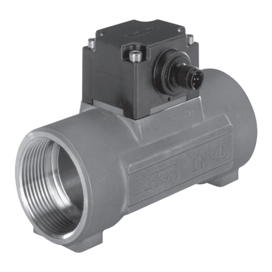
EINLEITUNG 1.3 BESTIMMUNGSGEMÄSSE VERWENDUNG Der Sensor 8011 ist zur Durchfluss-Messung von neutralen oder leicht aggressiven aber partikelfreien Flüssigkeiten bestimmt. Der Sensor 8011 ist nicht für die Durchflussmessung von Gasen geeignet. 1.4 AUFBAU UND MESSPRINZIP Der Sensor 8011 besteht aus einer mit integriertem Flügelrad SE11 Elektronik und einem S012 Fitting... -
Seite 5: Installation
Sensorelektronik auf das Fitting zurück danach ziehen Sie die 4 Schrauben mit einem Drehmoment von 1,5 Nm überkreuz an. Beachten Sie bitte die in dem folgenden Diagramm dargestellte Abhängigkeit zwischen Mediums-Druck und -Temperatur je nach Fittingwerkstoff: Flüssigkeit Metall (PN16) Flüssigkeit A : Anwendungsbereich von Fitting + Sensor 8011... - Seite 6 Verbesserung der Messgenauigkeit ein Strömungsgleichrichter verwendet werden. Einzelheiten entnehmen Sie den folgenden Abbildungen sowie der Norm EN ISO 5167-1. Mit einem Regelventil Rohrleitung mit 2 90°- Winkeln (dreidimensional) Rohrleitung mit Rohrleitung mit einer Biegung 2 90°-Winkeln oder mit einem T-Rohr Rohrerweiterung Rohrverengung 8011...
- Seite 7 Der Sensor 8011 gibt genaue Messungen, wenn folgende zusätzliche Bedingungen eingehalten werden: - Wenn der 8011 auf eine horizontale Rohrleitung montiert wird, muss das Flügelrad nach unten gerichtet sein. - das Rohr muss am Sensor zu jedem Zeitpunkt vollständig gefüllt sein.
-
Seite 8: Elektrischer Anschluss
- Wenn eine kombinierte Installation der Kabel unumgänglich ist, sollten ein mindestabstand von 30 cm eingehalten werden. - Verwenden Sie eine gefilterte und geregelte Stromversorgung. - Stellen Sie die Äquipotentialität der Installation sicher (Stromversorgung - 8011) : ♦ Die verschiedenen Erdungspunkte der Installation müssen aneinander angeschlossen sein, damit die zwischen zwei Erdungspunkten möglicherweise... -
Seite 9: Verkabelung Einer Ausführung Mit M12-Stecker
Ausführung mit 2 Ausführung mit einem (*) Funktionelle Erde Pulsausgängen, NPN und PNP NPN-Pulsausgang Anschluss des Pulsausgangs an eine SPS Je nach Ausführung des 8011 kann der Pulsausgang entweder in NPN- oder PNP-Modus angeschlossen werden. 8011 8011 NPN-Anschluss PNP-Anschluss (*) Funktionelle Erde 2.2.3 Verkabelung einer Ausführung mit Kabel... -
Seite 10: Technische Daten
300 cSt max. Feststoffanteil max. 1% Messbereich 0,3 m/s bis 10 m/s (je nach Fitting) ≤ ±0.5 % v. Endwert (10 m/s) Linearität Wiederholbarkeit 0.4% vom Messwert Messelement magnetischer Sensor ® ist eine Schutzmarke von Alfa Laval Inc. TriClamp 8011... -
Seite 11: Elektrische Daten
NPN- und PNP-Transistoren, open Kollektor, max. 700 mA, NPN-Ausgang: 0,2-36 VDC und PNP-Ausgang: Versorgungsspannung, Frequenz bis 300 Hz (Frequenz = K-Faktor x Durchfluss). 3.3 ELEKTRISCHER ANSCHLUSS Ausführung mit Kabel 1 m langes Kabel Ausführung mit Stecker verstellbarer M12-Stecker, 5 polig 8011... -
Seite 12: Material
Umgebungs- und Lager- Temperatur -15 °C bis +60 °C Relative Luftfeuchtigkeit < 80%, nicht kondensierend Schutzart des Gehäuses IP67 (Ausführung mit M12-Stecker) IP65 (Ausführung mit Kabel) 3.6 NORMENBEZÜGE Elektromagnetische Verträglichkeit: EN 61000-6-3 (2001) EN 61000-6-2 (2001) Vibration: EN 60068-2-6 Stoß: EN 60068-2-27 8011... -
Seite 13: K-Faktoren
Alle Fertigungen 29.2 PVDF Alle Fertigungen 73.2 52.5 29.5 10.3 K-Faktor in Impuls/US Gallone = K-Faktor in Impuls/l x 3,785 K-Faktor in Impuls/UK Gallone = K-Faktor in Impuls/l x 4,546 3.8 ABMESSUNGEN 3.8.1 Abmessungen des Elektronikmoduls SE11 Verseiltes Kabel 8011... -
Seite 14: Abmessungen Des 8011 Mit Innengewinde-Fitting G, Rc, Npt, Aus Edelstahl Oder Messing
TECHNISCHE DATEN 3.8.2 Abmessungen des 8011 mit Innengewinde-Fitting G, Rc, NPT, aus Edelstahl oder Messing [mm] [mm] [mm] [Inch] [mm] 57.5 84.0 16.0 NPT 1/2 17.0 15.0 55.0 94.0 17.0 NPT 3/4 18.3 16.3 55.2 104.0 23.5 NPT 1 18.0 18.0... -
Seite 15: Abmessungen Des 8011 Mit Außengewinde-Fitting Nach Sms 1145, Aus Edelstahl
TECHNISCHE DATEN 3.8.4 Abmessungen des 8011 mit Außengewinde-Fitting nach SMS 1145, aus Edelstahl [mm] [mm] [mm] 55.0 Rd40 x 1/6" 58.8 Rd60 x 1/6" 62.6 Rd70 x 1/6" 3.8.5 Abmessungen des 8011 mit Flansch-Fitting nach DIN 2633, ANSI B16-5-1988 und... -
Seite 16: Abmessungen Des 8011 Mit Schweißenden-Fitting Nach
TECHNISCHE DATEN 3.8.6 Abmessungen des 8011 mit Schweißenden-Fitting nach EN ISO 1127 / ISO 4200, SMS 3008 BS 4825/ASME BPE und DIN 11850 Reihe 2, aus Edelstahl Standard [mm] [mm] [mm] [mm] [mm] EN ISO 1127 / ISO 4200 SMS 3008 ASME BPE 52.5... -
Seite 17: Abmessungen Des 8011 Mit Triclamp
TECHNISCHE DATEN 3.8.7 Abmessungen des 8011 mit TriClamp ® -Fitting nach ISO (für Röhre nach EN ISO 1127 / ISO 4200), SMS 3017/ISO 2852 BS 4825 / ASME BPE und DIN 32676, aus Edelstahl Standard [mm] [mm] [mm] [mm] [mm] [mm] ISO (Röhre EN ISO 1127 / ISO 4200) -
Seite 18: Abmessungen Des 8011 Mit Klebe- Oder Schweißmuffen-Fitting Nach Din 8063, Astm D 1785/76 Und Jis K Aus Pvc, Din 16962 Aus Pp Oder Iso 10931 Aus Pvdf
TECHNISCHE DATEN 3.8.8 Abmessungen des 8011 mit Klebe- oder Schweißmuffen-Fitting nach DIN 8063, ASTM D 1785/76 und JIS K aus PVC, DIN 16962 aus PP oder ISO 10931 aus PVDF [mm] [mm] [mm] DIN/ISO ASTM DIN/ISO ASTM [mm] [mm] 29.5 34.5... -
Seite 19: Wartung
O-Ring für Metall-Fitting O-Ring für Kunststoff-Fitting Bevor Sie das Gerät demontieren: - Trennen Sie den 8011 von der Flüssigkeitszufuhr. - Vergewissern Sie sich, dass kein Druck oder Flüssigkeit mehr vorhanden sind. - Vergewissern Sie sich, dass kein Risiko entsteht, das Elektronikmodul vom Fitting abzubauen (Toxizität, Sauberkeits -oder... -
Seite 20: Information
INFORMATION 5.1 BESCHREIBUNG DER TYPENSCHILDER 5.1.1 Typenschild des 8011 Sensortyp Nominaler Durchfluss (DN) des Fittings: entweder DN6 oder DN8 (Angabe DN<15), oder DN15 bis 65 (Angabe DN >=15) Pulsausgangsdaten Rohranschluss Durchfluss-Messbereich CE-Logo Herstellernummer Werkstoffe des Fittings und der Dichtung in Kontakt mit der Flüssigkeit Seriennummer 10. -
Seite 21: Bestellnummern Des Elektronikmoduls Se11
M12-Stecker, 5 polig 4,5 (oder 6) - 36 VDC Puls, NPN + PNP 559445 DN15 bis DN65 4,5 - 24 VDC Puls, NPN 559446 1m-langes Kabel 4,5 (oder 6) - 36 VDC Puls, NPN + PNP 559447 Siehe Technische Daten 8011... -
Seite 22: Bestellnummern Der Ersatzteile Und Zubehör
EPDM - DN40 431565 EPDM - DN50 431566 Schraubensatz Bestellnummer 4 kurze Schrauben (M4x35 - A4) + 4 lange Schrauben (M4x60 - A4) 555775 Zubehör Bestellnummer 5-Pin M12-Gerätesteckdose, am Kabel angespritzt (2 m) 438680 5-Pin M12-Gerätesteckdose, zum kabeln 917116 8011... -
Seite 23: Anhang
* Für folgende Fittings: - mit Außengewinde nach SMS 1145 - Schweißenden nach SMS 3008, BS 4825 / ASME BPE oder DIN 11850 Reihe2 ® - TriClamp nach SMS 3017 / ISO 2852, BS 4825 / ASME BPE oder DIN 32676 8011... -
Seite 24: Eg-Konformitätserklärung
ANHANG EG-KONFORMITÄTSERKLÄRUNG 8011... -
Seite 48: Ec Declaration Of Conformity
ANNEX EC DECLARATION OF CONFORMITY 8011... -
Seite 72: Declaration De Conformite Ce
ANNEXES DECLARATION DE CONFORMITE CE 8011...